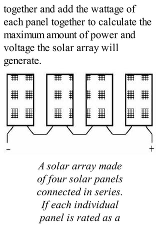
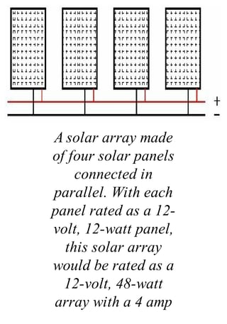
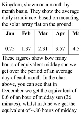
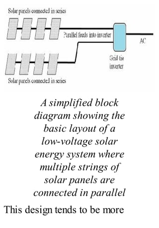
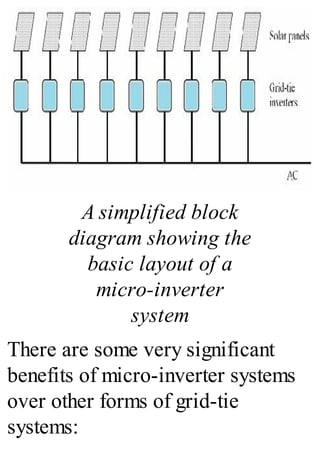
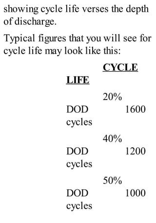
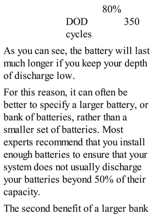
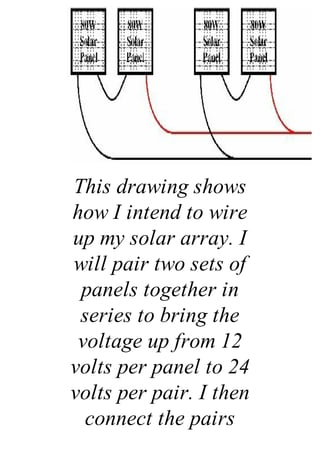
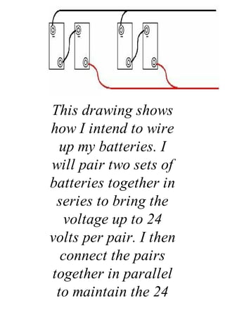
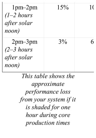
Solar Electricity Handbook
A simple, practical guide to solar
energy: how to design and install
photovoltaic solar electric systems
2012 Edition
Michael Boxwell
www.GreenstreamPublishing.com
Greenstream Publishing
12 Poplar Grove, Ryton on
Dunsmore, Warwickshire, CV8
3QE. United Kingdom
Copyright © Michael Boxwell
2009–2012
Published by Greenstream
Publishing 2012
Smashwords Edition: ISBN 978-1-
907670-23-7
Kindle Edition: ISBN 978-1-
907670-22-0
First Edition – published April
2009
Second Edition – published
November 2009
Third Edition – published March
2010
Fourth Edition – published January
2011
Fifth Edition – published October
2011
Sixth Edition – published February
2012
Editor: Sheila Glasbey
Michael Boxwell asserts the moral
right to be identified as the author
of this work.
A catalogue record for this book is
available from the British Library.
Whilst we have tried to ensure the
accuracy of the contents in this
book, the author or publishers
cannot be held responsible for any
errors or omissions found therein.
All rights reserved. No part of this
publication may be reproduced,
stored in a retrieval system, or
transmitted, in any form or by any
means, electronic, mechanical,
photocopying, recording or
otherwise, without the prior
permission of the publishers.
Table of Contents
Table of Contents
Introducing Solar Energy
Who this book is aimed at
The rapidly changing world of
solar energy
Solar electricity and solar heating
The source of solar power
The principles of solar electricity
Understanding the terminology
Setting expectations for solar
electricity
Why choose a solar electric
system?
Cost-justifying solar
Solar power and wind power
Fuel cells
Grid-tied solar electric systems
Solar electricity and the
environment
Environmental efficiency:
comparing supply and demand
In conclusion
A Brief Introduction to Electricity
Don’t panic
A brief introduction to electricity
How to measure electricity
The relationship between volts,
amps, ohms, watts and watt-hours
Volts
Power
Energy
A word for non-electricians
In conclusion
The Four Configurations for Solar
Power
Stand-alone/off-grid
Examples of simple stand-alone
systems
Grid-tie
An example of a grid-tie system
Grid-tie with power backup (grid
interactive)
An example of a grid interactive
system
Grid fallback
An example of a grid fallback
system
Grid failover
How grid-tie systems differ from
stand-alone
In conclusion
Components of a Solar Electric
System
Solar panels
Batteries
Controller
Inverter
Electrical devices
Connecting everything together
A stand-alone system
A grid-tie system using a single
central inverter
A grid-tie system using multiple
micro-inverters
In conclusion
The Design Process
Short-cutting the design work
Solar energy and emotions
In conclusion
Scoping the Project
Designing grid-tie or grid fallback
systems
Comparing supply with demand
Fleshing out the scope
Producing a power analysis
A word of warning
When you are ready to proceed
Calculating inefficiencies
Adding the inefficiencies to our
power analysis
When do you need to use the solar
system?
Keeping it simple
Improving the scope
In conclusion
Calculating Solar Energy
What is solar energy?
Why is this useful?
Calculating solar irradiance
Capturing more of the sun’s
energy
The impact of tilting solar
panels on solar irradiance
Calculating the optimum tilt for
solar panels
Getting the best from solar
panels at different times of the
year
Positioning your solar panels
Using solar irradiance to work
out how much energy a solar
panel will generate
Using solar irradiance to give
you an approximate guide for the
required power capacity of your
solar array
Solar panels and shade
Solar array power point
efficiencies
The effects of temperature on
solar panels
Temperature impact on solar
performance in Austin, Texas
during the summer months
Working out an approximate cost
What if the figures do not add
up?
Working out dimensions
In conclusion
Surveying Your Site
What we want to achieve
What you will need
First impressions
Drawing a rough sketch of the
site
Positioning the solar array
Roof-mounting
Ground-mounting
Pole-mounting
Splitting the solar array into
several smaller arrays
Identifying the path of the sun
across the sky
Shading
Professional tools for obstacle
analysis
Cell phone applications
Using paper and pencil
Future proof your system
What if there are shading
obstructions?
Positioning batteries, controllers
and inverters
Cabling
Site survey for the holiday home
In conclusion
Understanding the Components
How to use these chapters
Common components for all
systems
Solar panels
Amorphous solar panels
Polycrystalline solar panels
Monocrystalline solar panels
Which solar panel technology is
best?
What to look for when choosing
a solar panel
Buying cheap solar panels
Second-hand solar PV panels
Fresnel lenses and mirrors
Solar panel mountings
Solar trackers
Solar array cables
Fuses and isolation switches
Ground fault protection
Components for Grid-Tie systems
High voltage in-series
Low voltage systems
Micro-inverter systems
Grid-tie solar panels
Grid-tie inverters
Input voltage
Power rating
Power tracking
Multiple strings
Diagnostics and reporting
information
Built-in safety
Installation options and
operating environment
Buying from eBay
Components for Stand-Alone
Systems
Calculate your optimum voltage
Voltages and currents
What voltages can I run at?
How to work out what voltage
you should be running at
How to calculate your current
Calculating cable thicknesses
Converting wire sizes:
Mixing and matching solar panels
Batteries
Types of batteries
Battery configurations
Battery lifespan
Holdover
Calculating how long a set of
batteries will last
Second-hand batteries
Building your battery bank
Battery safety
Solar controller
Balancing the batteries
Allow for expansion
Maximum power point tracking
Ground fault protection
Backup power
Using multiple controllers
Inverters
Battery bank voltage
Power rating
Waveform
Installation options and
operating environment
Ground fault protection
Cables
Battery cables
Appliance cabling
Plugs and sockets
Appliances
Lighting
Refrigeration
Microwave ovens
Televisions, DVDs, computer
games consoles and music
Music systems
Dishwashers, washing machines
and tumble dryers
Air conditioning systems
Reputable brand names
Solar panel manufacturers and
brands
Solar controller and inverter
manufacturers and brands
Battery manufacturers and
brands
Shopping list for the holiday home
In conclusion
Planning, regulations and approvals
National and international
standards for solar components
Installation regulations
Getting your electricity supplier
involved
Solar grants and selling your
power
General information about
grants, tax credits and feed-in
tariffs
In conclusion
Detailed Design
Safety is designed in
What is the worst that can
happen with a solar installation?
Grounding your electrics
DC Electrics
AC electrics
High temperatures
Think safety
Solar array design
Solar array design – stand-alone
systems
Solar array design – grid-tie
systems with micro-inverters
Solar array design – grid-tie
systems with a single inverter
Batteries
Controller
Inverter
Devices
Specifics for a grid fallback
system
Circuit protection
Earthing (grounding)
DC circuit protection
AC circuit protection
Cable sizing and selection
Sizing your cables
Protecting cable runs
Designing your system to keep
your cables runs as short as
possible
Selecting solar cable
Controller cable
Battery interconnection cables
Some sample wiring diagrams
The holiday home wiring
diagram
The next step
Solar frame mounting
Positioning batteries
Planning the installation
In conclusion
Installation
Have you read the instructions?
Safety
Your First Aid kit
Chemical clean-up kit
Considering the general public
Working at height
Handling
Working with batteries
Gloves
Electrical safety
Assembling your toolkit
Preparing your site
Testing your solar panels
Installing the solar array
Cleaning the panels
Assembly and connections
Roof-mounting a solar array
Final wiring
Installing the batteries
Pre-installation
Positioning the batteries
Ventilation
Access
Insulation
Connections
Installing the control equipment
Installing a grid-tie system
Commissioning the system
Programming your solar
controller
Testing your system
Charging up your batteries
Connecting your devices
In conclusion
Troubleshooting
Keep safe
Common faults
Excessive power usage
Solutions
Insufficient power generation
Solutions
Damaged wiring/ poor
connections
Weak battery
Changing batteries
Inverter issues
Maintaining Your System
As required
Every month
Every three months
Every six months
Every year
At the start of each winter
Internet Support
Tools available on the website
Online project analysis
Monthly insolation figures
Solar angle calculator
Solar resources
Questions and answers
Author online!
Solar articles
A Final Word
Appendix A – Crystalline Solar
Panels and Shading
Types of obstruction
Designing shade-tolerant solar
systems
Track the shade
Increasing the number of solar
panels
Panel orientation
Choice of solar panel
Use micro-inverters
Design a parallel solar array
Design a multi-string solar array
Other options
If all else fails...
In conclusion
Appendix B – Solar Insolation
Understanding this information
Solar insolation values –
Australia
Solar insolation values –
Canada
Solar insolation values – Ireland
Solar insolation values – New
Zealand
Solar insolation values – United
Kingdom
Solar insolation values – United
States of America
Appendix C – Typical Power
Requirements
Household and office
Garden and DIY
Caravans, boats and recreational
vehicles
Appendix D – Living Off-Grid
A solar electric system in
conjunction with grid electricity
Appendix E – Other Solar Projects
Grid fallback system/ grid
failover system
Portable solar power unit
Solar boat
Solar shed light
Solar electric bikes
Appendix F – Building Your Own
Solar Panels (and Why You
Shouldn’t)
Introducing Solar
Energy
Ninety-three million miles from
Earth, our sun is 333,000 times the
size of our planet. It has a diameter
of 865,000 miles, a surface
temperature of 5,600°C and a core
temperature of 15,000,000°C. It is a
huge mass of constant nuclear
activity.
Directly or indirectly, our sun
provides all the power we need to
exist and supports all life forms.
The sun drives our climate and our
weather. Without it, our world
would be a frozen wasteland of ice-
covered rock.
Solar electricity is a wonderful
concept. Taking power from the sun
and using it to power electrical
equipment is a terrific idea. There
are no ongoing electricity bills, no
reliance on a power socket: a free
and everlasting source of energy
that does not harm the planet!
Of course, the reality is a little
different from that. Yet generating
electricity from sunlight alone is a
powerful resource, with
applications and benefits throughout
the world.
But how does it work? For what is
it suitable? What are the
limitations? How much does it
cost? How do you install it? This
book answers all these questions
and shows you how to use the
power of the sun to generate
electricity yourself.
Along the way, I will also expose a
few myths about some of the wilder
claims made about solar energy and
I will show you where solar power
may only be part of the solution.
Although undoubtedly there are
some significant environmental
benefits of solar electricity, I will
also be talking about where its
environmental credentials have
been oversold.
I will keep the descriptions as
straightforward as possible. There
is some mathematics and science
involved. This is essential to allow
you to plan a solar electric
installation successfully. However,
none of it is complicated and there
are plenty of short-cuts to keep
things simple.
The book includes a number of
example projects to show how you
can use solar electricity. Some of
these are very straightforward, such
as providing electrical light for a
shed or garage, for example, or
fitting a solar panel to the roof of a
caravan or boat. Others are more
complicated, such as installing
photovoltaic solar panels to a
house.
I also show some rather more
unusual examples, such as the
possibilities for solar electric
motorbikes and cars. These are
examples of what can be achieved
using solar power alone, along with
a little ingenuity and determination.
I have used one main example
throughout the book: providing
solar-generated electricity for a
holiday home which does not have
access to an electricity supply from
the grid. I have created this example
to show the issues and pitfalls that
you may encounter along the way,
based on real life issues and
practical experience.
A website accompanies this book.
It has lots of useful information,
along with lists of suppliers and a
suite of online solar energy
calculators that will simplify the
cost analysis and design processes.
The website is at
www.SolarElectricityHandbook.com
Who this book is aimed
at
If you simply want to gain an
understanding about how solar
electricity works then this handbook
will provide you with everything
you need to know.
If you are planning to install your
own stand-alone solar power
system, this handbook is a
comprehensive source of
information that will help you
understand solar and guide you in
the design and installation of your
own solar electric system.
Solar has a big application for
integrating into electrical products:
mobile phones, laptop computers,
portable radios. Even light electric
cars can use solar energy to provide
some or all of their power
requirements, depending on the
application. If you are a designer,
looking to see how you can
integrate solar into your product,
this book will give you a grounding
in the technology that you will need
to get you started.
If you are specifically looking to
install a grid-tie system, i.e. a solar
energy system that will feed
electricity back into your local
power grid, this book will provide
you with a good foundation and will
allow you to carry out the design of
your system. You will still need to
check the local planning laws and
any other local legislation
surrounding the installation of solar
energy systems, and you will have
to understand the building of
electrical systems. In some
countries, you specifically need to
be certified in order to carry out the
physical installation of a grid-tie
system.
If you are planning to install larger,
commercial–size systems, or if you
are hoping to install grid-tie solar
systems professionally, then this
book will serve as a good
introduction, but you will need to
grow your knowledge further. This
book gives you the foundations you
need in order to build this
knowledge, but there are special
skills required when designing and
implementing larger scale solar
systems that go far beyond what is
required for smaller systems and
are beyond the scope of this book.
If you are planning your own solar
installation, it will help if you have
some DIY skills. Whilst I include a
chapter that explains the basics of
electricity, a familiarity with wiring
is also of benefit for smaller
projects and you will require a
thorough understanding of electrical
systems if you are planning a larger
project such as powering a house
with solar.
The rapidly changing
world of solar energy
I wrote the first edition of this book
early in 2009. It is not a long time
ago. Yet this 2012 issue is the sixth
edition. In every edition, I have had
to rewrite significant sections of the
book and significantly update the
website in order to keep up with the
rapid pace of change.
The rapid improvement in the
technology and the freefall in costs
since early 2009 have transformed
the industry. Systems that were
completely unaffordable or
impractical just two or three years
ago are now cost-effective and
achievable.
Solar panels available today are
smaller, more robust and better
value for money than ever before.
For many more applications, solar
is now the most cost-effective way
to generate electricity.
Over the coming years, all the signs
are that the technology and the
industry will continue to evolve at a
similar pace. By 2015, solar will
be the cheapest form of electricity
generator, undercutting traditionally
low-cost electricity generators such
as coal-fired power stations. We
are likely to see solar energy
incorporated into more everyday
objects such as laptop computers,
mobile phones, backpacks and
clothing. Meanwhile, solar energy
is causing a revolution for large
areas of Asia and Africa, where
entire communities are now gaining
access to electricity for the first
time.
As an easy-to-use and low-carbon
energy generator, solar is without
equal. Its potential for changing the
way we think about energy in the
future is huge. For families and
businesses in rural African and
Asian villages, it is creating a
revolution.
Solar electricity and solar
heating
Solar electricity is produced from
sunlight shining on photovoltaic
solar panels. This is different to
solar hot water or solar heating
systems, where the power of the sun
is used to heat water or air.
Solar heating systems are beyond
the remit of this book. That said,
there is some useful information on
surveying and positioning your
solar panels later on that is relevant
to both solar photovoltaics and
solar heating systems.
If you are planning to use solar
power to generate heat, solar
heating systems are far more
efficient than solar electricity,
requiring far smaller panels to
generate the same amount of energy.
Solar electricity is often referred to
as photovoltaic solar, or PV solar.
This describes the way that
electricity is generated in a solar
panel.
For the purposes of this book,
whenever I refer to solar panels I
am talking about photovoltaic solar
panels for generating electricity,
and not solar heating systems.
The source of solar
power
Deep in the centre of the sun,
intense nuclear activity generates
huge amounts of radiation. In turn,
this radiation generates light energy
called photons. These photons have
no physical mass of their own, but
carry huge amounts of energy and
momentum.
Different photons carry different
wavelengths of light. Some photons
will carry non-visible light (infra-
red and ultra-violet), whilst others
will carry visible light (white
light).
Over time, these photons push out
from the centre of the sun. It can
take one million years for a photon
to push out to the surface from the
core. Once they reach the sun’s
surface, these photons rush through
space at a speed of 670 million
miles per hour. They reach earth in
around eight minutes.
On their journey from the sun to
earth, photons can collide with and
be deflected by other particles, and
are destroyed on contact with
anything that can absorb radiation,
generating heat. That is why you
feel warm on a sunny day: your
body is absorbing photons from the
sun.
Our atmosphere absorbs many of
these photons before they reach the
surface of the earth. That is one of
the two reasons that the sun feels so
much hotter in the middle of the
day. The sun is overhead and the
photons have to travel through a
thinner layer of atmosphere to reach
us, compared to the end of the day
when the sun is setting and the
photons have to travel through a
much thicker layer of atmosphere.
This is also one of the two reasons
why a sunny day in winter is so
much colder than a sunny day in
summer. In winter, when your
location on the earth is tilted away
from the sun, the photons have to
travel through a much thicker layer
of atmosphere to reach us.
(The other reason that the sun is
hotter during the middle of the day
than at the end is because the
intensity of photons is much higher
at midday. When the sun is low in
the sky, these photons are spread
over a greater distance simply by
the angle of your location on earth
relative to the sun.)
The principles of solar
electricity
A solar panel generates electricity
using the photovoltaic effect, a
phenomenon discovered in the early
19th century when scientists
observed that certain materials
produced an electric current when
exposed to light.
Two layers of a semi-conducting
material are combined to create this
effect. One layer has to have a
depleted number of electrons. When
exposed to sunlight, the layers of
material absorb the photons. This
excites the electrons, causing some
of them to ‘jump’ from one layer to
the other, generating an electrical
charge.
The semi-conducting material used
to build a solar cell is silicon, cut
into very thin wafers. Some of these
wafers are then ‘doped’ to
contaminate them, thereby creating
an electron imbalance in the wafers.
The wafers are then aligned
together to make a solar cell.
Conductive metal strips attached to
the cells take the electrical current.
When a photon hit the solar cell, it
can do one of three things: it can be
absorbed by the cell, reflected off
the cell or pass straight through the
cell.
It is when a photon is absorbed by
the silicon that an electrical current
is generated. The more photons (i.e.
the greater intensity of light) that are
absorbed by the solar cell, the
greater the current generated.
Solar cells generate most of their
electricity from direct sunlight.
However, they also generate
electricity on cloudy days and some
systems can even generate very
small amounts of electricity on
bright moonlit nights.
Individual solar cells typically only
generate tiny amounts of electrical
energy. To make useful amounts of
electricity, these cells are
connected together to make a solar
module, otherwise known as a solar
panel or, to be more precise, a
photovoltaic module.
Understanding the
terminology
In this book, I use various terms
such as ‘solar electricity’, ‘solar
energy’ and ‘solar power’. Here is
what I mean when I am talking
about these terms:
Solar power is a general term for
generating power, whether heat or
electricity, from the power of the
sun.
Solar energy refers to the energy
generated from solar power,
whether electrical or as heat.
Solar electricity refers to
generating electrical power using
photovoltaic solar panels.
Solar heating refers to generating
hot water or warm air using solar
heating panels or ground-source
heat pumps.
Setting expectations for
solar electricity
Solar power is a useful way of
generating modest amounts of
electricity, so long as there is a
good amount of sunlight available
and your location is free from
obstacles such as trees and other
buildings that will shade the solar
panel from the sun.
Solar experts will tell you that solar
electricity is normally only
cost-effective where there is no
other source of electricity
available.
Whilst this is often the case, there
are plenty of exceptions to this rule.
Often solar electricity can be
extremely practical and can save
you money over the more traditional
alternatives. Some examples might
include:
· Installing a light or a power
source somewhere where it is
tricky to get a standard
electricity supply, such as in
the garden, shed or remote
garage
· Creating a reliable and
continuous power source
where the standard electricity
supply is unreliable because
of regular power cuts
· Building a mobile power
source that you can take with
you, such as a power source
for use whilst camping,
working on outdoor DIY
projects or working on a
building site
· Creating green energy for
your own use and selling
surplus energy production
back to the electricity
suppliers through a feed-in
tariff
The amount of energy you need to
generate has a direct bearing on the
size and cost of a solar electric
system. The more electricity you
need, the more difficult and more
expensive your system will
become.
If your requirements for solar
electricity are to run a few lights, to
run some relatively low-power
electrical equipment such as a
laptop computer, a small TV, a
compact fridge and a few other
small bits and pieces, then if you
have a suitable location you can
achieve what you want with solar.
On the other hand, if you want to
run high-power equipment such as
fan heaters, washing machines and
power tools, you are likely to find
that the costs will rapidly get out of
control.
As I mentioned earlier, solar
electricity is not well suited to
generating heat: heating rooms,
cooking and heating water all take
up significant amounts of energy.
Using electricity to generate this
heat is extremely inefficient. Instead
of using solar electricity to generate
heat, you should consider a solar
hot water heating system, and
heating and cooking with gas or
solid fuels.
It is possible to power the average
family home purely on solar
electricity without making any cuts
in your current electricity
consumption. However, it is not
cheap, and you will need a lot of
roof space to fit all the panels! It is
usually a good idea to carefully
evaluate your electricity usage and
make savings where you can before
you proceed.
Most households and businesses are
very inefficient with their electrical
usage. Spending some time first
identifying where electricity is
wasted and eliminating this waste is
an absolute necessity if you want to
implement solar electricity
cost-effectively.
This is especially true if you live in
cooler climates, such as Northern
Europe or Canada, where the
winter months produce much lower
levels of solar energy. In the United
Kingdom, for instance, the roof of
the average-sized home is not large
enough to hold all the solar panels
that would be required to provide
the electricity used by the average
household throughout the year. In
this instance, making energy savings
is essential.
For other applications, a solar
electric installation is much more
cost-effective. For instance, no
matter which country you live in,
providing electricity for a holiday
home is well within the capabilities
of a solar electric system, so long
as heating and cooking are catered
for using gas or solid fuels and the
site is in a sunny position with little
or no shade. In this scenario, a solar
electric system may be more
cost-effective than installing a
conventional electricity supply if
the house is off-grid and is not
close to a grid electricity
connection.
If your requirements are more
modest, such as providing light for
a lock-up garage, for example, there
are off-the-shelf packages to do this
for a very reasonable cost. Around
£70–£100 ($110–$160) will
provide you with a lighting system
for a shed or small garage, whilst
£200 ($300) will provide you with
a system big enough for lighting
large stables or a workshop.
This is far cheaper than installing a
conventional electricity supply into
a building, which can be expensive
even when a local supply is
available just outside the door.
Low-cost solar panels are also
ideal for charging up batteries in
caravans and recreational vehicles
or on boats, ensuring that the
batteries get a trickle charge
between trips and keeping the
batteries in tip-top condition whilst
the caravan or boat is not in use.
Why choose a solar
electric system?
There are a number of reasons to
consider installing a solar electric
system:
· Where there is no other
source of electrical power
available, or where the cost
of installing conventional
electrical power is too high
· Where other sources of
electrical power are not
reliable. For example, when
power cuts are an issue and a
solar system can act as a
cost-effective contingency
· When a solar electric
system is the most convenient
and safest option. For
example, installing low
voltage solar lighting in a
garden or providing courtesy
lighting in a remote location
· You can become entirely
self sufficient with your own
electrical power
· Once installed, solar power
provides virtually free power
without damaging the
environment
Cost-justifying solar
Calculating the true cost of
installing a solar electric system
depends on various factors:
· The power of the sun at
your location at different
times of the year
· How much energy you need
to generate
· How good your site is for
capturing sunlight
Compared to other power sources,
solar electric systems typically
have a comparatively high capital
cost, but a low ongoing maintenance
cost.
To create a comparison with
alternative power sources, you will
often need to calculate a payback of
costs over a period of a few years
in order to justify the initial cost of
a solar electric system.
On all but the simplest of
installations, you will need to carry
out a survey on your site and carry
out some of the design work before
you can ascertain the total cost of
installing a photovoltaic system. Do
not panic: this is not as frightening
as it sounds. It is not difficult and I
cover it in detail in later chapters.
We can then use this figure to put
together a cost-justification on your
project to compare with the
alternatives.
Solar power and wind
power
Wind turbines can be a good
alternative to solar power, but
probably achieve their best when
implemented together with a solar
system: a small wind turbine can
generate electricity in a breeze even
when the sun is not shining.
Small wind turbines do have some
disadvantages. Firstly, they are very
site-specific, requiring higher than
average wind speeds and minimal
turbulence. They must be higher
than surrounding buildings and
away from tall trees. If you live on
a windswept farm or close to the
coast, a wind turbine can work
well. If you live in a built-up area
or close to trees or main roads, you
will find a wind turbine unsuitable
for your needs.
Compared to the large wind
turbines used by the power
companies, small wind turbines are
not particularly efficient. If you are
planning to install a small wind
turbine in combination with a solar
electric system, a smaller wind
turbine that generates a few watts of
power at lower wind speeds is
usually better than a large wind
turbine that generates lots of power
at high wind speeds.
Fuel cells
Fuel cells can be a good way to
supplement solar energy, especially
for solar electric projects that
require additional power in the
winter months, when solar energy is
at a premium.
A fuel cell works like a generator.
It uses a fuel mixture such as
methanol, hydrogen or zinc to create
electricity.
Unlike a generator, a fuel cell
creates energy through chemical
reactions rather than through
burning fuel in a mechanical engine.
These chemical reactions are far
more carbon-efficient than a
generator.
Fuel cells are extremely quiet,
although rarely completely silent,
and produce water as their only
emission. This makes them suitable
for indoor use with little or no
ventilation.
Grid-tied solar electric
systems
Grid-tied solar electric systems
connect directly into the electricity
grid. When the sun is shining during
the day, excess electricity feeds into
the grid. During the evening and
night, when the solar panels are not
providing sufficient power,
electricity is taken from the grid as
required.
Grid-tied solar electric systems
effectively create a micro power
station. Electricity can be used by
other people as well as yourself. In
some countries, owners of grid-tied
solar electric systems receive
payment for each kilowatt of power
they sell to the electricity
providers.
Because a grid-tied solar electric
system becomes part of the utility
grid, the system will switch off in
the event of a power cut. It does this
to stop any current flowing back
into the grid, which could be fatal
for engineers repairing a fault.
Solar electricity and the
environment
Once installed, a solar electric
system is a low-carbon electricity
generator: the sunlight is free and
the system maintenance is extremely
low.
There is a carbon footprint
associated with the manufacture of
solar panels, and in the past this
footprint has been quite high,
mainly due to the relatively small
volumes of panels being
manufactured and the chemicals
required for the ‘doping’ of the
silicon in the panels.
Thanks to improved manufacturing
techniques and higher volumes, the
carbon footprint of solar panels is
now much lower. You can typically
offset the carbon footprint of
building the solar panels by the
energy generated within 2–5 years,
and some of the very latest
amorphous thin-film solar panels
can recoup their carbon footprint in
as little as six months.
Therefore, a solar electric system
that runs as a complete stand-alone
system can reduce your carbon
footprint, compared to taking the
same power from the grid.
Grid-tied solar systems are slightly
different in their environmental
benefit, and their environmental
payback varies quite dramatically
from region to region, depending on
a number of factors:
· How grid electricity is
generated by the power
companies in your area (coal,
gas, nuclear, hydro, wind or
solar)
· Whether or not your
electricity generation
coincides with the peak
electricity demand in your
area (such as air conditioning
usage in hot climates, or high
electrical usage by nearby
heavy industry)
It is therefore much more difficult to
put an accurate environmental
payback figure on grid-tied solar
systems.
It is undeniably true that some
people who have grid-tied solar
power actually make no difference
to the carbon footprint of their
home. In colder climates, the
majority of electricity consumption
is in the evenings and during the
winter. If you have grid-tie solar
but sell most of your energy to the
utility companies during the day in
the summer and then buy it back to
consume in the evenings and in the
winter, you are making little or no
difference to the overall carbon
footprint of your home. In effect,
you are selling your electricity
when there is a surplus and buying
it back when there is high demand
and all the power stations are
working at full load.
In warmer climates, solar energy
can make a difference. In a hot area,
peak energy consumption tends to
occur on sunny days as people try to
keep cool with air conditioning. In
this scenario, peak electricity
demand occurs at the same time as
peak energy production from a solar
array, and a grid-tie solar system
can be a perfect fit.
If you live in a colder climate, this
does not mean that there is no point
in installing a grid-tie solar system.
It does mean that you need to take a
good hard look at how and when
you consume electricity. Do not just
assume that because you can have
solar panels on the roof of your
house, you are automatically
helping the environment.
From an environmental perspective,
if you wish to get the very best out
of a grid-tie system, you should try
to achieve the following:
· Use the power you generate
for yourself
· Use solar energy for high
load applications such as
clothes washing
· Reduce your own power
consumption from the grid
during times of peak demand
Environmental efficiency:
comparing supply and
demand
There is an online calculator that
will allow you to map your
electricity usage over a period of a
year and compare it with the amount
of sunlight available to your home.
Designed specifically for grid-tie
installations, this calculator allows
you to see how close a fit solar
energy is in terms of supply and
demand.
Whilst this online calculator is no
substitute for a detailed electrical
usage survey and research into the
exact source of the electricity
supplied to you at your location, it
will give you a good indication of
the likely environmental
performance of a solar energy
system.
To use this online calculator, you
will need to collate information
about your electricity usage for
each month of the year. You will
usually find this information on your
electricity bill or by contacting your
electricity provider. Then visit
www.SolarElectricityHandbook.com
follow the links to the Grid-Tie
Solar Calculator in the Online
Calculators section and fill in the
online questionnaire.
In conclusion
· Solar electricity can be a
great source of power where
your power requirements are
modest, there is no other
source of electricity easily
available and you have a
good amount of sunshine
· Solar electricity is not the
same as solar heating
· Solar panels absorb photons
from sunlight to generate
electricity
· Direct sunlight generates the
most electricity. Dull days
still generate some power
· Solar electricity is unlikely
to generate enough electricity
to power the average family
home, unless major
economies in the household
power requirements are made
first
· Larger solar electric
systems have a comparatively
high capital cost, but the
ongoing maintenance costs
are very low
· Smaller solar electric
system can actually be
extremely cost-effective to
buy and install, even when
compared to a conventional
electricity supply
· It can be much cheaper
using solar electricity at a
remote building, rather than
connecting it to a
conventional grid electricity
supply
· Stand-alone solar energy
systems can have a big
environmental benefit if they
negate the need for a
connection to grid power
· Grid-tie solar energy
systems have an
environmental benefit in
sunny climates where typical
electricity usage patterns are
similar to the supply of
sunlight
· In colder regions, where
electricity usage is highest
when sunlight is in short
supply, the environmental
benefits are less certain
A Brief Introduction
to Electricity
Before we can start playing with
solar power, we need to talk about
electricity. To be more precise, we
need to talk about voltage, current,
resistance, power and energy.
Having these terms clear in your
head will help you to understand
your solar system. It will also give
you confidence that you are doing
the right thing when it comes to
designing and installing your
system.
Don’t panic
If you have not looked at electrics
since you were learning physics at
school, some of the principles of
electricity can be a bit daunting to
start with. Do not worry if you do
not fully grasp everything on your
first read through.
There are a few calculations that
I show on the next few pages, but I
am not expecting you to remember
them all! Whenever I use these
calculations later on in the book, I
show all my workings and, of
course, you can refer back to this
chapter as you gain more
knowledge on solar energy.
Furthermore, the website that
accompanies this book includes a
number of online tools that you can
use to work through most of the
calculations involved in designing a
solar electric system. You will not
be spending hours with a slide-rule
and reams of paper working all this
out by yourself.
A brief introduction to
electricity
When you think of electricity, what
do you think of? Do you think of a
battery that is storing electricity?
Do you think of giant overhead
pylons transporting electricity? Do
you think of power stations that are
generating electricity? Or do you
think of a device like a kettle or
television set or electric motor that
is consuming electricity?
The word electricity actually
covers a number of different
physical effects, all of which are
related but distinct from each other.
These effects are electric charge,
electric current, electric potential
and electromagnetism:
· An electric charge is a
build-up of electrical energy.
It is measured in coulombs. In
nature, you can witness an
electric charge in static
electricity or in a lightning
strike. A battery stores an
electric charge
· An electric current is the
flow of an electric charge,
such as the flow of electricity
through a cable. It is
measured in amps
· An electric potential refers
to the potential difference in
electrical energy between
two points, such as between
the positive tip and the
negative tip of a battery. It is
measured in volts. The
greater the electric potential
(volts), the greater capacity
for work the electricity has
· Electromagnetism is the
relationship between
electricity and magnetism,
which enables electrical
energy to be generated from
mechanical energy (such as in
a generator) and enables
mechanical energy to be
generated from electrical
energy (such as in an electric
motor)
How to measure
electricity
Voltage refers to the potential
difference between two points. A
good example of this is an AA
battery: the voltage is the difference
between the positive tip and the
negative end of the battery. Voltage
is measured in volts and has the
symbol ‘V’.
Current is the flow of electrons in a
circuit. Current is measured in
amps (A) and has the symbol ‘I’. If
you check a power supply, it will
typically show the current on the
supply itself.
Resistance is the opposition to an
electrical current in the material the
current is flowing through.
Resistance is measured in ohms and
has the symbol ‘R’.
Power measures the rate of energy
conversion. It is measured in watts
(W) and has the symbol ‘P’. You
will see watts advertised when
buying a kettle or vacuum cleaner:
the higher the wattage, the more
power the device consumes and the
faster (hopefully) it does its job.
Energy refers to the capacity for
work: power multiplied by time.
Energy has the symbol ‘E’. Energy
is usually measured in joules (a
joule equals one watt-second), but
electrical energy is usually shown
as watt-hours (Wh), or kilowatt-
hours (kWh), where 1 kWh = 1,000
Wh.
The relationship between
volts, amps, ohms, watts
and watt-hours
Volts
Current x Resistance = Volts
I x R = V
Voltage is equal to current
multiplied by resistance. This
calculation is known as Ohm’s
Law. As with power calculations,
you can express this calculation in
different ways. If you know volts
and current, you can calculate
resistance. If you know volts and
resistance, you can calculate
current:
Volts ÷ Resistance = Current
V ÷ R = I
Volts ÷ Current = Resistance
V ÷ I = R
Power
Volts x Current = Power
V x I = P
Power is measured in watts. It
equals volts times current. A 12-
volt circuit with a 4-amp current
equals 48 watts of power (12 x 4 =
48).
Based on this calculation, we can
also work out voltage if we know
power and current, and current if
we know voltage and power:
Power ÷ Current = Volts
P ÷ I = V
Example: A 48-watt motor with a
4-amp current is running at 12 volts.
48 watts ÷ 4 amps = 12 volts
Current = Power ÷ Volts
I = P ÷ V
Example: a 48-watt motor with a
12-volt supply requires a 4-amp
current.
48 watts ÷ 12 volts = 4 amps
Power (watts) is also equal to the
square of the current multiplied by
the resistance:
Current² x Resistance = Power
I² x R = P
Energy
Energy is a measurement of power
over a period of time. It shows how
much power is used, or generated,
by a device, typically over a period
of an hour. In electrical systems, it
is measured in watt-hours (Wh) and
kilowatt-hours (kWh).
A device that uses 50 watts of
power, has an energy demand of
50Wh per hour. A solar panel that
can generate 50 watts of power per
hour, has an energy creation
potential of 50Wh per hour.
However, because solar energy
generation is so variable, based on
temperature, weather conditions,
the time of day and so on, a new
figure is now often shown
specifically for solar systems: a
watt-peak (Wp) rating.
A watt-peak rating shows how
much power can be generated by a
solar panel at its peak rating. It has
been introduced to highlight the fact
that the amount of energy a solar
panel can generate is variable and
to remind consumers that a solar
panel rated at 50 watts is not going
to be producing 50 watt-hours of
energy every single hour of every
single day.
A word for non-
electricians
Realistically, if you are new to
electrical systems, you should not
be planning to install a big solar
energy system yourself. If you want
a low-voltage system to mount to
the roof of a boat, garden shed or
barn, or if you want to play with the
technology and have some fun, then
great: this book will tell you
everything you need to know.
However, if the limit of your
electrical knowledge is wiring a
plug or replacing a fuse, you should
not be thinking of physically wiring
and installing a solar energy system
yourself without learning more
about electrical systems and
electrical safety first.
Furthermore, if you are planning to
install a solar energy system to the
roof of a house, be aware that in
many parts of the world you need to
have electrical qualifications in
order to carry out even simple
household wiring.
That does not mean that you cannot
specify a solar energy system,
calculate the size you need and buy
the necessary hardware for a big
project. It does mean that you are
going to need to employ a specialist
to check your design and carry out
the installation.
In conclusion
· Understanding the basic
rules of electricity makes it
much easier to put together a
solar electric system
· As with many things in life,
a bit of theory makes a lot
more sense when you start
applying it in practice
· If this is your first
introduction to electricity,
you may find it useful to run
through it a couple of times
· You may also find it useful
to bookmark this section and
refer back to it as you read on
· You will also find that,
once you have learned a bit
more about solar electric
systems, some of the terms
and calculations will start to
make a bit more sense.
· If you are not an electrician,
be realistic in what you can
achieve. Electrics can be
dangerous and you do not
want to get it wrong. You can
do most of the design work
yourself, but you are going to
need to get a specialist in to
check your design and carry
out the installation.
The Four
Configurations for
Solar Power
There are four different
configurations you can choose from
when creating a solar electricity
installation. These are stand-alone
(sometimes referred to as off-grid),
grid-tie, grid-tie with power backup
(also known as grid interactive)
and grid fallback.
Here is a brief introduction to these
different configurations:
Stand-alone/off-grid
Worldwide, stand-alone solar
photovoltaic installations are the
most popular type of solar
installation there is. It is what solar
photovoltaics were originally
created for: to provide power at a
location where there is no other
source easily available.
Whether it is powering a shed light,
providing power for a pocket
calculator or powering a complete
off-grid home, stand-alone systems
fundamentally all work in the same
way: the solar panel generates
power, the energy is stored in a
battery and then used as required.
In general, stand-alone systems are
comparatively small systems,
typically with a peak power
generation of under one kilowatt.
Almost everyone can benefit from a
stand-alone solar system for
something, even if it is something as
mundane as providing an outside
light somewhere. Even if you are
planning on something much bigger
and grander, it is often a good idea
to start with a very small and
simple stand-alone system first.
Learn the basics and then progress
from there.
Examples of simple stand-
alone systems
The vending machine
ByBox is a manufacturer of
electronic lockers. These are
typically used for left luggage at
railway stations or at airports, or
situated at shopping malls or fuel
stations and used as part of a
delivery service for people to
collect internet deliveries, so they
do not need to wait at home.
One of the biggest issues with
electronic lockers has often been
finding suitable locations to place
them where a power source is
available. ByBox overcame this
issue by building an electronic
locker with a solar roof to provide
permanent power to the locker.
The solar roof provides power to a
set of batteries inside the locker.
When not in use, the locker itself is
in standby mode, thereby consuming
minimal power. When a customer
wishes to use the locker, they press
the START button and use the
locker as normal.
The benefit to ByBox has been
twofold: they can install a locker
bank in any location, without any
dependence on a power supply.
Secondly, the cost of the solar
panels and controllers is often less
than the cost of installing a separate
electricity supply, even if there is
one nearby.
Recreational vehicles
Holidaying with recreational
vehicles or caravans is on the
increase, and solar energy is
changing the way people are going
on holiday.
In the past, most RV owners elected
to stay on larger sites, which
provided access to electricity and
other facilities. As recreational
vehicles themselves become more
luxurious, however, people are now
choosing to travel to more remote
locations and live entirely ‘off-
grid’, using solar energy to provide
electricity wherever they happen to
be. Solar is being used to provide
all the comforts of home, whilst
offering holidaymakers the freedom
to stay wherever they want.
Grid-tie
Grid-tie is gaining popularity in
Europe and the United States. This
is due to the availability of grants to
reduce the installation costs and the
ability to earn money by selling
electricity back into the electricity
companies through a feed-in tariff.
Feed-in tariff schemes vary around
the world and are not available
everywhere. Where they exist, your
local electricity company buys
electricity from solar producers at
an agreed rate per kilowatt-hour. In
some countries, this price has been
set at an inflated rate by government
in order to encourage people to
install solar. In other countries and
regions, the price is agreed by the
electricity companies themselves.
In a grid-tie system, your home runs
on solar power during the day. Any
surplus energy that you produce is
then fed into the grid. In the
evenings and at night, when your
solar energy system is not
producing electricity, you then buy
your power from the electricity
companies in the usual way.
The benefit of grid-tie solar
installations is that they reduce your
reliance on the big electricity
companies and ensure that more of
your electricity is produced in an
environmentally efficient way.
One disadvantage of most grid-tie
systems is that if there is a power
cut, power from your solar array is
also cut.
Grid-tie can work especially well
in hot, sunny climates, where peak
demand for electricity from the grid
often coincides with the sun shining,
thanks to the high power demand of
air conditioning units. Grid-tie also
works well where the owners use
most of the power themselves.
An example of a grid-tie
system
Si Gelatos is a small Florida-based
ice-cream manufacturer. In 2007,
they installed solar panels on the
roof of their factory to provide
power and offset some of the energy
used in running their cold storage
facility.
“Running industrial freezers is
extremely expensive and consumes
a lot of power,” explains Dan
Foster of Si Gelatos. “Realistically,
we could not hope to generate all of
the power from solar, but we felt it
was important to reduce our overall
power demand and solar allowed
us to do that.”
Cold storage facilities consume
most of their power during the day
in the summer, when solar is
running at its peak. Since installing
solar power, Si Gelatos has seen its
overall energy consumption drop by
40% and now hardly takes any
power from the utilities during peak
operating times.
“Solar has done three things for our
business,” says Dan. “Firstly, it is a
very visible sign for our staff that
we are serious about the
environment. This in turn has made
our employees more aware that they
need to do their bit by making sure
lights and equipment are switched
off when they are not needed.
Secondly, it shows our customers
that we care for the environment,
which has definitely been good for
goodwill and sales. Thirdly, and
most importantly, we’re genuinely
making a real contribution to the
environment, by reducing our
electricity demand at the time of
day when everyone else’s demand
for electricity is high as well.”
Grid-tie with power
backup (grid interactive)
Grid-tie with power backup – also
known as a grid interactive system
– combines a grid-tie installation
with a bank of batteries.
As with grid-tie, the concept is that
you use power from your solar
array when the sun shines and sell
the surplus to the power companies.
Unlike a standard grid-tie system,
however, a battery bank provides
contingency for power cuts so that
you can continue to use power from
your system.
Typically, you would set up
‘protected circuits’ within your
building that will continue to
receive power during a power
outage. This ensures that essential
power remains available for
running lights, refrigeration and
heating controllers, for example,
whilst backup power is not wasted
on inessential items such as
televisions and radios.
If there is a potential for main
power to be lost for several days, it
is also possible to design a system
to incorporate other power
generators into a grid interactive
system, such as a generator. This
would allow a grid interactive
system to work as a highly efficient
uninterruptable power supply
(UPS) for extended periods of time.
The cost of a grid-tie system with
power backup is higher than a
standard grid-tie system, because of
the additional cost of batteries and
battery controllers. Typically,
having power backup will add
12–20% of additional costs over a
standard grid-tie system.
As with normal grid-tie systems, it
is possible to sell surplus power
back to the utility companies in
some countries, allowing you to
earn an income from your solar
energy system.
An example of a grid
interactive system
Grid interactive systems are gaining
popularity with rural farms in the
United Kingdom, where even short
power blackouts can cause
significant disruption.
Traditionally, farms have countered
this by using generators to provide
light and power. However, between
2009 and 2011, when the UK
Government were offering large
incentives for installing solar
power, many farmers fitted grid
interactive systems onto their
buildings, providing themselves
with an income by selling
electricity to the electricity utility
companies and giving themselves
backup power in case of a power
blackout.
The additional cost of installing a
grid interactive system over a
standard grid-tie system is more
than offset by the low running costs
and ease of use of the system.
Farmers do not need to buy and run
generators and the system is almost
entirely maintenance-free. This is a
big contrast with generator systems,
which need to be tested and run
regularly in order to ensure they are
working effectively.
Grid fallback
Grid fallback is a lesser-known
system that makes a lot of sense for
smaller household solar power
systems. For most household solar
installations where solar is being
installed for technical or
environmental reasons, grid
fallback is my preferred solution.
Operationally it is effective, it is
cost-effective and it is
environmentally extremely efficient.
With a grid fallback system, the
solar array generates power, which
in turn charges a battery bank.
Energy is taken from the battery and
run through an inverter to power
one or more circuits from the
distribution panel in the house.
When the batteries run flat, the
system automatically switches back
to the grid power supply. The solar
array then recharges the batteries
and the system switches back to
solar power.
With a grid fallback system, you do
not sell electricity back to the
electricity companies. All the
power that you generate, you use
yourself. This means that some of
the grants that are available for
solar installations in some countries
may not be available to you. It also
means that you cannot benefit from
selling your electricity back to the
electricity companies.
For this reason, grid fallback makes
more sense in countries where there
is no feed-in tariff available, such
as India, or in countries like
Australia that have financial
incentives available for both grid-
tied and off-grid systems.
Grid fallback systems provide most
of the benefits of a grid interactive
system, with the additional benefit
that you use your own power when
you need it, rather than when the sun
is shining. This reduces your
reliance on external electricity
supplies during peak load periods,
which ensures that your system has
an overall environmental benefit.
The other significant benefit of a
grid fallback system is cost: you
can genuinely build a useful grid
fallback system to power one or
more circuits within a house for a
very small investment and expand it
as budget allows. I have seen grid
fallback systems installed for under
£400 ($680), providing a useful
amount of power for a home. In
comparison, even a very modest
grid-tie system costs several
thousands of pounds.
There is a crossover point where a
grid-tie system works out more
cost-effective than a grid fallback
system. At present, that crossover
point is around the 1kWh mark: if
your system is capable of
generating more than 1kW of
electricity per hour, a grid-tie
system may be more cost-effective.
If your system generates less than
1kW of electricity per hour, a grid
fallback system is almost certainly
cheaper.
Unless you are looking to invest a
significant amount of money on a
larger grid-tie system in order to
produce more than 1 kW of power
per hour, or if you want to take
advantage of feed-in tariffs, a grid
fallback solution is certainly worth
investigating as an alternative.
An example of a grid fallback
system
Back in 2001, Colin Metcalfe
installed a solar panel onto the roof
of his garage, in order to charge an
old car battery, which in turn
powered a single light and a small
inverter. After a power cut that
winter, Colin decided to expand his
system in order to provide basic
power to his house.
“I wanted to ensure I always had
enough power in my home to power
lights and to ensure my heating
system would work,” explained
Colin. “I have gas heating, but the
controllers are all electric, which
means that if there is a power cut, I
have no heating at all. In addition, I
liked the idea of free electricity that
was generated in an
environmentally friendly way.”
Colin upgraded his system bit by
bit, as funds allowed. “An
electrician fitted a new distribution
panel (consumer unit) for my
essential circuits, and this was
connected up to the main panel via
an automatic transfer switch. Then I
added additional solar panels and
batteries over the years as I could
afford them.”
This automatic transfer switch
meant the essential circuits would
receive power from the solar array
or the batteries while power was
available, but switch back to utility
power when the batteries ran flat.
Originally, the system provided
around half the power he needed,
but as he has added to the system,
more and more of his power now
comes from his solar array. “Today
I have around 1.4kW of solar
panels on the roof of my garage,”
says Colin. “They look a bit odd as
no two panels are alike, as I have
bought them bit by bit as funds
allow, but they now provide all the
power I need around the year for all
my essential circuits.”
Grid failover
Alternatively, you can configure a
grid fallback system as a grid
failover system.
A grid failover system kicks in
when there is a power failure from
your main electricity supply. In
effect, it is an uninterruptable
power supply, generating its power
from solar energy.
The benefit of this configuration is
that if you have a power cut, you
have contingency power. The
disadvantage of this configuration is
that you are not using solar power
for your day-to-day use.
Although rare in Europe and
America, grid failover systems used
to be more common in countries
where power failures are
commonplace. In Africa and in
many parts of Asia, grid failover
systems reduce the reliance on
power generators for lighting and
basic electricity needs.
However, in most cases, customers
have found that a grid fallback or
grid interactive system is more
suitable for their needs. I am aware
of two grid failover systems that
have been installed in the past: both
of these have since been
reconfigured as grid fallback
systems.
How grid-tie systems
differ from stand-alone
Generally, stand-alone and smaller
grid fallback systems run at low
voltages, typically between 12 and
48 volts. This is because batteries
are low-voltage units and so
building a stand-alone system at a
low voltage is a simple, flexible
and safe approach.
Grid-tie systems tend to be larger
installations, often generating
several kilowatts of electricity each
hour. As the electricity is required
as a high-voltage supply, it is more
efficient to connect multiple solar
panels together to produce a high
voltage circuit, rather than use an
inverter to step up the voltage. This
high-voltage DC power is then
converted into an AC current by a
suitable grid-tie inverter.
Grid-tie systems either link multiple
solar panels together to produce a
solar array voltage of several
hundred volts before running to the
inverter, or have a small inverter
connected to each solar panel to
create a high-voltage AC supply
from each panel.
The benefit of this high voltage is
efficiency. There is less power loss
running high-voltage, low-current
electricity through cables from the
solar array.
For stand-alone battery-based
systems, low-voltage is the best
solution, as the battery banks tend to
work better as low-voltage energy
stores. For grid-tie systems where
the energy is not being stored in a
battery bank, the higher-voltage
systems are the best solution.
Neither approach is inherently
‘better’: it all depends on the type
of system you are designing.
In conclusion
· Solar can be used in a
number of different ways and
for many different
applications
· Stand-alone systems are the
simplest and easiest to
understand. They tend to be
comparatively small systems,
providing power where no
other power source is easily
available
· With grid-tie, your solar
energy system generates
electricity that is then used
normally. Any excess
electricity production is
exported onto the grid
· Grid-tie with power backup
(also known as grid
interactive) provides you
with the benefits of a grid-tie
system with the added benefit
that power remains available
even if electricity to your area
is cut off
· Grid fallback systems have
more in common with stand-
alone systems than grid-tie
systems. In design they are
very similar to stand-alone
systems, with an inverter
running from a bank of
batteries and an automatic
transfer switch to switch
power between the solar
energy system and the grid
power supply
· Grid failover systems are
comparatively rare now, but
provide uninterruptable
power supplies using solar as
the backup source
· Grid-tie systems have a
different design to stand-
alone systems. They tend to
be high-voltage systems,
whereas stand-alone systems
run at much lower voltages
Components of a
Solar Electric System
Before I get into the detail about
planning and designing solar
electric systems, it is worth
describing all the different
components of a system and
explaining how they fit together.
Once you have read this chapter,
you will have a reasonable grasp of
how a solar energy system fits
together.
I deliberately do not go into much
detail at this stage: all I am doing is
providing an overview for now.
The detail can come later.
Solar panels
The heart of a solar electric system
is the solar panel itself. There are
various types of solar panel and I
will describe them all in detail later
on.
Solar panels or, more accurately,
photovoltaic solar panels, generate
electricity from the sun. The more
powerful the sun’s energy, the more
power you get, although solar
panels continue to generate small
amounts of electricity in the shade.
Most solar panels are made up of
individual solar cells, connected
together. A typical solar cell will
only produce around half a volt, so
by connecting them together in
series inside the panel, a more
useful voltage is achieved.
Most solar panels are rated as 12-
volt solar panels, although
higher-voltage panels are also
available. A 12-volt solar panel
produces around 14–18 volts when
put under load. This allows a single
solar panel to charge up a 12-volt
battery.
Incidentally, if you connect a
voltmeter up to a solar panel when
it is not under load, you may well
see voltage readings of up to 26
volts. This is normal in an ‘open
circuit’ on a solar panel. As soon as
you connect the solar panel into a
circuit, this voltage level will drop
to around 14–18 volts.
Solar panels can be linked together
to create a solar array. Connecting
multiple panels together allows you
to produce a higher current or to run
at a higher voltage:
· Connecting the panels in
series allows a solar array to
run at a higher voltage.
Typically, 24 volts or 48
volts in a stand-alone system,
or up to several hundred volts
in a grid-tie system
· Connecting the panels in
parallel allows a solar array
to produce more power while
maintaining the same voltage
as the individual panels
· When you connect multiple
panels together, the power of
the overall system increases,
irrespective of whether they
are connected in series or in
parallel
In a solar array where the solar
panels are connected in series (as
shown in the following diagrams),
you add the voltages of each panel
together and add the wattage of
each panel together to calculate the
maximum amount of power and
voltage the solar array will
generate.
A solar array made
of four solar panels
connected in series.
If each individual
panel is rated as a
12-volt, 12-watt
panel, this solar
array would be rated
as a 48-volt, 48-watt
array with a 1 amp
current.
In a solar array where the panels
are connected in parallel (as shown
in the diagram below), you take the
average voltage of all the solar
panels and you add the wattage of
each panel to calculate the
maximum amount of power the
solar array will generate.
A solar array made
of four solar panels
connected in
parallel. With each
panel rated as a 12-
volt, 12-watt panel,
this solar array
would be rated as a
12-volt, 48-watt
array with a 4 amp
current.
I will go into more detail later
about choosing the correct voltage
for your system.
Batteries
Except in a grid-tie system, where
the solar array connects directly to
an inverter, solar panels rarely
power electrical equipment
directly. This is because the amount
of power the solar panel collects
varies depending on the strength of
sunlight. This makes the power
source too variable for most
electrical equipment to cope with.
In a grid-tie system, the inverter
handles this variability: if demand
outstrips supply, you will get power
from both the grid and your solar
system. For a stand-alone or a grid
fallback system, batteries store the
energy and provide a constant
power source for your electrical
equipment.
Typically, this energy is stored in
‘deep cycle’ lead acid batteries.
These look similar to car batteries
but have a different internal design.
This design allows them to be
heavily discharged and recharged
several hundred times over.
Most lead acid batteries are 6-volt
or 12-volt batteries and, like solar
panels, these can be connected
together to form a larger battery
bank. Like solar panels, multiple
batteries used in series increase the
capacity and the voltage of a battery
bank. Multiple batteries connected
in parallel increase the capacity
whilst keeping the voltage the same.
Controller
If you are using batteries, your solar
electric system is going to require a
controller in order to manage the
flow of electricity (the current) into
and out of the battery.
If your system overcharges the
batteries, this will damage and
eventually destroy them. Likewise,
if your system completely
discharges the batteries, this will
quite rapidly destroy them. A solar
controller prevents this from
happening.
There are a few instances where a
small solar electric system does not
require a controller. An example of
this is a small ‘battery top-up’ solar
panel that is used to keep a car
battery in peak condition when the
car is not being used. These solar
panels are too small to damage the
battery when the battery is fully
charged.
In the majority of instances,
however, a solar electric system
will require a controller in order to
manage the charge and discharge of
batteries and keep them in good
condition.
Inverter
The electricity generated by a solar
electric system is direct current
(DC). Electricity from the grid is
high-voltage alternating current
(AC).
If you are planning to run equipment
that runs from grid-voltage
electricity from your solar electric
system, you will need an inverter to
convert the current from DC to AC
and convert the voltage to the same
voltage as you get from the grid.
Traditionally, there is usually one
central inverter in a solar system,
either connecting directly to the
solar array in a grid-tie system, or
to the battery pack in an off-grid
system. A more recent invention has
been the micro inverter.
Micro-inverters are connected to
individual solar panels so that each
individual panel provides a
high-voltage alternating current.
Solar panels with micro-inverters
are typically only used with grid-tie
systems and are not suitable for
systems with battery backup. For
grid-tie systems, they do offer some
significant benefits over the more
traditional ‘big box’ inverter,
although the up-front cost is
currently higher.
Inverters are a big subject all on
their own. I will come back to
describe them in much more detail
later on in the book.
Electrical devices
The final element of your solar
electric system is the devices you
plan to power. Theoretically,
anything that you can power with
electricity can be powered by solar.
However, many electrical devices
are very power hungry, which
makes running them on solar energy
very expensive!
Of course, this may not be so much
of an issue if you are installing a
grid-tie system: if you have very
energy-intensive appliances that
you only use for short periods, the
impact to your system is low. In
comparison, running high-power
appliances on an off-grid system
means you have to have a more
powerful off-grid solar energy
system to cope with the peak
demand.
Low-voltage devices
Most off-grid solar systems run at
low voltages. Unless you are
planning a pure grid-tie installation,
you may wish to consider running at
least some of your devices directly
from your DC supply rather than
running everything through an
inverter. This has the benefit of
greater efficiency.
Thanks to the caravanning and
boating communities, lots of
equipment is available to run from a
12-volt or 24-volt supply: light
bulbs, refrigerators, ovens, kettles,
toasters, coffee machines,
hairdryers, vacuum cleaners,
televisions, radios, air conditioning
units, washing machines and laptop
computers are all available to run
on 12-volt or 24-volt power.
In addition, thanks to the recent
uptake in solar installations, some
specialist manufacturers are
building ultra low-energy
appliances, such as refrigerators,
freezers and washing machines,
specifically for people installing
solar and wind turbine systems.
You can also charge up most
portable items such as MP3 players
and mobile phones from a 12-volt
supply.
High-voltage devices
If running everything at low voltage
is not an option, or if you are using
a grid-tie system, you use an
inverter to run your electrical
devices.
Connecting everything
together
A stand-alone system
The simplified block diagram
above shows a simple stand-alone
solar electric system. Whilst the
detail will vary, this design forms
the basis of most stand-alone
systems and is typical of the
installations you will find in
caravans, boats and buildings that
do not have a conventional power
supply.
This design provides both
low-voltage DC power for running
smaller electrical devices and
appliances such as laptop
computers and lighting, plus a
higher-voltage AC supply for
running larger devices such as
larger televisions and kitchen
appliances.
In this diagram, the arrows show
the flow of current. The solar
panels provide the energy, which is
fed into the solar controller. The
solar controller charges the
batteries. The controller also
supplies power to the low-voltage
devices, using either the solar
panels or the batteries as the source
of this power.
The AC inverter takes its power
directly from the battery and
provides the high-voltage AC
power supply.
A grid-tie system using a
single central inverter
This simplified block diagram
shows a simple grid-tie system,
typical of the type installed in many
homes today. The solar panels are
connected to the grid-tie inverter,
which feeds the energy into the
main supply. Electricity can be used
by devices in the building or fed
back out onto the grid, depending on
demand.
The grid-tie inverter monitors the
power feed from the grid. If it
detects a power cut, it also cuts
power from the solar panels to
ensure that no energy is fed back out
onto the grid.
The grid-tie meter monitors how
much energy is taken from the grid
and how much is fed back into the
grid using the solar energy system.
A grid-tie system using
multiple micro-inverters
A grid-tie system using micro-
inverters is similar to the one
above, except that each solar panel
is connected to its own inverter,
and the inverters themselves are
daisy-chained together, converting
the low-voltage DC power from
each solar panel into a high-voltage
AC power supply.
In conclusion
· There are various
components that make up a
solar electric system
· Multiple solar panels can
be joined together to create a
more powerful solar array.
· In a stand-alone system, the
electricity is stored in
batteries to provide an energy
store and provide a more
constant power source. A
controller manages the
batteries, ensuring the
batteries do not get
overcharged by the solar
array and are not
over-discharged by the
devices taking current from
them
· An inverter takes the DC
current from the solar energy
system and converts it into a
high-voltage AC current that
is suitable for running
devices that require grid
power
· Generally, it is more
efficient to use the electricity
as a DC supply than an AC
supply
The Design Process
No matter what your solar energy
system is for, there are seven steps
in the design of every successful
solar electric installation:
· Scope the project
· Calculate the amount of
energy you need
· Calculate the amount of
solar energy available
· Survey your site
· Size up the solar electric
system
· Select the right components
and work out full costs
· Produce the detailed design
The design process can be made
more complicated, or simplified,
based on the size of the project. If
you are simply installing an off-the-
shelf shed light, for instance, you
can probably complete the whole
design in around twenty minutes. If,
on the other hand, you are looking
to install a solar electric system in a
business to provide emergency site
power in the case of a power cut,
your design work is likely to take
considerably more time.
Whether your solar electric system
is going to be large or small,
whether you are buying an
off-the-shelf solar lighting kit or
designing something from scratch, it
is worth following this basic design
process every time. This is true
even if you are installing an off-the-
shelf system. This ensures that you
will always get the best from your
system and will provide you with
the reassurance that your solar
energy system will achieve
everything you need it to do.
Short-cutting the design
work
Having said that doing the design
work is important, there are some
useful online tools to help make the
process as easy as possible.
Once you have scoped your project,
the Solar Electricity Handbook
website
(www.SolarElectricityHandbook.com
includes a number of online tools
and calculators that will help you
carry out much of the design work.
The solar irradiance tables and
solar angle calculators will allow
you to work out how much solar
energy is available at your location,
whilst the off-grid project analysis
and grid-tie project analysis
questionnaires will each generate
and e-mail to you a full report for
your proposed system, including
calculating the size of system you
require and providing a cost
estimate.
Of course, there is a limit to how
much a set of online solar tools can
help you in isolation, so you will
still need to carry out a site survey
and go through components
selection and detailed design
yourself, but these tools will allow
you to try several different
configurations and play out ‘what
if’ scenarios quickly and easily.
Incidentally, whilst some of these
tools ask you for an e-mail address
(in order to send you your report),
your e-mail address is not stored
anywhere on the system. Other than
the report that you request, you will
never receive unsolicited e-mails
because of entering your e-mail
address.
Solar energy and
emotions
Design can often seem to be a
purely analytical and rational
process. It should not be. All great
designs start with a dream.
For many people, choosing solar
energy is often an emotional
decision: they want a solar energy
system for reasons other than just
the purely practical. Some people
want solar energy because they
want to ‘do their bit’ for the
environment, others want the very
latest technology, or want to use
solar simply because it can be
done. Others want solar energy
because they see the opportunity to
earn money. I suspect that for most
homeowners, the reasons are a
combination of the above.
It is so important that the emotional
reasons for wanting something are
not ignored. We are not robots. Our
emotions should be celebrated, not
suppressed: the Wright brothers
built the first aircraft because they
wanted to reach the sky. NASA sent
a man to the moon because they
wanted to go further than anyone
had ever done before. Neither
undertaking could be argued as
purely rational; they were the
results of big dreams.
It is important to acknowledge that
there are often hidden reasons for
wanting solar energy. Sadly, these
reasons often do not make it down
onto a sheet of paper in a design
document or onto a computer
spreadsheet. Sometimes, the person
making the decision for buying
solar energy is secretly worried that
if they voice their dreams, they will
appear in some way irrational.
The reality is that it is often a good
thing if there is an emotional
element to wanting a solar energy
system. By documenting these
reasons, you will end up with a
better solution. For instance, if the
environmental benefits are top of
your agenda, you will use your
solar energy system in a different
way to somebody who is looking at
solar purely as a business
investment.
By acknowledging these reasons
and incorporating them into the
design of your system, you will end
up with a far better system. Not
only will you have a system that
works in a practical sense, it will
also achieve your dream.
In conclusion
· No matter how big or small
your project, it is important to
design it properly
· There are online tools
available to help you with the
calculations and to speed up
the work
· Do not ignore the emotional
reasons for wanting a solar
energy system. You are a
human being: you are allowed
to dream
Scoping the Project
As with any project, before you
start, you need to know what you
want to achieve. In fact, it is one of
the most important parts of the
whole project. Get it wrong and you
will end up with a system that will
not do what you need it to.
It is usually best to keep your
scope simple to start with. You can
then flesh it out with more detail
later.
Here are some examples of a
suitable scope:
· To power a light and a
burglar alarm in a shed on an
allotment
· To provide power for
lighting, a kettle, a radio and
some handheld power tools in
a workshop that has no
conventional electrical
connection
· To provide enough power
for lighting, refrigeration and
a TV in a holiday caravan
· To provide lighting and
power to run four laptop
computers and the telephone
system in an office during a
power cut
· To charge up an electric
bike between uses
· To provide an off-grid
holiday home with its entire
electricity requirements
· To reduce my carbon
footprint by producing
electricity for all my home
requirements
· To run an electric car
entirely on solar energy
From your scope, you can start
fleshing this out to provide some
initial estimates on power
requirements.
As mentioned in the previous
chapter, I have created two online
Solar Project Analysis tools, one
for grid-tie systems and one for off-
grid systems. You can find both of
these tools on my website
www.SolarElectricityHandbook.com
You will still need to collect the
basic information to work with, but
all the hard work is done for you.
This tool will produce a complete
project scope, work out the likely
performance of your solar energy
system and provide some ballpark
cost estimates.
For the purpose of these next few
chapters, I am going to use the
example of providing a small off-
grid holiday home with its entire
electricity requirements.
This is a big project. In reality if
you have little or no experience of
solar electric systems or household
electrics you would be best starting
with something smaller. Going
completely off-grid is an ambitious
project, but for the purposes of
teaching solar electric system
design, it is a perfect example: it
requires a detailed design that
covers all of the aspects of
designing a solar energy system.
Designing grid-tie or grid
fallback systems
For our sample project, grid-tie is
not an option as we are using solar
power as an alternative to
connecting our site to the electricity
grid.
However, grid-tie is becoming a
popular option, especially in the
southern states of the United States
and in European countries like
Spain, Germany and the United
Kingdom where generous
government subsidies and feed-in
tariffs are available.
In terms of scoping the project, it
makes little difference whether you
are planning a grid-tie or grid
fallback system or not: the steps you
need to go through are the same.
The only exception, of course, is
that you do not need to take into
account battery efficiencies with
grid-tie.
The biggest difference with a grid-
tie or grid fallback system is that
you do not have to rely on your
solar system providing you with all
your electricity requirements: you
will not be plunged into darkness if
you use more electricity than you
generate.
This means that you can start with a
small grid-tie or grid fallback
system and expand it later on as
funds allow.
Despite that, it is still a good idea
to go through a power analysis as
part of the design. Even if you do
not intend to produce all the power
you need with solar, having a
power analysis will allow you to
benchmark your system and will
help you size your grid-tie system if
you aim to reduce your carbon
footprint by providing the
electricity companies with as much
power as you buy back.
Most grid-tie systems are sized to
provide more power than you need
during the summer and less than you
need during the winter. Over a
period of a year, the aim is to
generate as much power as you use,
although on a month-by-month basis
this may not always be the case.
Many solar companies claim that
this then provides you with a
‘carbon neutral’ system: you are
selling your excess power to the
electricity companies and then
buying the same amount of
electricity back when you need it.
If this is what you are planning to
do with your grid-tie system, your
scope is much simpler. You need to
get your electricity bills for the past
year and make a note of how much
electricity you have used over the
year. Then divide this figure by the
number of days in the year to work
out a daily energy usage and ensure
your system generates this as an
average over the period of a year.
Because you are not generating
enough electricity during the winter
months in a carbon neutral grid-tie
system, you need fewer solar panels
than you would need to create an
entirely stand-alone system.
Comparing supply with
demand
If you are designing a grid-tie
system, it can be interesting to
compare the supply of solar energy
with your electricity usage pattern.
By comparing supply with demand,
you can see how closely solar
energy production matches your
own usage and this, in turn, can be
used as an indicator to identify how
environmentally beneficial solar
energy is for you.
To do this, you will need to
ascertain your monthly electricity
usage for each month of the year.
Your electricity supplier may
already provide you with this
information on your electricity bill.
If not, you should be able to request
this from them.
Once you have this information,
visit
www.SolarElectricityHandbook.com
and fill in the Grid-Tie Solar
Project Analysis, including your
individual monthly consumption
figures. In the report that is e-
mailed to you, you will see a chart
that allows you to see how closely
your electricity usage maps onto
solar energy production.
This report will also provide you
with an approximate estimate for
the carbon footprint for each
kilowatt-hour of electricity you
produce from your solar array,
based on the production and
installation of your solar array and
the likely amount of energy that it
will generate during its lifetime.
Based on this, it is possible to see
whether installing solar energy is
likely to produce real-world
environmental savings.
Fleshing out the scope
Now we know the outline scope of
our project, we need to quantify
exactly what we need to achieve
and work out some estimates for
energy consumption.
Our holiday home is a small two-
bedroom cottage with a solid fuel
cooker and boiler. The cost of
connecting the cottage to the grid is
£4,500 (around $7,200) and I
suspect that solar electric power
could work out significantly
cheaper.
The cottage is mainly used in the
spring, summer and autumn, with
only a few weekend visits during
the winter.
Electricity is required for lighting
in each room, plus a courtesy light
in the porch, a fridge in the kitchen
and a small television in the sitting
room. There also needs to be
surplus electricity for charging up a
mobile phone or MP3 player and
for the occasional use of a laptop
computer.
Now we have decided what
devices we need to power, we need
to find out how much energy each
device needs, and estimate the daily
usage of each item.
In order to keep efficiency high and
costs low, we are going to work
with low-voltage electrics
wherever possible. The benefits of
using low-volt devices rather than
higher grid-voltage are twofold:
· We are not losing efficiency
by converting low-volt DC
electrics to grid-voltage AC
electrics through an inverter.
· Many electronic devices
that plug into a grid-voltage
socket require a transformer
to reduce the power back
down to a low DC current,
thereby creating a second
level of inefficiency
Many household devices, like
smaller televisions, music systems,
computer games consoles and
laptop computers, have external
transformers. It is possible to buy
transformers that run on 12-volt or
24-volt electrics rather than the AC
voltages we get from grid power,
and using these is the most efficient
way of providing low-voltage
power to these devices.
There can be disadvantages of
low-voltage configurations,
however, and they are not the right
approach for every project:
· If running everything at
12–24 volts requires a
significant amount of
additional rewiring, the cost
of carrying out the rewiring
can be much higher than the
cost of an inverter and a
slightly larger solar array
· If the cable running between
your batteries and your
devices is too long, you will
get greater power losses
through the cable at lower
voltages than you will at
higher voltages
If you already have wiring in place
to work at grid-level voltages, it is
often more appropriate to run a
system at grid voltage using an
inverter, rather than running the
whole system at low voltage. If you
have no wiring in place, running the
system at 12 or 24 volts is often
more suitable.
Producing a power
analysis
The next step is to investigate your
power requirements by carrying out
a power analysis, where you
measure your power consumption in
watt-hours.
You can find out the wattage of
household appliances in one of four
ways:
· Check the rear of the
appliance, or on the power
supply
· Check the product manual
· Measure the watts using a
watt meter
· Find a ballpark figure for
similar items
Often a power supply will show an
output current in amps rather than
the number of watts the device
consumes. If the power supply also
shows the output voltage, you can
work out the wattage by multiplying
the voltage by the current (amps):
Power (watts) = Volts x Current
(amps)
P = V x I
For example, if you have a mobile
phone charger that uses 1.2 amps at
5 volts, you can multiply 1.2 amps
by 5 volts to work out the number of
watts: in this example, it equals 6
watts of power. If I plugged this
charger in for one hour, I would use
6 watt-hours of energy.
A watt meter is a useful tool for
measuring the energy requirements
of any device that runs on
high-voltage AC power from the
grid. The watt meter plugs into the
wall socket and the appliance plugs
into the watt meter. An LCD display
on the watt meter then displays the
amount of power the device is
using. This is the most accurate way
of measuring your true power
consumption.
Finding a ballpark figure for similar
devices is the least accurate way of
finding out the power requirement
and should only be done as a last
resort. A list of power ratings for
some common household
appliances is included in Appendix
C.
Once you have a list of the power
requirements for each electrical
device, draw up a table listing each
device, whether the device uses
12-volt or grid voltage, and the
power requirement in watts.
Then put an estimate in hours for
how long you will use each device
each day and multiply the watts by
hours to create a total watt-hour
energy requirement for each item.
You should also factor in any
‘phantom loads’ on the system. A
phantom load is the name given to
devices that use power even when
they are switched off. Televisions
in standby mode are one such
example, but any device that has a
power supply built into the plug
also has a phantom load. These
items should be unplugged or
switched off at the switch when not
in use. However, you may wish to
factor in a small amount of power
for items in standby mode, to take
into account the times you forget to
switch something off.
If you have a gas-powered central
heating system, remember that most
central heating systems have an
electric pump and the central
heating controller will require
electricity as well. A typical central
heating pump uses around 60 watts
of power a day, whilst a central
heating controller can use between
2 and 24 watts a day.
Once complete, your power
analysis will look like this:
Device Volta
Living room lighting 12V
Kitchen lighting 12V
Hallway lighting 12V
Bathroom lighting 12V
Bedroom 1 lighting 12V
Bedroom 2 lighting 12V
Porch light 12V
Small fridge 12V
TV 12V
Laptop computer 12V
Charging cell phones and
MP3 players
12V
Phantom loads 12V
Total Energy Requirement a day (
A word of warning
In the headlong enthusiasm for
implementing a solar electric
system, it is very easy to
underestimate the amount of
electricity you need at this stage.
To be sure that you do not leave
something out which you regret
later, I suggest you have a break at
this point. Then return and review
your power analysis.
It can help to show this list to
somebody else in order to get their
input as well. It is very easy to get
emotionally involved in your solar
project, and having a second pair of
eyes can make a world of
difference later on.
When you are ready to
proceed
We now know exactly how much
energy we need to store in order to
provide one day of power. For our
holiday home example, that equates
to 662 watt-hours per day.
There is one more thing to take into
account: the efficiency of the
overall system.
Batteries, inverters and resistance
in the circuits all reduce the
efficiency of our solar electric
system. We must consider these
inefficiencies and add them to our
power analysis.
Calculating inefficiencies
Batteries do not return 100% of the
energy used to charge them. The
Charge Cycle Efficiency of the
battery measures the percentage of
energy available from the battery
compared to the amount of energy
used to charge it.
Charge cycle efficiency is not a
fixed figure, as the efficiency can
vary depending on how quickly you
charge and discharge the battery.
However, most solar applications
do not overstress batteries and so
the standard charge cycle efficiency
figures are usually sufficient.
Approximate charge cycle
efficiency figures are normally
available from the battery
manufacturers. However, for
industrial quality ‘traction’
batteries, you can assume 95%
efficiency, whilst gel batteries and
leisure batteries are usually in the
region of 90%.
If you are using an inverter in your
system, you need to factor in the
inefficiencies of the inverter. Again,
the actual figures should be
available from the manufacturer but
typically, you will find that an
inverter is around 90% efficient.
Adding the inefficiencies to
our power analysis
In our holiday home example, there
is no inverter. If there were, we
would need to add 10% for inverter
inefficiencies for every
grid-powered device.
We are using batteries. We need to
add 5% to the total energy
requirement to take charge cycle
efficiency into account.
5% of 662 equals 33 watts. Add
this to our power analysis, and our
total watt-hour requirement
becomes 695 watt-hours per day.
When do you need to use
the solar system?
It is important to work out at what
times of year you will be using your
solar electric system most. For
instance, if you are planning to use
your system full time during the
depths of winter, your solar electric
system needs to be able to provide
all your electricity even during the
dull days of winter.
A holiday home is often in regular
use during the spring, summer and
autumn, but left empty for periods
of time during the winter.
This means that, during winter, we
do not need our solar electric
system to provide enough electricity
for full occupancy. We need enough
capacity in the batteries to provide
enough electricity for, say, the
occasional long weekend. The solar
array can then recharge the batteries
again, once the home is empty.
We might also decide that, if we
needed additional electricity in
winter, we could have a small
standby generator on hand to give
the batteries a boost charge.
For the purposes of our holiday
home, our system must provide
enough electricity for full
occupancy from March to October
and occasional weekend use from
November until February.
Keeping it simple
You have seen what needs to be
taken into account when creating a
power analysis and calculating the
inefficiencies. If you are planning to
use the online tools to help you,
now is the time to use them.
Visit
www.SolarElectricityHandbook.com
and follow the links to either the
Off-Grid or Grid-Tied Solar
Project Analysis tools, which can
be found in the Online Calculators
section. This will allow you to
enter your devices on the power
analysis, select the months you want
your system to work and select your
location from a worldwide list. The
system will automatically e-mail
you a detailed solar analysis report
with all the calculations worked out
for you.
Improving the scope
Based on the work done, it is time
to put more detail on our original
scope. Originally, our scope looked
like this:
Provide an off-
grid holiday
home with its
entire electricity
requirements.
Now the improved scope has
become:
Provide an off-
grid holiday
home with its
entire electricity
requirements,
providing power
for lighting,
refrigeration,
TV, laptop
computer and
various sundries,
which equals
695 watt-hours
of electricity
consumption per
day.
The system must
provide enough
power for
occupation from
March until
October, plus
occasional
weekend use
during the
winter.
There is now a focus for the
project. We know what we need to
achieve for a solar electric system
to work. Now we need to go to the
site and see if what we want to do
is achievable.
In conclusion
· Getting the scope right is
important for the whole
project
· Start by keeping it simple
and then flesh it out by
calculating the energy
requirements for all the
devices you need to power
· If you are designing a grid-
tie system, you do not need to
go into so much detail: you
can get the usage information
from your electricity
company. It is probably
included on your electricity
bill
· If you are designing a grid-
tie system, you can make a
reasonable estimate of its
environmental benefit by
comparing solar energy
supply with your demand on a
month-by-month basis
· Do not forget to factor in
‘phantom loads’
· Because solar electric
systems run at low voltages,
running your devices at low
voltage is more efficient than
inverting the voltage to grid
levels first
· Thanks to the popularity of
caravans and boats, there is a
large selection of 12-volt
appliances available. If you
are planning a stand-alone or
grid fallback system, you may
wish to use these in your
solar electric system rather
than less efficient
grid-voltage appliances
· Even if you are planning a
grid-tie system, it is still
useful to carry out a detailed
power analysis
· Do not forget to factor in
inefficiencies for batteries
and inverters
· Take into account the times
of year that you need to use
your solar electric system
· Once you have completed
this stage, you will know
what the project needs to
achieve in order to be
successful
Calculating Solar
Energy
The next two chapters are just as
useful for people wishing to install
a solar hot water system as they are
for people wishing to install solar
electricity.
Whenever I refer to solar panel or
solar array (multiple solar electric
panels) in these two chapters, the
information is equally valid for
solar electricity and solar hot
water.
What is solar energy?
Solar energy is a combination of the
hours of sunlight you get at your site
and the strength of that sunlight.
This varies depending on the time
of year and where you live.
This combination of hours and
strength of sunlight is called solar
insolation or solar irradiance, and
the results can be expressed as
watts per square metre (W/m²) or,
more usefully, in kilowatt-hours per
square metre spread over the period
of a day (kWh/m²/day). One square
metre is equal to 9.9 square feet.
Why is this useful?
Photovoltaic solar panels quote the
expected number of watts of power
they can generate, based on a solar
irradiance of 1,000 watts per
square metre. This figure is often
shown as a watts-peak (Wp) figure
and shows how much power the
solar panel can produce in ideal
conditions. A solar irradiance of
1,000 watts per square metre is
what you could expect to receive at
solar noon in the middle of summer
at the equator. It is not an average
reading that you could expect to
achieve on a daily basis.
However, once you know the solar
irradiance for your area, quoted as
a daily average (i.e. the number of
kilowatt-hours per square metre per
day), you can multiply this figure by
the wattage of the solar panel to
give you an idea of the daily amount
of energy you can expect your solar
panels to provide.
Calculating solar irradiance
Solar irradiance varies significantly
from one place to another and
changes throughout the year. In
order to come up with some
reasonable estimates, you need
irradiance figures for each month of
the year for your specific location.
Thanks to NASA, calculating your
own solar irradiance is simple.
NASA’s network of weather
satellites has been monitoring the
solar irradiance across the surface
of the earth for many decades. Their
figures have taken into account the
upper atmospheric conditions,
average cloud cover and surface
temperature, and are based on
sample readings every three hours
for the past quarter of a decade.
They cover the entire globe.
For reference, I have compiled this
information for different regions
across the United States, Canada,
Australia, New Zealand, the United
Kingdom and Ireland in Appendix
B.
The website goes further. We have
incorporated solar irradiance charts
for every major town and city in
every country in the world: simply
select your location from a
pull-down list of countries and
cities and you can view the
irradiance figures for your exact
area.
Using the information in Appendix
B, here are the solar irradiance
figures for London in the United
Kingdom, shown on a month-by-
month basis. They show the average
daily irradiance, based on mounting
the solar array flat on the ground:
Jan Feb Mar Apr May
0.75 1.37 2.31 3.57 4.59
These figures show how many
hours of equivalent midday sun we
get over the period of an average
day of each month. In the chart
above, you can see that in
December we get the equivalent of
0.6 of an hour of midday sun (36
minutes), whilst in June we get the
equivalent of 4.86 hours of midday
sunlight (4 hours and 50 minutes).
Capturing more of the sun’s
energy
The tilt of a solar panel has an
impact on how much sunlight you
capture: mount the solar panel flat
against a wall or flat on the ground
and you will capture less sunlight
throughout the day than if you tilt the
solar panels to face the sun.
The figures above show the solar
irradiance in London, based on the
amount of sunlight shining on a
single square metre of the ground. If
you mount your solar panel at an
angle, tilted towards the sun, you
can capture more sunlight and
therefore generate more power.
This is especially true in the winter
months, when the sun is low in the
sky.
The reason for this is simple: when
the sun is high in the sky the
intensity of sunlight is high. When
the sun is low in the sky the sunlight
is spread over a greater surface
area:
This diagram shows
the different
intensity of light
depending on the
angle of sun in the
sky. When the sun is
directly overhead, a
1m-wide shaft of
sunlight will cover a
1m-wide area on the
ground. When the
sun is low in the sky
– in this example, I
am using an angle of
30° towards the sun
– a 1m-wide shaft of
sunlight will cover a
2m-wide area on the
ground. This means
the intensity of the
sunlight is half as
much when the sun is
at an angle of 30°
compared to the
intensity of the
sunlight when the
sun is directly
overhead.
The impact of tilting solar
panels on solar irradiance
If we tilt our solar panels towards
the sun, it means we can capture
more of the sun’s energy to convert
into electricity. Often the angle of
this tilt is determined for you by the
angle of an existing roof. However,
for every location there are optimal
angles at which to mount your solar
array, in order to capture as much
solar energy as possible.
Using London as an example again,
this chart shows the difference in
performance of solar panels, based
on the angle at which they are
mounted. The angles I have shown
are flat on the ground, upright
against a wall, and mounted at
different angles designed to get the
optimal amount of solar irradiance
at different times of the year (I
explain the relevance of these
specific angles in a moment):
Flat
Jan Feb Mar Apr May
0.75 1.37 2.31 3.57 4.59
Upright
Jan Feb Mar Apr May
1.20 1.80 2.18 2.58 2.70
38° angle - Best year-round tilt
Jan Feb Mar Apr May
1.27 2.04 2.76 3.67 4.17
23° angle - Best winter tilt
Jan Feb Mar Apr May
1.30 2.03 2.62 3.34 3.66
53° angle - Best summer tilt
Jan Feb Mar Apr May
1.19 1.95 2.77 3.84 4.52
Adjusting the tilt manually each
month
Jan Feb Mar Apr May
1.30
22° tilt
2.05
30° tilt
2.78
38° tilt
3.86
46° tilt
4.70
54° ti
Note: All angles are
given in degrees
from vertical and are
location specific.
Look at the difference in the
performance based on the tilt of the
solar panel. In particular, look at
the difference in performance in the
depths of winter and in the height of
summer.
It is easy to see that some angles
provide better performance in
winter; others provide better
performance in summer, whilst
others provide a good compromise
all-year-round solution.
Calculating the optimum tilt
for solar panels
Because of the 23½° tilt of the earth
relative to the sun, the optimum tilt
of your solar panels will vary
throughout the year, depending on
the season. In some installations, it
is feasible to adjust the tilt of the
solar panels each month, whilst in
others it is necessary to have the
array fixed in position.
To calculate the optimum tilt of
your solar panels, you can use the
following sum:
90° – your latitude = optimum
fixed year-round setting
This angle is the optimum tilt for
fixed solar panels for
all-year-round power generation.
This does not mean that you will
get the maximum power output
every single month: it means that
across the whole year, this tilt will
give you the best compromise,
generating electricity all the year
round.
Getting the best from solar
panels at different times of the
year
Depending on when you want to use
your solar energy, you may choose
to use a different tilt in order to
improve power output at a given
point in the year. Each month of the
year, the angle of the sun in the sky
changes by 7.8° – higher in the
summer and lower in the winter. By
adjusting the tilt of your solar panel
to track the sun, you can tweak the
performance of your system
according to your requirements.
You may want to do this for a
number of reasons:
· For a stand alone, off-
grid system, you often
need to get as much power
generation during the
winter months as possible
to counter the reduction in
natural light
· When installing a grid-
tie system in a cool
climate, where the focus is
on reducing your carbon
footprint, you can choose
to boost your electricity
production in winter, to
offset the amount of
electricity you need to buy
when demand is at its
highest
· When installing a grid-
tie system where the focus
is on making the most
profit by selling your
power, you can choose to
tilt your solar panels at a
summer setting and thereby
produce the maximum
amount of energy possible
over the course of the year
You can see this monthly optimum
angle (rounded to the nearest whole
degree) on the bottom row of the
previous table.
Optimum winter settings
Here is an example of how you
could tweak your system.
Performance of a solar system is at
its worst during the winter months.
However, by tilting your panels to
capture as much of the sunlight as
possible during the winter, you can
significantly boost the amount of
power you generate at this time.
Based on the Northern Hemisphere,
an optimum winter tilt for solar
panels is the optimum angle for
November and January. For the
Southern Hemisphere, the optimum
winter tilt is May and July:
90° – your latitude – 15.6° =
optimum winter setting
As you can see from the previous
table, if you tilt your solar panels at
this angle, you will sacrifice some
of your power generation capability
during the summer months.
However, as you are generating so
much more power during the
summer than you are in the winter,
this may not be an issue.
More importantly, compared to
leaving the panels on a flat surface,
you are almost doubling the amount
of power you can generate during
the three bleakest months of the
year. This means you can reduce the
number of solar panels you need to
install.
Optimum summer settings
If you wish to get the best output of
your system overall, you will find
that you will get slightly more
energy, when measured over the
course of the whole year, by angling
your solar panels to an optimum
summer time tilt.
In warm climates, where maximum
energy consumption is during hot
weather, angling your panels to get
the maximum amount of sunlight
during the height of summer can be
the best solution, both financially
and environmentally.
For Northern Hemisphere countries,
the optimum summer time tilt is the
optimum angle for May and July.
For Southern Hemisphere countries,
the optimum summer time tilt is the
optimum angle for November and
January:
90° – your latitude + 15.6° =
optimum summer setting
Positioning your solar panels
Regardless of where you live, the
sun always rises from the east and
sets in the west. If you live in the
Northern Hemisphere, solar panels
will always work best if they are
south-facing. In the Southern
Hemisphere, solar panels work best
if they are north-facing.
However, it is not always possible
to position your solar panels so they
are facing exactly the right way. For
instance, if you want to install solar
panels on the roof of the house, and
the roof faces east/west, then it may
not be practical to install solar
panels in any other location.
Thanks to improved solar panel
design over the past decade, this is
not as big a problem as was once
the case. Whilst the figure varies
slightly in different parts of the
world, from one solar panel
manufacturer to another and during
the different seasons of the year, the
average efficiency drop of a solar
panel mounted away from due south
(due north in the Southern
Hemisphere) is around 1.1% for
every five degrees.
This means that if your panels face
due east or due west, you can
expect around 20% loss of
efficiency compared to facing your
panels in the optimum position.
You can even face your panels in
the completely opposite direction –
north in the Northern Hemisphere or
south in the Southern Hemisphere –
losing around 40% of the efficiency
of your solar array by doing so.
For the Northern
Hemisphere, this
chart shows the
approximate
efficiency loss by not
facing your panels
directly south. For
Southern
Hemisphere
countries, the chart
should be reversed.
Using solar irradiance to work
out how much energy a solar
panel will generate
Based on these figures, we can
calculate on a monthly basis how
much power a solar panel will give
us per day, by multiplying the
monthly solar irradiance figure by
the stated wattage of the panel:
Solar Irradiance x Panel Wattage =
Watt-hours per day
As we now know, the solar
irradiance figure depends on the
month and the angle for the solar
panel. Assuming we have a 20-watt
solar panel, mounted flat on the
ground, here are the calculations for
London in December and June:
Flat
December June
0.60 x 20W =
12 Wh of energy
per day
4.86 x
20W = 97 Wh
of energy per
day
As you can see, there is a big
difference in the amount of energy
you can generate in the middle of
summer, compared to winter. In the
example above, over eight times the
amount of energy is generated in the
height of summer compared to the
depths of winter.
Here are the same calculations
again, but with the solar panels
angled at 38° for best
all-year-round performance. Note
the significant improvement in
winter performance and the slightly
reduced summer performance:
38° angle
December June
1.05 x 20W =
21 Wh of energy
per day
4.20 x
20W = 84 Wh
of energy per
day
Using solar irradiance to give
you an approximate guide for
the required power capacity of
your solar array
In the same way that you can work
out how much energy a solar panel
will generate per day, you can use
solar irradiance to give you an
approximate guide for the required
capacity of solar array that you
need.
I say an approximate guide, because
the actual capacity will also need
to take into account:
· The peculiarities of your
site
· The location and angles of
your solar panels
· Any obstacles blocking the
sunlight at different times of
year
I cover all this in the next chapter
when I look at the site survey.
Nevertheless, it can be useful to
carry out this calculation in order to
establish a ballpark cost for your
solar electric system. The
calculation is simple: take the
figure you calculated for your total
number of watt-hours per day and
divide it by the solar irradiance
figure for the worst month that you
require your system to work.
Using our holiday home as an
example, we can look at our watt-
hours per day figure of 695Wh/day
and then divide this number by the
worst month on our irradiance chart
(December). It is worth doing this
based on mounting the solar panel
at different angles, to see how the
performances compare:
Flat
695
÷ 0.6 =
1159
watts
If we
have our
solar panels
laid flat, we
would need
a 1,159-
watt solar
array to
power our
home in
December.
695
÷ 1.01
If we
mount the
Upright = 688
watts
solar panels
vertically
against a
wall, we
could
generate the
same
amount of
power with
a 688-watt
solar array.
38°
angle
Best
695
÷ 1.05
= 661
watts
Angled
towards the
equator, we
could
generate the
year-
round tilt
same
amount of
power with
a 661-watt
solar array.
23°
angle
Best
winter tilt
695
÷ 1.08
= 643
watts
With the
optimum
winter tilt,
we can use
a 643-watt
solar array.
695
÷ 0.97
= 716
Angled
towards the
summer sun,
53°
angle
Best
summer
tilt
watts we would
require a
716-watt
solar array
to provide
power in
December
Tilt
adjusted
each
month
695
÷ 1.08
= 643
watts
With the
tilt of the
solar panel
adjusted
each month,
we can use
a 643-watt
solar array,
the same as
the best
winter tilt
settings.
This chart tells us that to provide
full power for our holiday home in
December, we require a solar array
with a generation capacity of
between 643 watts and 1159 watts,
depending on the tilt of the solar
panels.
But remember our scope. We only
want to use the home full time from
March to October. The solar
electric system only needs to
provide enough electricity for a
long weekend during the winter.
This means that, so long as our
batteries are big enough to provide
electrical power for a few days, it
does not matter if the solar power
in winter is not enough to provide
for constant use. As soon as we
close up the holiday home again, the
solar panels will recharge the
batteries.
Here are my calculations again, this
time using October as our worst
month:
Flat
695
÷ 1.69
= 411
watts
If we
have our
solar panels
laid flat, we
would need
a 411-watt
solar array
to power
our home in
October.
Upright
695
÷ 2.07
= 335
watts
If we
mount the
solar panels
vertically
against a
wall, we
could
generate the
same
amount of
power with
a 335-watt
solar array.
38°
angle
Best
year-
round tilt
695
÷ 2.41
= 288
watts
Angled
towards the
equator, we
could
generate the
same
amount of
power with
a 288-watt
solar array.
695
÷ 2.37
With the
optimum
23°
angle
Best
winter tilt
= 293
watts
winter tilt,
we can use
a 293-watt
solar array.
53°
angle
Best
summer
tilt
695
÷ 2.33
= 298
watts
Angled
towards the
summer sun,
we would
require a
298-watt
solar array
to provide
power in
October
695 With the
Tilt
adjusted
each
month
÷ 2.41
= 288
watts
tilt of the
solar panel
adjusted
each month,
we can use
a 288-watt
solar array,
the same as
the best
year-round
tilt settings.
This chart tells us that we require a
solar array with a generation
capacity of between 288 watts and
411 watts, depending on the tilt of
the solar panels. Compared to our
earlier calculations for generating
power throughout the year, it is
much lower. We have just saved
ourselves a significant amount of
money.
You can also see that during the
summer months, the solar electric
system will generate considerably
more electricity than we will need
to run our holiday home. That is
fine. Too much is better than not
enough and it allows for the
occasions when a light is left
switched on or a TV is left on
standby.
Solar panels and shade
The biggest negative impact on
solar energy production is shade.
Even if only a very small amount of
your solar array is in shade, the
impact on the performance of your
whole system can have a very big
effect.
Unlike solar thermal (hot water)
systems, the loss of power through
shading is much greater than the
amount of the panel that is in shade.
With solar thermal systems, if 5%
of the panel is in shade, you lose
around 5% of the power
production.
Depending on the exact
circumstances, even if only 5% of a
photovoltaic solar panel is in
shade, it is possible to lose
50–80% of power production from
your entire solar array.
For this reason, it is hugely
important that your solar energy
system remains out of shade
throughout the day. Sometimes this
is not possible, and this requires
some additional design work in
order to keep the effect of shade on
your system to a minimum.
I cover shade in much more detail
in Appendix A, including an
explanation of why shade has such a
big impact on energy production.
For now, it is just important to
know that shading can significantly
affect the amount of energy you can
get from your solar energy system.
Solar array power point
efficiencies
Now we know the theoretical size
of our solar panels. However, we
have not taken into account the
efficiencies of the panels
themselves or the efficiencies of the
controller or inverter that handles
them.
Solar panels are rated on their
‘peak power output’. Peak power
on a solar panel in bright sunlight is
normally generated at between 14
and 20 volts. This voltage can go up
and down quite significantly,
depending on the amount of sunlight
available.
This swing in voltage gets much
higher if you have multiple solar
panels connected together in series
– or if you are using a
higher-voltage solar panel. It is
common for a solar array with
fifteen or twenty panels connected
in series to have voltage swings of
several hundred volts when a cloud
obscures the sun for a few seconds!
Managing this voltage swing can be
done in one of two ways. The cheap
and simple method is to cut the
voltage down to a setting that the
solar panel can easily maintain. For
instance, a solar panel rated at 12
volts will usually maintain a
voltage level of at least 14 volts
during daylight hours. A charge
controller or inverter that cuts the
voltage down to this level will then
always be able to use this power.
The disadvantage of this approach
is that, as you cut the voltage, the
wattage drops with it, meaning you
can lose a significant amount of
energy.
In terms of the amount of energy you
can capture, as opposed to what the
solar array collects, this method can
reduce the efficiency of a solar
array by around 25%.
A better solution is to use
controllers and inverters that
incorporate Maximum Power Point
Tracking (MPPT). Maximum
power point tracking adjusts the
voltage from the solar array to
provide the correct voltage for the
batteries or for the inverter in order
to remove this inefficiency.
Maximum power point trackers are
typically 90–95% efficient. Over
the past three years, the price of
MPPT controllers and inverters has
dropped and the availability has
increased to the point where it is
almost always worth buying an
MPPT controller and inverter for
all but the very smallest and
simplest solar installations.
Incidentally, you only need an
MPPT inverter for grid-tie systems
where you are powering the
inverter directly from the solar
panels. You do not require an
MPPT inverter if you are planning
to run the inverter through a battery
bank.
To take into account power point
efficiencies, you need to divide
your calculation by 0.9 if you plan
to use a MPPT controller or
inverter, and by 0.75 if you plan to
use a non-MPPT controller or
inverter:
Non MPPT
controller/inverter
calculation
MPPT
controller/inve
calculation
Flat
solar
panel
Solar
panel at
38° tilt
Flat
solar
panel
pan
38°
411
watts ÷
0.75 =
548
watt
solar
panel
288
watts ÷
0.75 =
384
watt
solar
panel
411
watts ÷
0.9 =
456
watt
solar
panel
wa
0.9
3
w
so
pa
The effects of
temperature on solar
panels
Solar panels will generate less
power when exposed to high
temperatures compared to when
they are in a cooler climate. Solar
PV systems can often generate more
electricity on a day with a cool
wind and a hazy sun than when the
sun is blazing and the temperature is
high.
When solar panels are given a
wattage rating, they are tested at
25°C (77°F) against a 1,000 W/m²
light source. At a cooler
temperature, the solar panel will
generate more electricity, whilst at
a warmer temperature the same
solar panel will generate less.
As solar panels are exposed to the
sun, they heat up, mainly due to the
infrared radiation they are
absorbing. As solar panels are
dark, they can heat up quite
considerably. In a hot climate, a
solar panel can quite easily heat up
to 80–90°C (160–175°F).
Solar panel manufacturers provide
information to show the effects of
temperature on their panels. Called
a temperature coefficient of power
rating, it is shown as a percentage
of total power reduction per 1°C
increase in temperature.
Typically, this figure will be in the
region of 0.5%, which means that
for every 1°C increase in
temperature, you will lose 0.5%
efficiency from your solar array,
whilst for every 1°C decrease in
temperature you will improve the
efficiency of your solar array by
0.5%.
Assuming a temperature coefficient
of power rating of 0.5%, this is the
impact on performance for a 100W
solar panel at different
temperatures:
5°c /
41°F
15°c
/
59°F
25°c
/
77°F
Panel
output for
a 100W
solar
panel
110W 105W 100W
Percentage
gain/loss
10% 5% 0%
In northern Europe and Canada,
high temperature is not a significant
factor when designing a solar
system. However, in southern states
of America and in Africa, India,
Australia and the Middle East,
where temperatures are
significantly above 25°C (77°F) for
much of the year, the temperature of
the solar panels may be an
important factor when planning your
system.
If you are designing a system for
all-year-round use, then in all
fairness a slight dip in performance
at the height of summer is probably
not an issue for you. If that is the
case, you do not need to consider
temperature within the design of
your system and you can skip this
information.
If your ambient temperature is high
during the times of year you need to
get maximum performance from
your solar panels, then you will
need to account for temperature in
your design.
You can help reduce the
temperature of your solar panels by
ensuring a free flow of air both
above and below the panels. If you
are planning to mount your solar
panels on a roof, make sure there is
a gap of around 7–10cm (3–4")
below the panels, to allow a flow
of air around them. Alternatively,
you can consider mounting the
panels on a pole, which will also
aid cooling.
For a roof-top installation, if the
average air temperature at a
particular time of year is
25°C/77°F or above, multiply this
temperature in Celsius by 1.4 in
order to get a likely solar panel
temperature. For a pole-mounted
installation, multiply your air
temperature by 1.2 in order to
calculate the likely solar panel
temperature. Then increase your
wattage requirements by the
percentage loss shown in the
temperature coefficient of power
rating shown on your solar panels,
in order to work out the wattage you
need your solar panels to generate.
Temperature impact on solar
performance in Austin, Texas
during the summer months
By way of an example, here is a
table for Austin in Texas. This
shows average air temperatures for
each month of the year, the
estimated solar panel temperature
for the hottest months of the year
and the impact on the performance
on the solar array, assuming a
temperature coefficient of power
rating of 0.5%.
Jan Feb
Average
monthly
temperature
49°F
10°C
53°F
12°C
Likely roof-
mounted
temperature of
solar array
(Celsius x 1.4)
Performance
impact for roof
-mounted
solar:
Likely pole-
mounted
temperature of
solar array
(Celsius x 1.2)
Performance
impact for
pole- mounted
solar:
The Performance Impact
calculations in rows 3 and 5 of the
above table are calculated using the
following formula:
(Estimated Solar Panel Temp °C –
25°C) x (–Temp Coefficient of
Power Rating)
So, for July, the calculation for
roof-mounted solar was (41°C –
25°C) x (–0.5) = –8%
For around five months of the year,
the ambient temperature in Austin is
greater than 25°C/77°F. During
these months, the higher temperature
will mean lower power output from
a solar array. If you are designing a
system that must operate at
maximum efficiency during the
height of summer, you will need to
increase the size of your solar array
by the percentages shown, in order
to handle this performance
decrease.
You can find the average ambient
air temperature for your location by
visiting The Weather Channel
website at www.weather.com. This
excellent site provides average
monthly temperatures for towns and
cities across the world, shown in
your choice of Fahrenheit or
Celsius.
Our example holiday home project
is in the United Kingdom, where the
temperature is below 25°C for most
of the year. In addition, our solar
design will produce more power
than we need during the summer
months. As a result, we can ignore
temperature in our particular
project.
Working out an
approximate cost
It is worth stressing again that these
figures are only approximate at this
stage. We have not yet taken into
account the site itself and we are
assuming that shading will not be an
issue.
If you are planning to do the
physical installation yourself, a
solar electric system consisting of
solar array, controller and battery
costs around £4.00 ($6.20 US) per
watt, +/– 15%.
A grid-tie system is cheaper to
install than a stand-alone system, as
you do not need to budget for
batteries. You will, however, need
a qualified electrician to certify the
system before use. In most
countries, you will also need all the
components used in your solar
installation to be certified as
suitable for grid installation. If you
are planning grid-tie, budget around
£2.00–£3.00 ($3.10–$4.60 US) per
watt, +/– 15%.
For our holiday home installation,
we need 320 watts of solar
electricity if we tilt the solar panels
towards the sun, or 456 watts if we
mount the panels flat. Our rough
estimate suggests a total system cost
of around £1,280 ($1,970 US), +/–
15% for tilted panels, or £1,824
($2,800 US) +/– 15% for a flat
panel installation.
If you remember, the cost to connect
this holiday home to a conventional
electricity supply was £4,500
($7,200). Therefore, installing solar
energy is the cheaper option for
providing electricity for our home.
What if the figures do not add
up?
In some installations, you will get
to this stage and find out that a solar
electric system simply is
unaffordable. This is not
uncommon. I was asked to calculate
the viability for using 100% solar
energy at an industrial unit once,
and came up with a ballpark figure
of £33½m (around $54m)!
When this happens, you can do one
of two things: walk away, or go
back to your original scope and see
what can be changed.
The best thing to do is go back to
the original power analysis and see
what savings you can make. Look at
the efficiencies of the equipment
you are using and see if you can
make savings by using
lower-energy equipment or
changing the way equipment is
used.
If you are absolutely determined to
implement a solar electric system,
there is usually a way to do it.
However, you may need to be
ruthless as to what you have to
leave out.
In the example of the industrial unit,
the underlying requirement was to
provide emergency lighting and
power for a cluster of computer
servers if there was a power cut.
The cost for implementing this
system was around £32,500
($52,000): comparable in cost to
installing and maintaining on-site
emergency generators and UPS
equipment.
Working out dimensions
Now we know the capacity of the
solar panels, we can work out an
approximate size of our solar array.
This is extremely useful information
to know before we carry out our
site survey: the solar panels have to
go somewhere. We need to be able
to find enough suitable space for
them where they will receive
uninterrupted sunshine in a safe
location.
There are two main technologies of
solar panels on the market:
amorphous and crystalline solar
panels. I will explain the
characteristics and the advantages
and disadvantages of each, later on.
For the purposes of working out
how much space you’re going to
need to fit the solar panels, you
need to know that a 1m²
(approximately 9.9 square feet)
amorphous solar panel generates in
the region of 60 watts, whilst a 1m²
crystalline solar panel generates in
the region of 160 watts.
Therefore, for our holiday home,
we are looking for a location where
we can fit between 5 and 7.6m²
(49–75 square feet) of amorphous
solar panels or 2–3m² (20–29
square feet) of crystalline solar
panels.
In conclusion
· By calculating the amount of
solar energy theoretically
available at our site, we can
calculate ballpark costs for
our solar electric system
· There are various
inefficiencies that must be
considered when planning
your system. If you do not
take these into account, your
system may not generate
enough power
· It is not unusual for these
ballpark costs to be far too
expensive on your first
attempt. The answer is to
look closely at your original
scope and see what can be cut
in order to produce a cost-
effective solution
· As well as working out
ballpark costs, these
calculations also help us
work out the approximate
dimensions of the solar array.
This means we know how
much space we need to find
when we are carrying out a
site survey
Surveying Your Site
The site survey is one of the most
important aspects of designing a
successful solar system. It will
identify whether or not your site is
suitable for solar. If it is, the survey
identifies the ideal position to
install your system, ensuring that
you get the best value for money
and the best possible performance.
What we want to achieve
For a solar electric system to work
well, we need the site survey to
answer two questions:
· Is there anywhere on the site
that is suitable for positioning
my solar array?
· Do nearby obstacles such as
trees and buildings shade out
too much sunlight?
The first question might at first
sound daft but, depending on your
project, it can make the difference
between a solar energy system
being viable or not.
By answering the second question,
you can identify how much of the
available sunlight you will be able
to capture. It is vitally important
that you answer this question. The
number one reason for solar energy
failing to reach expectations is
obstacles blocking out sunlight,
which dramatically reduces the
efficiency of the system.
To answer this second question, we
need to be able to plot the position
of the sun through the sky at
different times of the year. During
the winter, the sun is much lower in
the sky than it is during the summer
months. It is important to ensure that
the solar array can receive direct
sunlight throughout the day during
the winter.
What you will need
You will need a compass, a
protractor, a spirit level and a tape
measure.
Inevitably a ladder is required if
you are planning to mount the solar
array on a roof. A camera can also
be extremely useful for
photographing the site. If you have
an iPhone or an Android cell phone,
you can also download some cheap
software that will help you identify
the path of the sun across the sky
and assist with obstacle analysis.
I also find it useful to get some
large cardboard boxes. Open them
out and cut them into the rough size
of your proposed solar array. This
can help you when finding a
location for your solar panels. It is
far easier to envisage what the
installation will look like and it can
help highlight any installation issues
that you might otherwise have
missed.
If you have never done a solar site
survey before, it does help if you
visit the site on a sunny day.
Once you have more experience
with doing solar site surveys, you
will find it does not actually make
much difference whether you do
your site survey on a sunny day or
an overcast day. As part of the site
survey, we manually plot the sun’s
position across the sky, so once you
have more experience, sunny
weather actually makes little
difference to the quality of the
survey.
First impressions
When you first arrive on the site,
the first thing to check is that the
layout of the site gives it access to
sunlight.
We will use a more scientific
approach for checking for shade
later, but a quick look first often
highlights problems without needing
to carry out a more in-depth survey.
If you are in the Northern
Hemisphere, look from east,
through south and to the west to
ensure there are no obvious
obstructions that can block the
sunshine, such as trees and other
buildings. If you are in the Southern
Hemisphere, you need to check
from east, through north to west for
obstructions. If you are standing on
the equator, the sun passes
overhead, so only obstructions in
the east and west are important.
Be very careful not to look directly
at the sun, even for a few moments,
whilst you are carrying out this
survey. Even in the middle of
winter, retina burn can cause
permanent damage to your eyesight.
Look around the site and identify all
the different options for positioning
the solar array. If you are
considering mounting your solar
array on a roof, remember that the
world looks a very different place
from a roof-top, and obstructions
that are a problem standing on the
ground look very different when
you are at roof height.
Drawing a rough sketch of the
site
It can be helpful to draw up a rough
sketch of the site. It does not have to
be accurate, but it can be a useful
tool to have, both during the site
survey and afterwards when you are
designing your system.
Include all properties and trees that
are close to your site and not just
those on your land. Include trees
that are too small to worry about
now, but may become a problem in
a few years’ time. Also make a note
of which way is north.
Positioning the solar
array
Your next task is to identify the best
location to position your solar
array. Whilst you may already have
a good idea where you want to
install your solar panels, it is
always a good idea to consider all
the different options available to
you.
As we discovered in the last
chapter, solar arrays perform at
their best when tilted towards the
sun.
If you are planning to install solar
energy for a building, then the roof
of the building can often be a
suitable place to install the solar
array. This is effective where the
roof is south-facing or where the
roof is flat and you can fit the
panels using angled mountings.
Other alternatives are to mount
solar panels on a wall. This can
work well with longer, slimmer
panels that can be mounted at an
angle without protruding too far out
from the wall itself. Alternatively,
solar panels can be ground-mounted
or mounted on a pole.
When considering a position for
your solar array, you need to
consider how easy it is going to be
to clean the solar panels. Solar
panels do not need to be spotless,
but dirt and grime will reduce the
efficiency of your solar system over
time, so while you are looking at
mounting solutions it is definitely
worth considering how you can
access your panels to give them a
quick wash every few months.
Roof-mounting
If you are planning to mount your
solar array on a roof, you need to
gain access to the roof to check its
suitability.
Use a compass to check the
direction of the roof. If it is not
directly facing south, you may need
to construct an angled support in
order to get the panels angled
correctly.
You will also need to find out the
pitch of the roof. Professionals use
a tool called a Roof Angle Finder
to calculate this. Roof angle finders
(also called Magnetic Polycast
Protractors) are low-cost tools
available from builders’ merchants.
You press the angle finder up
against the rafters underneath the
roof and the angle finder will show
the angle in degrees.
Alternatively, you can calculate the
angle using a protractor at the base
of a roof rafter underneath the roof
itself.
Solar panels in themselves are not
heavy: 15–20 kilograms (33–44
pounds) at most. Yet when multiple
panels are combined with a frame,
especially if that frame is angled,
the overall weight can become quite
significant.
Check the structure of the roof.
Ensure that it is strong enough to
take the solar array and to ascertain
what fixings you will need. It is
difficult to provide general advice
on roof structures and fixings. There
are so many different roof designs it
is not possible for me to provide
much useful information on this
subject. If you are not certain about
the suitability of your roof, ask a
builder or an architect to assess
your roof for you.
Roof-mounting kits are available
from solar panel suppliers.
Alternatively, you can make your
own.
If it does not compromise your
solar design, it can be quite useful
to mount your solar panels at the
lowest part of the roof. This can
make it considerably easier to keep
the panels clean: most window
cleaners will happily wash
easily-accessible solar panels if
they are situated at the bottom of the
roof, and telescopic window
cleaner kits are available to reach
solar panels at the lower end of a
roof structure.
Measure and record the overall
roof-space available for a solar
array. It is also a good idea to use
the cardboard cut-outs you made
earlier and place these on the roof
to give a ‘look and feel’ for the
installation and help you identify
any installation issues you may have
with positioning and mounting the
solar array.
Ground-mounting
If you want to mount your solar
array on the ground, you will need a
frame onto which you can mount
your solar panels. Most solar panel
suppliers can supply suitable
frames or you can fabricate your
own on site.
There are benefits for a ground-
mounted solar array: you can easily
keep the panels clean and you can
use a frame to change the angle of
the array at different times of year
to track the height of the sun in the
sky.
Take a note of ground conditions, as
you will need to build foundations
for your frame.
Incidentally, you can buy
ground-mounted solar frames that
can also move the panel to track the
sun across the sky during the day.
These Solar Trackers can increase
the amount of sunlight captured by
around 15–20% in winter and up to
55% in summer.
Unfortunately, at present,
commercial solar trackers are
expensive. Unless space is at an
absolute premium, you would be
better to spend your money on a
bigger solar array.
However, for a keen DIY engineer
who likes the idea of a challenge, a
solar tracker that moves the array to
face the sun as it moves across the
sky during the day could be a useful
and interesting project to do. There
are various sites on the internet,
such as instructables.com, where
keen hobbyists have built their own
solar trackers and provide
instructions on how to make them.
Pole-mounting
Another option for mounting a solar
panel is to affix one on a pole.
Because of the weight and size of
the solar panel, you will need an
extremely good foundation and a
heavyweight pole, in order to
withstand the wind.
You can mount up to 600-watt
arrays using single-pole mountings.
Larger arrays can be pole-mounted
using frames constructed using two
or four poles.
Most suppliers of solar panels and
associated equipment can provide
suitable poles.
Splitting the solar array into
several smaller arrays
It may be that when you get to the
site, you find that there is no one
space available that will allow you
to install all the solar panels you
need. If this is the case, it is
possible to split your single solar
array into several smaller arrays.
This means, for instance, that you
could have two sets of panels
mounted on different roof pitches,
or some mounted on a roof and
some from a pole.
If you do this, you are creating two
separate solar energy systems,
which you then have to link
together. For a grid-tie system, you
would require either a micro-
inverter system or an inverter that
can accept inputs from more than
one solar array. For a stand-alone
system, you would require a battery
controller for each separate solar
array.
Identifying the path of
the sun across the sky
Once you have identified a suitable
position for your solar array, it is
time to be a little more scientific in
ensuring there are no obstructions
that will block sunlight at different
times of the day, or at certain times
of the year.
The path of the sun across the sky
changes throughout the year. This is
why carrying out a site survey is so
important: you cannot just check to
see where the sun is shining today.
The height and position of the sun
constantly changes throughout the
year.
Each year, there are two days in the
year when the day is exactly twelve
hours long. These two days are 21st
March and 21st September, the
solar equinoxes. On these
equinoxes the sun rises due east of
the equator and sets due west of the
equator. At solar noon on the
equinox, exactly six hours after the
sun has risen, the angle of the sun is
90° minus the local latitude.
In the Northern Hemisphere (i.e.
north of the equator), the longest
day of the year is 21st June and the
shortest day of the year is 21st
December. These two days are the
summer and winter solstices
respectively.
On the summer solstice, the angle of
the sun is 23.5° higher than it is on
the equinox, whilst on the winter
solstice the angle is 23.5° lower
than on the equinox.
These two extremes are due to the
tilt of the earth, relative to its orbit
around the sun. In the Northern
Hemisphere, the summer solstice
occurs when the North Pole is tilted
towards the sun, and the winter
solstice occurs when the North Pole
is tilted away from the sun.
Figure 4: This chart
shows the different
paths of the sun from
sunrise to sunset at
different times of the
year from the
Northern
Hemisphere. The
intersection between
N, S, E and W is your
location.
We will take London in the United
Kingdom as an example. London’s
latitude is 51°. On the equinox, the
angle of the sun at noon will be 39°
(90° – 51°). On the summer
solstice, the angle will be 62.5°
(39° + 23.5°) and on the winter
solstice, it will be 15.5° (39° –
23.5°).
London in mid-summer, compared
to London in mid-winter
As well as the solar irradiance
figures, Appendix B shows the
height of the sun in the sky at noon
at different times of the year and the
optimum tilts for solar panels for
the United States, Canada,
Australia, New Zealand, United
Kingdom and Ireland.
For more detailed information on
sun heights on a monthly basis, or
for information for other countries,
visit
www.SolarElectricityHandbook.com
and follow the link to the solar
panel angle calculator.
Shading
As mentioned in a previous chapter,
shading can have a very significant
impact on the performance of your
solar energy system. Even a tiny
amount of shading can have a huge
impact on the amount of energy that
your system is able to generate.
Therefore, it is important that your
solar array remains shade-free
whenever possible.
You can carry out this analysis in
various ways. You can use a
professional obstacle analysis tool,
you can download an obstacle
analysis tool onto your cell phone
or you can use paper and pencil to
come up with a rough plan.
Professional tools for obstacle
analysis
In the past, a product called a Solar
Pathfinder was one of the best
tools you could get. This was a
plastic unit with an angle chart
mounted on the top. A glass dome
was then placed on top of the chart.
You would mount the unit onto a
tripod at the desired location.
Obstacles were reflected in the
glass bubble and this would allow
you to manually plot the obstacles
on the chart and then manually work
out your shading issues.
The Solar Pathfinder is surprisingly
effective, as it can be easily moved
around in order to find the best
location for solar panels. Many
professional solar installers still
use a Solar Pathfinder for quick
checks, despite also using the more
expensive and advanced electronic
equipment to provide a more
detailed analysis.
Some solar suppliers can rent you a
Solar Pathfinder for a small daily
or weekly fee and can do the
manual calculations for you once
you have plotted the obstacles.
Today there are electronic systems
that use GPS, tilt switches and
accelerometers to do this work
electronically. They are expensive
to buy or rent on a daily basis. They
do provide extremely
comprehensive solar analysis,
however, and if you plan to take up
solar installations professionally,
they are a worthwhile investment.
The best known is the Asset from
Wiley Electronics and the SunEye
from Solmetric. My personal
preference is SunEye, as I find the
unit simpler, but both products do a
similar job.
Cell phone applications
Whilst they are very good, these
tools are overkill for smaller solar
installations and are often very
complicated to use. Thankfully,
modern smart phones provide the
processing power and functionality
to do a similar job. A few
companies have now developed
solar shade analysis software to run
on these mobile phones. These use
the phone’s built-in GPS, compass,
accelerometer and camera to record
a complete shade analysis in a
matter of a few moments.
If you have an iPhone, you can
download a product called
Solmetric IPV. Costing $29.99, this
application handles your obstacle
tracking, automatically providing
charts showing your shading
analysis throughout the year. The
detail of reporting is not as great as
some of the other electronic tools,
but more and more professionals
are now using this software. It
provides most of the functions that
you get with a more expensive
system, but in a package that is
easier to use and far cheaper to buy.
You can find out more about
Solmetric IPV from
www.solmetric.com and the
software can be downloaded from
the iTunes website.
Alternatively, there is an Android
phone download called Solar
Shading, produced by Comoving
Magnetics. Costing $15 on the
Android Market, this application
provides you with a complete
shading analysis throughout the
year, presenting the information in
easy-to-read charts.
Above: Examples of
on-screen reports
from Solmetric IPV
running on the
iPhone.
Below: Screen-shots
from Solar Shading,
running on Android
phones.
Using paper and pencil
Finally, if you do not have access to
a professional tool or a suitable
mobile phone, you can use the old-
fashioned method of paper and
pencil. Go to the position where
you are planning to put your solar
array and find due south with a
compass. Looking from the same
height as your proposed location,
and working from east to west,
check there are no obstacles, such
as trees or buildings, that can shade
the sun at different times of the day
or when the sun is at its lowest
winter height.
To do this, you will need to find out
what position the sun rises and sets
at different times of the year.
Thankfully, this is easy to find out.
The solar angle calculator which
you can find at
www.SolarElectricityHandbook.com
includes this information, making it
easy to identify the path of the sun at
these different times of the year.
For a simple one-off site survey, the
easiest way to identify potential
obstructions is to use a protractor
and pencil. Tape the pencil to the
centre of the protractor where all
the lines meet, in such a way that
the other end of the pencil can be
moved across the protractor. You
can use this protractor to check the
field of view, using the pencil as an
‘aimer’ to show the angle of the sun
in the sky based on different times
of the year.
Be very careful not to look directly
at the sun, even for a few moments,
whilst you are carrying out this
survey. Even in the middle of
winter, retina burn can cause
permanent damage to your eyesight.
Your survey needs to ensure there
are no obstacles in the depths of
winter, when the sun is only a few
degrees up in the sky.
In the case of London, on the 21st
December the sun will be only
15½° high at midday (at due south)
and lower than that for the rest of
the day.
If there are obstacles that are
blocking visibility of the sun, find
another location. Alternatively, find
other ways around the obstacle,
such as mounting the solar array
higher up on a frame.
Of course, if you do not need your
solar system to produce much
power during the winter months this
may not be a problem for you.
However, make sure obstacles do
not shade your system for the times
of year when you need power.
Future proof your system
You do need to consider the future
when installing a solar electric
system. The system will have a
lifetime of at least 20 years, so as
far as possible you need to ensure
that the system will be effective for
that length of time.
When scanning the horizon, take
into account that trees and hedges
will grow during the lifetime of the
system. A small spruce in a nearby
garden could grow into a monster in
the space of a few years, and if that
is a risk, it is best to know about it
now, rather than have a nasty
surprise a few years down the line.
See if there is any planned building
work nearby that may overshadow
your site and try to assess the
likelihood of future building work
that could have an impact on
shading.
It is also worth finding out if fog or
heavy mist is a problem at certain
times of the year. The efficiency of
your solar array will be
compromised if the site has regular
problems with heavy mist.
What if there are shading
obstructions?
If there are obstructions that shade
your proposed location, and there
are no other locations that are
suitable for solar, you need to
ascertain at what point during the
day the obstructions occur.
Anything due south (or due north
in the Southern Hemisphere) is a
major problem, as this will be the
position of the sun when the
intensity of the sunlight is at its
highest. Core power generation
occurs between 9am and 3pm. If
you have shading either before 9am
or after 3pm, you will lose around
20% of your capability in the
summer, or 40% of your capability
if you have shading both before 9am
and after 3pm.
During the winter, the difference
is not so great. If you have shading
before 9am or after 3pm during the
winter, you will probably lose only
around 5–10% of your generating
capabilities during this time.
If you have shading during your
core power generation times, you
need to give serious thought as to
whether you should continue with a
solar implementation: the
performance of your solar system
will be severely compromised.
If you do have significant
shading issues and you want to find
out the exact impact of these
obstructions on your solar array,
you are going to need to use a
professional tool for obstacle
analysis. The electronic tools will
be able to quantify exactly what the
impact of the shade is on your
system at different times of the year.
If obstructions occur for part of the
day, such as during the morning or
during the afternoon, you can
consider increasing the number of
solar panels you purchase and
angling them away from the
obstruction in order to increase
their collection of sunlight during
the unobstructed parts of the day.
Alternatively, you may be better
off investigating other energy
options, such as wind power or fuel
cells, either instead of using solar
or in combination with a smaller
solar electric system.
Appendix A looks at the issue of
shading in a lot more detail and
explains how you can work around
obstruction issues. It is always best
to avoid shade as far as possible,
because workarounds can become
costly. However, if you cannot
eliminate shade altogether, it need
not write off solar as a solution that
can work for you.
Positioning batteries,
controllers and inverters
You need to identify a suitable
location for batteries. This could be
a room within a building, in a
garage or garden shed, or in a
weatherproof battery housing.
It is important to try to keep all the
hardware close together, in order to
keep the cable lengths as short as
possible. By ‘hardware’, I am
referring to the solar array itself,
batteries, controller and inverter.
For the batteries, inverter and
controller, you are looking for a
location that fits the following
criteria:
· Water- and weather proof
· Not affected by direct
sunlight
· Insulated to protect against
extremes of temperature
· Facilities to ventilate gases
from the batteries
· Protected from sources of
ignition
· Away from children, pets
and rodents
Lead acid batteries give off very
small quantities of hydrogen when
charging. Hydrogen is explosive.
You must ensure that, wherever
your batteries are stored, the area
receives adequate external
ventilation to ensure these gases
cannot build up.
Because of the extremely high
potential currents involved with
lead acid batteries, the batteries
must be in a secure area away from
children and pets.
For all of the above reasons,
batteries are often mounted on
heavy-duty racking, which is then
made secure using an open-mesh
cage. Alternatively, you can
purchase purpose-built battery
enclosures from solar or battery
suppliers.
Controllers and inverters need to be
mounted as close to the batteries as
possible. These are often
wall-mounted, but can also be
mounted to racking.
Large inverters can be extremely
heavy, so if you are planning to
wall-mount one, make sure that the
wall is load-bearing and able to
take the weight.
Cabling
While you are on site, consider
likely routes for cables, especially
the heavy-duty cables that link the
solar array, controller, batteries and
inverter together. Try to keep cable
lengths as short as possible, as
longer cables mean lower
efficiency. Measure the lengths of
these cables so that you can
ascertain the correct specification
for cables when you start planning
the installation.
Site survey for the
holiday home
Back to our holiday home example:
based on our previous calculations,
our holiday home needs a solar
array capable of generating 320
watt-hours of energy, if we angle
the array towards the sun. This
solar array will take up
approximately 2m² (18 sq. ft) of
surface area.
Our site survey for the holiday
home showed the main pitch of the
roof is facing east to west. This is
not ideal for a solar array. The
eastern side of the roof has a
chimney. There is shade from a tall
tree that obscures part of the west-
facing part of the roof. There is no
space on the gable end of the roof to
fit the required solar panels.
Map of the holiday
home, identifying
likely obstacles and
a suitable position
for the solar array
An old shed close to the house has a
south-facing roof, but only a 20°
pitch. A tree shades the shed for
most of the mornings for nine
months of the year. Furthermore, the
condition of the shed means that it
would need significant remedial
work should we decide to use it.
There is a farm to the east of the
house, with a large barn and a
number of trees bordering the
house, the tallest of which is
approximately 30 feet (10m) tall.
One of these trees provides shade
to the shed and part of the rear of
the house during the winter, and
may provide more shade during the
rest of the year if it continues to
grow.
The garden is south-facing and
receives sunlight throughout the
year.
We decide to install the solar array
in the rear garden, constructing a
suitable 1.2m (4 feet) tall garden
store with a south-facing pitched
roof of approximately 52°
(allowing us to tilt the solar array at
38° from vertical for best year-
round sunshine). Our solar house
will hold the batteries and
controller and will have adequate
ventilation to ensure that the small
amounts of hydrogen generated by
the batteries can escape. By
building our own structure, we can
install the solar array at the
optimum tilt to capture as much
sunlight as possible. This means our
solar array is compact and keeps
our costs to a minimum.
The solar house will be located
around 10m (33 feet) from the
house and shielded from the house
by a new shrubbery.
The cable lengths between the solar
array and the solar controller are
approximately 2m (6½ feet). The
cable length between the solar
controller and the batteries is less
than 1m (3 feet). The cable length
between the solar house and the
home is 12m (40 feet). There is a
further 10m (33 feet) of cabling
inside the house.
These longer cable lengths are not
ideal. Cable runs should be as short
as possible in order to reduce
power losses through the cable.
However, we cannot position the
solar array any nearer to the house.
We will have to address this
particular problem through our
design.
In conclusion
· There is a lot to do on a site
survey. It is important. Spend
time; get it right.
· Drawing a map and taking
photographs can help with the
site survey and are invaluable
for the next stage, when we
start designing our new
system.
· Solar panels can be
roof-mounted, mounted with a
frame on the ground or on a
pole.
· Once you have identified a
location for the panels, check
for obstructions that will
shade the panels throughout
the year.
· These obstructions are most
likely to be an issue during
the winter months, when solar
energy is at a premium.
· Identify a suitable space for
batteries, controller and
inverter.
· Plan the cable runs and the
measure the length of the
required cables.
· Cables should be as short as
possible, in order to reduce
the voltage losses through the
system. If long cable lengths
are necessitated by the
positioning of the solar array,
we may need to run our
system at a higher voltage to
compensate.
Understanding the
Components
Once you have completed your site
survey, you know all the facts: how
much power you need to generate,
the suitability of your site and
approximately how much it is going
to cost you.
Now you need to look at the
different technologies and products
that are available, to see what best
suits you and your application.
Your choice of components and the
design of your system will depend
on whether you are designing a
stand-alone system (which also
includes grid fallback and grid
failover systems), or a grid-tie
system that exports energy to the
grid.
Because there are differences in the
design of stand-alone and grid-tie
systems, I have split this section
into four chapters. This chapter
looks at components that are
common to both grid-tie systems
and stand-alone systems. The next
chapter looks specifically at what
you require for grid-tie systems.
The third chapter looks specifically
at stand-alone systems and systems
that incorporate their own battery
store, whilst the fourth chapter
looks at the component certification
and regulations that you need to take
into account when selecting solar
energy equipment.
How to use these chapters
These next three chapters will go
into much more detail about the
different options available to you.
There is a bewildering choice of
solar panels, batteries, controllers,
inverters and cables.
These chapters explain the
technology in a lot more detail, so
you can go and talk sensibly to
suppliers and understand what they
are saying.
Common components for
all systems
Core to all solar energy systems are
the solar panels themselves. Most
solar panels can be used for either
grid-tie or stand-alone use, and
although recently some
manufacturers have released
higher-voltage solar panels
designed specifically for grid-tie
applications, the criteria for
choosing one solar panel over
another remain the same.
Solar panels
There are three different
technologies used for producing
solar panels. Each has its own set
of benefits and disadvantages.
For the purpose of this handbook, I
am ignoring the expensive solar
cells used on satellites and in
research laboratories and focusing
on the photovoltaic panels that are
available commercially at
reasonable cost today.
Amorphous solar panels
The cheapest solar technology is
amorphous solar panels, also
known as thin-film solar panels.
These panels have had a bad
reputation in the past, with poor
product reliability and questionable
lifespan. This has often been down
to the chemistries used in older
designs of panel breaking down
under extremes of temperature over
a period of a few years, or the poor
quality of materials used in the
production of cheap panels.
Thankfully, this technology has
matured significantly over the past
five years and amorphous solar is
now regarded as being highly
reliable, with some significant
benefits over traditional solar
panels. Big name manufacturers
such as Mitsubishi, Sanyo and
Sharp now manufacture high-quality
amorphous solar panels, along with
some exceptionally good specialist
manufacturers such as Solar
Frontier and Uni-Solar. Some
manufacturers now even offer a ten-
or twenty-year warranty on their
amorphous panels.
On paper, amorphous solar panels
are the least-efficient panels
available, typically converting
around 6–8% of available sunlight
to electricity. This means that you
need twice as much space available
for installing amorphous solar
panels compared to crystalline
panels.
However, amorphous panels are
good at generating power even on
overcast and extremely dull days. In
general, they are also far better in
extreme temperature conditions,
with significantly less power loss at
higher temperatures than other solar
panel technologies.
Unlike other solar panel
technologies, amorphous solar
panels provide excellent
performance even when partially
shaded. Whilst a best-case scenario
is to eliminate shading whenever
and wherever possible, amorphous
panels continue to operate at a high
level of efficiency even if part of
the array is in shade.
Amorphous panels can also be
manufactured into a shape or
mounted on a curved surface. They
can be made to be hard-wearing
enough to be fitted onto surfaces
that can be walked on. A few solar
manufacturers have started
manufacturing amorphous solar roof
tiles (or shingles), so that new-
build houses can incorporate solar
into the structure of the roof.
This combination makes amorphous
panels suitable for integration into
consumer products such as mobile
phones and laptop computers, and
for mobile products such as the roof
of an RV or caravan, where the
manufacturer has no control over
where the products are placed or
how they are used.
Amorphous panels are the cheapest
panels to manufacture and a number
of manufacturers are now screen-
printing low-cost amorphous solar
films. Over the past three years,
amorphous solar panel costs have
dropped by around 30% each year.
They are expected to drop to around
half their current (2012) cost by
2015.
Because of their lower efficiency,
an amorphous solar panel has to be
much larger than the equivalent
polycrystalline solar panel. As a
result, amorphous solar panels can
only be used either where there is
no size restriction on the solar array
or where the overall power
requirement is very low.
In terms of environmental impact,
amorphous panels tend to have a
much lower carbon footprint at
point of production, compared to
other solar panels. A typical carbon
payback for an amorphous solar
panel would be in the region of
12–30 months.
Most amorphous solar panels have
comparatively low power outputs.
These panels can work well for
smaller installations of up to around
300-watt outputs, but not so well
for larger installations: larger
numbers of panels will be required
and the additional expense in
mounting and wiring these
additional panels starts to outweigh
their cost advantage.
Consequently, amorphous solar
panels are often more suited to
OEM applications, as an energy
source built into a manufactured
product, or for large-scale
commercial installations where the
panels are incorporated into the
structure of a roof-space on a new
build.
Some of the most exciting advances
in solar technologies over the past
three years have come from
amorphous technology. Products as
diverse as mobile phones, laptop
computers, clothing and roofing
materials have all had amorphous
solar panels built into them. An
exciting technology, amorphous
solar is going to get better and
better over the coming years.
Polycrystalline solar panels
Polycrystalline solar panels are
made from multiple solar cells,
each made from wafers of silicon
crystals. They are far more efficient
than amorphous solar panels in
direct sunlight, with efficiency
levels of 13–18%.
Consequently, polycrystalline solar
panels are often around one third of
the physical size of an equivalent
amorphous panel, which can make
them easier to fit in many
installations.
Polycrystalline solar panels
typically have a life expectancy of
about 25 years. This can often be
exceeded: commercial solar panels
only became available in the late
1970s and early 1980s and many of
these panels are still perfectly
functional and in use to this day.
The manufacturing process for
polycrystalline solar panels is
complicated. As a result,
polycrystalline solar panels are
expensive to purchase, often costing
20–30% more than amorphous solar
panels. The environmental impact
of production is also higher than
amorphous panels, with a typical
carbon payback of 3–5 years.
Prices for polycrystalline solar
panels are dropping, thanks to both
the increase in manufacturing
capacity over the past few years
and the increasing popularity for
larger screen televisions, which use
the same specification glass. For
the past five years, prices have
been dropping by around 25% per
year. They will undoubtedly
continue to reduce in price as the
cost of amorphous solar technology
continues to drop.
Monocrystalline solar panels
Monocrystalline solar panels are
made from multiple smaller solar
cells, each made from a single
wafer of silicon crystal. These are
the most efficient solar panels
available today, with efficiency
levels of 15–24%.
Monocrystalline solar panels have
the same characteristics as
polycrystalline solar panels.
Because of their efficiencies, they
are the smallest solar panels (per
watt) available.
Monocrystalline solar panels are
the most expensive solar panels to
manufacture and therefore to buy.
They typically cost 35–50% more
than the equivalent polycrystalline
solar panels.
Which solar panel technology
is best?
For most applications,
polycrystalline panels offer the best
solution, with reasonable value for
money and a compact size.
Amorphous panels can be a good
choice for smaller installations
where space is not an issue. They
are usually not practical for
generating more than a few hundred
watts of power because of their
overall size, unless you have an
extremely large area that you can
cover with solar panels.
What to look for when
choosing a solar panel
Not all solar panels are created
equal, and it is worth buying a
quality branded product over an
unbranded one. Cheaper, unbranded
solar panels may not live up to your
expectations, especially when
collecting energy on cloudy days.
If you are spending a lot of money
buying a solar energy system that
needs to last many years, it is
advisable to purchase from a known
brand such as Kyocera, Panasonic,
Clear Skies, Hyundai, Sanyo,
Mitsubishi, Solar Frontier or Sharp.
My personal recommendation is
Kyocera polycrystalline solar
panels, or Mitsubishi or Solar
Frontier amorphous panels. I have
found these to be particularly good.
Buying cheap solar panels
Not all solar energy systems have to
last ten or twenty years. If you are
looking for a small, cheap system to
provide power to an RV or
caravan, or your requirements are
modest, such as installing a light in
a shed, buying a cheap solar panel
may well be the right option for
you.
The quality of the cheaper solar
panels has improved significantly
over the past few years. Six or
seven years ago, buying a cheap,
unbranded Chinese-made product
was a recipe for disaster. Many of
the panels were poorly assembled,
allowing water to seep through the
frames and damaging the solar
cells. A lot of them used plate
glass, often a thin, low-grade glass
that becomes clouded over time and
is easily chipped or broken. The
cells used by these manufacturers
were often sub-standard reject cells
and often degraded very quickly.
Thankfully, most of these problems
are now resolved and if you buy a
cheap solar panel on eBay, you are
likely to have a good product that
will reliably generate power for
five to ten years, and in all
probability a lot longer. If you are
buying a solar panel from a
manufacturer you have never heard
of, here is a checklist of things to
look for:
Buy bigger than you think you’ll
need
If you are buying a very cheap solar
panel, you are likely to be saving as
much as 50% of the price when
compared to buying a branded
product. However, expect it to
degrade slightly more quickly than a
branded unit, and do not expect it to
be quite so efficient.
To counter this, buy a solar panel
with a higher watt rating (often
shown as a watt peak, or Wp,
rating) than you actually need, or
buy additional solar panels if you
are purchasing an entire array. Aim
for 15% more power than you
would otherwise have bought. You
will still save a lot of money, but
you will have an extra bit of
assurance that the system will be up
to the task.
Warranty
With cheap solar panels, you’re not
going to get a five-, ten- or
twenty-year warranty, but you
should still expect a one- or
two-year warranty with any solar
panel you buy. Check to see exactly
what the warranty offers.
You are looking for a warranty that
guarantees a minimum output under
controlled conditions. The standard
across the industry is to guarantee
80% of the quoted output under
controlled conditions.
If you have a warranty claim, also
check to see how you can claim on
that warranty. Shipping a broken
solar panel half way around the
world and paying for return
carriage is likely to cost as much as
buying a new solar panel.
Glass
If you are buying a solar panel that
is going to be fitted to a moving
vehicle, or if you are buying a
physically large solar panel, make
sure that the solar panel uses
tempered glass.
Tempered, or toughened, glass is
around eight times stronger than
plate glass. This makes it far more
robust. If your glass is chipped on
your solar panel, you will
immediately see a significant drop
in power output. If water gets into
the solar panel itself, it can create a
short circuit and becomes a fire
hazard. Water and electricity do not
mix.
It is worth noting that some
amorphous solar panels cannot use
tempered glass because of the way
the thin film is applied to the glass.
Some manufacturers reduce this
problem by using thicker plate
glass.
Second-hand solar PV panels
From time to time, second-hand
solar panels appear for sale. They
appear on eBay or are sold by solar
equipment suppliers or building
salvage yards.
So long as they come from a
reputable brand, second-hand solar
panels can be extremely good value
for money and even old panels that
are 25–30 years old may still give
many more years of useful service.
Although good quality solar panels
should provide at least 25 years
service, nobody knows how much
longer they will last. The early
commercially available solar
panels (which are now over 30
years old) are still working
extremely well, typically working
at around 80–90% of their original
capacity.
There are, however, a few points to
look out for if you are considering
buying second-hand solar PV
panels:
· Never buy second-hand
solar PV panels unseen. Take
a multi-meter with you and
test them outside to make sure
you are getting a reasonable
voltage and wattage reading
· Check the panels and reject
any with chipped or broken
glass. Also reject any panels
where the solar cells
themselves are peeling away
from the glass or have
condensation between the
glass and the solar cell
· The efficiency of older
solar PV panels is
significantly lower than new
panels. 30 years ago, the most
efficient solar panels were
only around 5–6% efficient,
compared to 13–24%
efficiency levels today.
10–15 years ago, most solar
panels were around 10–12%
efficient
· Consequently, a solar PV
panel from the early 1980s is
likely to be three times the
size and weight of an
equivalent modern crystalline
panel
· These second-hand panels
will not have any of the safety
certification ratings that you
get with new solar panels.
This may cause issues with
building regulations or
building insurance, if you are
installing these onto a
building as part of a new
solar installation
Fresnel lenses and mirrors
A very brief word here about
Fresnel lenses and mirrors. The
Fresnel lens was invented for
lighthouses, as a way of projecting
a light over a long distance. It does
this by refracting the light to make it
a concentrated beam. Scientists
have been experimenting with
Fresnel lenses in conjunction with
solar panels for concentrating the
power of the sunlight and focusing
it on a solar panel.
In effect, by concentrating the
sunlight into a smaller area and
increasing the solar irradiance,
significantly more energy can be
captured by the solar panel, thereby
improving its efficiency quite
impressively.
However, there are problems with
this technology. Most specifically,
the heat build-up is quite
considerable and, in testing, many
solar panels have been destroyed
by the excessive heat generated by
the Fresnel lens. This is especially
true of Fresnel lenses built by
enthusiastic amateurs.
There are one or two companies
now promoting Fresnel solar
panels. These panels tend to be
quite large and bulky. Due to the
heat build-up, they also need to be
very carefully mounted, with
adequate ventilation around the
panel. There are also questions
about the long-term reliability of
Fresnel solar panels. My advice
would be to avoid these until other
people have tried them for a number
of years and found out how reliable
they really are.
As an alternative, mirrors or
polished metal can be a useful way
of reflecting additional sunlight
back onto solar panels and
therefore increasing the solar
irradiance. However, you must take
care to ensure that the reflected
light does not dazzle anyone. The
practicalities of mounting, safety
and ensuring that people are not
dazzled by the reflected sunlight
normally dissuade people from
using mirrors in this way.
Solar panel mountings
You can either fabricate your own
mounting for your solar panels, or
purchase a ready-made modular
system.
The design of the system must take
into account wind loading, so that it
is not damaged or destroyed in high
winds. If you are installing solar in
a hot climate, your mounting must
also ensure there is adequate
ventilation behind the panel to
avoid excessive heat build-up.
Your support structure needs to be
able to set the angle of the solar
array for optimal positioning
towards the sun.
If you have not installed solar
electric systems before, it is usually
a good idea to buy a modular
support structure from the same
supplier as your solar panels. Once
you have more experience, you can
then choose to fabricate your own,
if you prefer.
Solar trackers
For ground- or pole-mounted solar
arrays, you can buy solar trackers
that track the path of the sun across
the sky and move the solar panels
so they are facing the sun at all
times.
The benefits of solar trackers are
that they increase the amount of
sunlight the solar panels can
capture. They increase energy
capture by up to 55% during the
summer months and by around
15–20% during the winter months.
Unfortunately, the cost of these
solar trackers means that they are
rarely cost-effective. It is usually
far cheaper to buy a larger solar
array than it is to buy a solar
tracker. Only if space is at a
premium are solar trackers
currently viable.
Solar array cables
Solar array cables connect your
solar panels together and connect
your solar array to the solar
controller.
These cables are often referred to
as ‘array interconnects’. You can
purchase them already made up to
specified lengths or make them up
yourself. The cables are extremely
heavy duty and resistant to high
temperatures and ultra-violet light.
They also have a tough, extra-thick
insulation to make them less prone
to animal damage.
If you are planning to wire your
solar array in parallel rather than in
series, you need to ensure that your
solar array cables can cope with the
current that you are going to be
generating through your solar array.
If you are designing a parallel
design system, I explain how you
can calculate the size of cable
required in the chapter on stand-
alone system components.
Fuses and isolation
switches
The ability to isolate parts of the
system is important, especially
while installing the system and
carrying out maintenance. Even
comparatively low voltages can be
dangerous to work on.
Even small systems should
incorporate a fuse between the
batteries and the controller and/or
inverter. If something goes wrong
with the system, far better to blow a
cheap fuse than fry a battery or a
solar controller.
For all but the smallest systems, you
will also need to incorporate
isolation switches into your solar
design. This will allow a battery
bank to be disconnected for
maintenance purposes. For any
installation with more than one
solar panel, and for all grid-
connected systems, an isolation
switch to disconnect the solar array
should also be installed: I would
recommend installing an isolation
switch on the solar array for all
solar arrays capable of generating
over 100 watts of power.
If your solar panels are mounted
some way from your inverter or
controller, it can also be a good
idea to have an isolation switch
fitted next to the solar panels, as
well as one fitted next to the
inverter or controller. You can then
easily disconnect the solar panels
from the rest of the system for
maintenance or in case of an
emergency.
Ensure that the isolation switch you
choose is capable of handling
high-current DC circuits, with
contacts that will not arc. Suitable
isolation switches are available
from any solar supplier.
If you are planning a grid-connected
system, you will also need AC
isolation switches to allow you to
disconnect the inverter from the
grid supply. You will require an
isolation switch next to the inverter,
and a second one next to the
distribution panel.
Ground fault protection
Ground fault protection ensures that
if there is a short within the solar
array, the current flow is cut off
immediately. This averts the risk of
damage to either the controller or
the solar array, and significantly
reduces the risk of electrocution.
Ground fault protection works by
measuring the current entering and
exiting a circuit. If everything is
working correctly, the current in
should equal the current out.
However, if there is a ‘leak’ or a
partial short circuit, the system will
see a difference in current and
immediately shut down. A partial
short circuit could occur if a solar
panel was broken or if somebody
touched an exposed cable.
Most solar inverters and solar
controllers incorporate ground fault
protection, using a Residual
Current Device (RCD) built into
the unit (note: RCDs are known as
Ground Fault Interrupters – GFIs
– in the United States and Canada).
Many experts say that it is prudent
to install a separate ground fault
protector, even if the controller or
inverter has ground fault protection
built in. As the cost of an RCD or
GFI is low and the benefits they
provide are high, this is good
advice.
You will require separate ground
fault protection for your DC and AC
circuits:
· For anything larger than
100-watt solar panel systems,
and for all systems mounted
to a building, you should
install ground fault protection
between your solar panels
and your controller or
inverter
· If you are installing a DC
power supply into a building
for running appliances, you
must install ground fault
protection between your
controller and this power
supply
· If you are using an inverter,
you should install ground
fault protection between your
inverter and any load
There are specific RCD units for
DC circuits and these are stocked
by solar panel suppliers.
Components for Grid-
Tie systems
Before discussing the components
required for a grid-tie system in
more detail, it is useful to look at
how a grid-tie system is configured.
There are three basic designs for
grid-tie solar energy systems:
· High-voltage in-series
systems
· Low-voltage systems
· Micro-inverter systems
High voltage in-series
This is the most popular
configuration for a grid-tie system
today. Solar panels are connected
together in series, producing a
high-voltage DC power. This is
then fed into a central inverter to
convert the power into an AC
source, which in turn is connected
into the standard building electrical
system:
A simplified block
diagram showing the
basic layout of a
high voltage in-
series solar energy
system
This design is the most
cost-effective design for grid-tie
systems. It is relatively
straightforward to install, simple to
maintain, and components are
readily available. By running the
solar array at high voltage, it is also
very efficient, with minimal losses
through the array itself and allowing
the inverter to run at a very high
level of efficiency. This is why this
design is currently so popular
within the grid-tie solar industry.
This high-voltage DC power has the
benefit of great efficiency, but
comes with a number of very
significant safety risks. Voltages as
high as 600 volts in North America
and 1,000 volts in Europe are
common: voltages that can very
easily be fatal on contact.
These high voltages can also cause
significant problems if there is
damage to the wiring between solar
panels, either due to a mistake
during installation, through animal
damage, or simply through wear
over time. If a damaged cable
generates a high-voltage, direct
current electric arc whilst the
panels are in direct sunlight, the
immensely high temperatures can
easily melt metal and are a potential
fire hazard.
Connecting solar panels in series
also has a significant disadvantage:
when connected in series, the solar
array is only as strong as its
weakest link. If you have a damaged
solar panel, shade blocking light to
a few solar cells, or a damaged
cable, the output of the entire solar
array drops to the output of that
weakest link.
Low voltage systems
It is for these reasons that, in
previous editions of this book, I
have advocated lower-voltage solar
arrays for many grid-tie systems.
This was achieved by running
shorter series of solar panels and
having multiple strings running in
parallel. These are much safer than
the very high voltage systems
usually installed, lose little in
efficiency and are inherently more
tolerant of shade.
A simplified block
diagram showing the
basic layout of a
low-voltage solar
energy system where
multiple strings of
solar panels are
connected in parallel
This design tends to be more
expensive to install than an in-
series design. You will either need
to buy a grid-tie inverter that can
accept multiple strings of solar
panels, or buy a separate inverter
for each string.
I no longer advocate this approach,
because there is now another
alternative available that, in my
opinion, renders both high-voltage
in-series and low-voltage systems
redundant:
Micro-inverter systems
Micro-inverter systems have been
around for a few years now, but
until very recently had not gained
popularity, mainly due to their
higher cost.
However, with the huge growth in
the popularity of grid-tie systems
around the world, micro-inverter
systems have become far more
widespread as the benefits of this
technology have become more
apparent. Prices for micro-inverter
systems are dropping fast and are
now comparable to high-voltage in-
series systems.
In a micro-inverter system, each
solar panel has its own inverter,
converting its output to AC power.
In effect, each solar panel becomes
its own independent solar energy
system.
In the majority of micro-inverter
systems, the inverter itself is
mounted outside, bolted to the
frame that also holds the solar panel
in place. The individual solar
panels are connected to an AC
power cable that runs alongside the
solar array and then feeds directly
into the building’s electrical
system.
A simplified block
diagram showing the
basic layout of a
micro-inverter
system
There are some very significant
benefits of micro-inverter systems
over other forms of grid-tie
systems:
· As each solar panel runs as
an independent unit, if one
panel is under-performing,
either because of damage or
simply because it is shaded, it
does not affect the output
from any of the other panels
· Because there is no
high-voltage DC power
running from one panel to the
next, safety is less of an issue
· Installation, fault-finding
and maintenance also become
significantly easier
· It is easy to expand your
grid-tie system in the future,
as budget allows
· More flexible solar panel
installation – you can have
solar panels mounted in
different locations and facing
in different directions
Whilst today, series-connected
solar systems with a central
inverter are still the standard model
for installing grid-tie systems, the
industry is moving towards micro-
inverter technology as a far better
model.
Now you have a clearer idea of
how a grid-tie system is put
together, it is time to look at the
components available in more
detail.
Grid-tie solar panels
In the past, when most solar energy
systems were stand-alone systems,
almost every solar panel you could
buy was rated for a 12-volt output.
Whilst this is still true for smaller
panels, there are now
higher-voltage configurations
available for larger solar panels.
As grid-tie systems have become
more popular, higher-voltage solar
panels have become available.
Many solar panels of 150Wp
capacity and over are rated for a
24-volt output and some
manufacturers are now building
solar panels with rated outputs of
between 48 volts and 120 volts.
These higher voltages are well
suited to grid-tie installations. By
running your solar array at a higher
voltage, you can keep the current
flow low, which improves the
efficiency of the overall system.
Using high-voltage solar panels
also gives you the option to connect
multiple solar panels in parallel
rather than in series, whilst
retaining the benefit of the
high-voltage current.
The 24-volt and 48-volt solar
panels can work with many micro-
inverter systems, too. Theoretically,
this would allow a micro-inverter
system to run more efficiently,
although in practice the differences
seem to be marginal.
Grid-tie inverters
Grid-tie inverters convert the DC
power from your solar energy
system into AC power, and convert
the voltage to the same as the grid.
This allows you to connect your
system into the grid, enabling you to
become a mini power station and
supply your electricity to the
electricity companies.
You cannot use an ordinary inverter
for grid-tie applications. There are
a number of reasons for this:
· Grid-tie inverters have to
work in conjunction with the
grid, in order to be able to
export electricity to it. The
AC pure sine waveform
generated by the inverter has
to be perfectly coordinated
with the waveform from the
grid
· There is an additional safety
feature with grid-tie inverters
to cut off power from the
solar array if the grid shuts
down
· Grid-tie inverters are
connected directly to the
solar panels. In an in-series
system, this means the input
voltage from the panels can
fluctuate wildly, often
jumping or dropping by
several hundred volts in an
instant. Non grid-tie inverters
cannot cope with such
massive voltage jumps
· In many countries, grid-tie
inverters have to be certified
for use with the grid
There are a number of things to
consider when purchasing a grid-tie
inverter:
· Input voltage
· Power rating
· Power tracking
· How many strings the
inverter can support
· Diagnostics and reporting
information
· Inbuilt safety systems
· Installation options and
operating environment
· Certification and local
regulations
Input voltage
Your choice of inverter will have a
large voltage range in order to cope
with the huge fluctuation of voltage
that a solar array can provide. From
this voltage range, you will be able
to identify how many solar panels
the inverter can cope with, when
connected in series.
You need to remember that the rated
voltage of a solar panel is not the
maximum voltage that the solar
panel can generate. The voltage
from a single 12-volt solar panel
can fluctuate anywhere from 12
volts on a very dull day, up to
around 20 volts in intense overhead
sunlight. If you have a 48-volt solar
panel, or four 12-volt solar panels
connected together in series, the
voltage swing can be between 48
volts and 88 volts.
In addition to this, a solar panel can
produce significantly higher
voltages in an open circuit – i.e.
when the solar array is generating
power but the power is not being
used. Depending on your solar
panel, it is possible for a single 12-
volt solar panel to generate 26 volts
in an open circuit.
As you can see from the table
below, the higher the nominal
voltage from your solar array, the
greater the voltage fluctuation can
be:
Number
of 12-
Nominal
solar
Low
voltage
Peak
voltag
volt
solar
panels
array
voltage
on dull
day
in
intense
sunligh
1 12-volt 12
volts
20
volts
2 24-volt 24
volts
40
volts
4 48-volt 48
volts
80
volts
6 72-volt 72
volts
120
volts
8 96-volt 96
volts
160
volts
10 120-volt 120 200
volts volts
15 180-volt 180
volts
300
volts
20 240-volt 240
volts
400
volts
25 300-volt 300
volts
500
volts
30 360-volt 360
volts
600
volts
35 420-
volts
420
volts
700
volts
40 480-
volts
480
volts
800
volts
Note: the maximum open-circuit
voltage allowable in the United
States for grid-tied systems is 600
volts, whilst in Europe it is
advisable that your system does not
exceed 1,000 volts. You must
ensure that your system never
exceeds this.
As you can see from this table, if a
heavy cloud blocks the sun on an
otherwise clear day, you can see a
voltage drop of several hundred
volts in an instant. When the cloud
passes over, the voltage shoots
back up again.
It is important to ensure that the
solar panel will work with the peak
voltage of your solar array and not
just the nominal voltage of your
array. If you exceed the peak
voltage of your inverter, the
inverter will shut down to avoid
damage. In extreme cases, you
could damage or destroy your
inverter by exceeding the input
voltage rating.
In addition to the standard input
voltage range, your inverter will
also show a maximum voltage
rating. This maximum voltage rating
relates to the maximum open circuit
voltage of your solar array. You
must ensure that the open circuit
voltage of your array does not
exceed the maximum voltage of
your inverter.
Power rating
There are two power ratings on a
grid-tie inverter:
· Input power rating – the
minimum and maximum
amount of power the inverter
can accept from the solar
array
· Output power rating – the
maximum amount of power
and current the inverter can
generate as an AC output
Input power rating
The input power rating shows the
minimum and maximum wattage
range the inverter can work with. In
the main, the wider the range, the
more efficient your inverter is.
The specification on an inverter
will typically show three figures for
input power rating:
· A nominal power rating,
shown in watts
· A minimum and maximum
power range
· A start-up power rating
The nominal power rating shows
the maximum amount of power that
the inverter can convert into an AC
output. If you exceed this figure on
your solar array, the additional
power will be lost and converted
into heat. Exceed this figure for
long and your inverter may shut
down to avoid overheating.
The minimum power rating shows
the minimum amount of power that
your solar array must generate in
order for the inverter to start
producing power. The maximum
power rating shows the maximum
amount of power that can be fed
into the inverter before you risk
damaging your inverter.
The start-up power rating is the
minimum amount of power the solar
inverter requires to power itself. If
the solar array produces less than
this amount of power, the inverter
will switch off.
Because of the wide variation in the
power a solar panel can produce, it
is good practice to buy a bigger
grid-tie inverter than you actually
need. Remember that whilst a solar
panel has a watt-peak (Wp) rating,
in ideal conditions the panel itself
may slightly exceed this rating in a
real world environment.
Output power rating
The output power rating is the
maximum continuous AC power that
the inverter can generate. The
output power information will show
voltage, nominal output power in
watts, the maximum output current
in amps and the alternating current
frequency.
For North America, the grid voltage
is nominally set at 110 volts, with a
frequency of 60 Hz. For the
majority of the rest of the world, the
grid voltage is nominally set at 230
volts, with a frequency of 50 Hz. In
both cases, it is normal to get some
variation in voltage and frequency.
The output power rating will also
show the maximum efficiency rating
of the inverter, given as a
percentage. This rating is usually in
the region of 90–94% with modern
grid-tie inverters. If you are
shopping on a budget, you must
check this rating: some very cheap
grid-tie inverters may be
significantly less efficient.
Power tracking
As discussed on previously, the
efficiency of the solar array
depends on how efficiently the
fluctuating voltage is handled by
your inverter.
If you are purchasing a grid-tie
inverter, you should invest in one
that incorporates maximum power
point tracking (MPPT). Maximum
power point tracking can provide
an additional 15–20% of energy
when compared to a non-MPPT
inverter.
Today, MPPT is the norm, but there
are a few older designs of inverter
still on the market, often sold at
bargain prices online. No matter
how cheap these inverters are, the
performance loss rarely makes them
a worthwhile investment.
Multiple strings
A ‘string’ of solar panels is simply
an array of solar panels connected
in series. Some inverters allow you
to connect more than one string of
solar panels. These two strings then
work as separate arrays, but feed
the power through the same
inverter.
With multiple
strings, you can mix
and match solar
panels and locate
them in physically
separate areas if you
so wish. The two
strings run
completely
independently of
each other
With a multiple string system, your
two solar arrays work
independently from each other. This
means that you can have two
different sizes of array with
different solar panels, or have the
two arrays mounted at different
orientations. If one array is partially
shaded, the performance does not
affect the second array.
This is different to connecting
multiple strings together to create a
serial/parallel hybrid. If you have
multiple strings connected together,
the two strings are still linked. You
need to have identical setups on
both strings and the panels need to
be facing the same way. Failure to
do this will result in lower solar
performance.
Here we have two
strings of solar
panels, connected
together in parallel
to feed a single
string inverter. The
two strings have to
match each other. If
one string is
compromised, for
instance due to
shading, the second
string is also
affected. (Note: you
would not normally
wire a grid-tie solar
array in this way.
Instead, you would
connect everything
in series on a single
string.)
Multiple strings are of benefit in the
following situations:
· Where you wish to fit two
different sizes of solar panel
· Fitting solar panels facing at
different orientations, such as
on a roof that has two
different pitches
· Resolving shading issues.
Solar panels that are in shade
at certain times of the day can
be put onto a separate string
so as not to affect the output
of the rest of the system
Whilst an inverter that can handle
multiple strings does have its
benefits, there is usually an
additional cost for multi-string
inverters. If you are considering a
multi-string inverter, you are
probably better off choosing a
micro-inverter system where every
solar panel has its own inverter.
Diagnostics and reporting
information
Almost all inverters provide a level
of diagnostics and reporting
information, either using a small
display built into the inverter itself,
a series of LEDs on the front panel
of the inverter, a separate
monitoring unit that plugs into the
inverter, or by allowing you to
connect a PC to the inverter.
Some inverters even have a built-in
internet connection, allowing them
to connect to a wireless network.
This means your system can
provide you with updates via e-
mail, via a built-in website, or even
send updates to your mobile phone.
In some cases, these systems can be
remotely monitored by the solar
inverter supplier, who can then
notify you if there are any potential
issues with your system.
If you have a micro-inverter system
with multiple inverters, the
diagnostics and reporting system is
usually a separate box, which is
either connected to the AC power at
the point where the solar array
connects to your distribution panel,
or it communicates wirelessly with
the micro-inverters. This ensures
that you have one central
information point for your inverters.
As a bare minimum, you want an
inverter that can tell you if your
system is working and provide you
with an indication of what may be
the problem if a fault is detected.
The diagnostics should be able to
give you enough information to
enable to you identify a fault with
your system, such as:
· Insufficient or excess power
from the solar array
· Grid connection issues
· Grid voltage or frequency
issues
· Overheating
Most solar inverters will provide
you with much more information,
allowing you to see the voltage and
current from your solar array and
the amount of AC power being
generated at that moment. They will
also be able to show the amount of
energy generated by the system,
both for that day and since the
system was installed.
Built-in safety
Most inverters incorporate safety
shutdown systems as part of the
inverter itself. It is common for
inverters to have ground fault
protection built in. As mentioned in
the previous chapter, even if your
inverter does provide this, it is still
good practice to install additional
ground fault protection when you
design your system. This is
incorporated into your system using
a Residual Current Device (RCD).
RCDs are known as Ground Fault
Interrupters (GFIs) in the United
States and Canada.
A grid-tie inverter will also
monitor the power from the grid and
shut down if it detects a power cut
(sometimes referred to as ‘Island
Protection’).
This power shutdown ensures that
your solar energy system does not
continue to feed power into the grid
if there is a power cut. This is a
necessary safety requirement: if
workers are attempting to repair a
power outage, they risk
electrocution if power is being fed
into the grid from your solar array
while they are working.
Inverters should also shut down or
derate if the internal temperature
gets too high, in order to avoid
permanent damage.
Installation options and
operating environment
Inverters tend to be heavy units.
They need to be mounted securely
on a wall or bolted to the floor.
They can generate a significant
amount of heat, especially when
running close to their rated output,
and require good airflow around the
units to keep them cool.
You can purchase inverters for
either indoor or outdoor
installation. If you are looking at
installing an inverter outdoors,
check that the inverter is sealed
against dust and water ingress,
rated to at least IP64.
Overheating inverters is the number
one reason for grid-tie systems
failing. As an inverter gets hotter, it
provides less power, and if the
temperature continues to rise, it
will eventually shut down to avoid
permanent damage. When choosing
an inverter, check its operating
temperatures and consider how you
can ensure your system remains
within these limits.
Inverters should always be installed
in a well-ventilated area, away
from the ceiling and with a
clearance around each side, the top
and the bottom. They cannot be
installed in a sealed cupboard.
Some inverters have the option of
an external heat sink or
temperature-controlled cooling fans
to help keep the inverter cool.
Most inverters do make a small
amount of noise. This is typically a
continuous low-level hum. It is
usually only noticeable if the
surrounding area is quiet. However,
for this reason, inverters are not
usually installed inside the living
space in a home or in an office
environment. Instead, consider
installing your inverter in a garage
or on an outside wall of your
building.
Occasionally, the sound made by
the inverter has been known to
resonate with the wall, amplifying
the sound and making it quite
unpleasant to live with. This can
occur even if the inverter is
mounted to an outside wall. This is
a very rare occurrence, but is most
likely to occur if you are planning
to mount your inverter onto a wall
made of solid concrete. The
solution is to dampen the mounting
between the inverter and the wall or
floor that the inverter is mounted
on. There is a very effective
product called Green Glue,
produced by the Green Glue
Company
(www.GreenGlueCompany.com)
that is applied between the wall and
the inverter. When it is compressed
by remounting the inverter, the glue
spreads out to form a sound
isolation barrier that is particularly
effective at blocking out
low-resonance vibrations.
Buying from eBay
Some companies and individuals
have been selling non-approved
grid-tie inverters online, most
commonly on eBay. These are often
sold at a bargain price, bundled
with a cheap solar panel and often
advertised as a ‘micro grid-tie
system’.
The sellers claim that these systems
are designed for amateur
installation. The inverter plugs into
the household electricity supply
through a normal domestic power
socket, and the systems look
exceptionally easy to install and
use. The sellers often claim that you
can use these systems to sell power
back to the utility companies and
that they can be used to run the
meter backwards.
These systems are highly dangerous
and must be avoided. For a start,
the equipment has inevitably not
been certified for grid-tie use in any
country. More importantly, the use
of these systems is illegal in the
United States, Canada, Australia
and most of the European
Community, because of the way the
inverters connect to the household
electricity supply, using a domestic
power plug in reverse.
This means that the household plug
has grid-level AC power running
through it. This is extremely high
risk and directly contravenes basic
electrical safety legislation. In the
UK, for instance, this is directly in
contravention with BS7671:2008
(amd 1, 2011) 551.7.2 (ii). The
catastrophic and potentially fatal
results should somebody unplug the
cable and accidentally touch the
unshielded plug do not bear thinking
about.
Never design any electrical system
that risks grid-level AC power
running through exposed
connectors. The lives of the people
around you are worth far more than
saving a few pounds.
Components for
Stand-Alone Systems
If you are designing a stand-alone
system, there is a lot more design
work and planning involved than
there is for a similarly-sized grid-
tie system. It is more critical to
make sure your stand-alone system
works: while a grid-tie system will
not let you down if you do not
generate enough energy, a stand-
alone system will.
As well as considering and
planning all the physical side of
fitting the solar panels, routing the
cabling and handling the safety
aspects, you will also need to
consider the voltage that your
system will run at and design a
battery system to store your energy.
Calculate your optimum
voltage
Solar panels and batteries are
normally both 12 volts, so logically
you would think that it would make
the most sense to run your system at
12 volts.
For small systems, you would be
right. However, there are some
limitations of 12-volt systems.
Therefore, we now need to identify
the optimum voltage for your
system.
If you are still not comfortable with
volts, watts, currents and
resistance, now would be a good
time to re-read Chapter 2: A Brief
Introduction to Electricity.
Voltages and currents
Current is calculated as watts
divided by volts. When you run at
low voltages, your current is much
higher than when you run at higher
voltages.
Take a normal household low-
energy light bulb as an example. A
12W light bulb running from
grid-level voltages is consuming 12
watts of power per hour. The
current required to power this light
bulb at 230 volts is 0.05 amps
(12W ÷ 230V = 0.05 amps) and at
110 volts is 0.1 amps (12W ÷ 110v
= 0.1 amps).
If you run the same wattage light
bulb from a 12-volt battery, you are
still only consuming 12 watts of
power per hour, but this time the
current you require is 1 amp (12W
÷ 12V = 1 amp).
If you run the same wattage light
bulb from a 24-volt battery, you
halve the amps. You now only
require ½ amp (12W ÷ 24V = ½
amp).
“So what?” I hear you say. “Who
cares? At the end of the day, we’re
using the same amount of energy,
whatever the voltage.”
The issue is resistance. Resistance
is the opposition to an electrical
current in the material the current is
running through. Think of it as
friction on the movement of
electrons through a wire. If
resistance is too high, the result is
power loss. By increasing your
voltage, you can reduce your
current and thereby reduce
resistance.
You can counter the resistance by
using thicker cabling, but you soon
get to the point where the size of the
cabling becomes impractical. At
this point, it is time to change to a
higher voltage.
What voltages can I run at?
For either a stand-alone or a grid
fallback system, the most common
voltages to run a solar electric
system at are 12 volts, 24 volts or
48 volts.
As a rule, the most efficient way to
run an electrical circuit is to keep
your voltage high and your current
low. That is why the grid runs at
such high voltages: it is the only
way to keep losses to a minimum
over long distances.
However, you also need to factor
cost into the equation: 12-volt and
24-volt systems are far cheaper to
implement than higher voltage
systems, as the components are
more readily available, and at a
lower cost. 12-volt and 24-volt
devices and appliances are also
easily available, whereas 48-volt
devices and appliances are rarer.
It is unusual to go beyond 48 volts
for stand-alone systems. Whilst you
can go higher, inverters and
controllers that work at other
voltages tend to be extremely
expensive and only suitable for
specialist applications.
For a grid-tie system, you do have
the option to run your solar array at
a much higher voltage, by
connecting lots of solar panels
together in series. Grid-tie inverters
are available that work anywhere
from 12 volts up to 1,000 volts. In
grid-tie systems, the voltage you run
at depends on the number of solar
panels you use.
How to work out what voltage
you should be running at
Your choice of voltage is
determined by the amount of current
(amps) that you are generating with
your solar array or by the amount of
current (amps) that you are using in
your load at any one time.
To cope with bigger currents, you
need bigger cabling and a more
powerful solar controller. You will
also have greater resistance in
longer runs of cabling, reducing the
efficiency of your system, which in
turn means you need to generate
more power.
In our system, we are proposing a
12m (40 feet) long cable run from
the solar array to the house, plus
cabling within the house.
Higher currents can also reduce the
lifespan of your batteries. This
should be a consideration where the
current drain or charge from a
battery is likely to exceed 1/10
th of
its amp-hour rating.
We will look at battery sizing later
on, as current draw is a factor in
choosing the right size of battery. It
may be that you need to look at
more than one voltage option at this
stage, such as 12-volt and 24-volt,
and decide which one is right for
you later on. Finally, if you are
planning to use an inverter to
convert your battery voltage to a
grid-level AC voltage, 12-volt
inverters tend to have a lower
power rating than 24-volt or 48-
volt inverters. This can limit what
you can achieve purely with 12
volts.
To solve these problems, you can
increase the voltage of your system:
double the voltage and you halve
your current.
There are no hard and fast rules on
what voltage to work on for what
current, but typically, if the
thickness of cable required to carry
your current is over 6mm (and
we’ll calculate that in a minute), it
is time to consider increasing the
voltage.
How to calculate your
current
As explained in Chapter 2, it is
very straightforward to work out
your current. Current (amps) equals
power (watts) divided by volts:
Power ÷ Volts = Current
P ÷ V = I
Go back to your power analysis and
add up the amount of power (watts)
your system will consume if you
switch on every electrical item at
the same time. In the case of our
holiday home, if I had everything
switched on at the same time, I
would be consuming 169 watts of
electricity.
Using the holiday home as an
example, let us calculate the current
based on both 12 volts and 24 volts,
to give us a good idea of what the
different currents look like.
Using the above formula, 169 watts
divided by 12 volts equals 14.08
amps. 169 watts divided by 24
volts equals 7.04 amps.
Likewise, we need to look at the
solar array and work out how many
amps the array is providing to the
system. We need a 320-watt solar
array. 320 watts divided by 12
volts equals 26.67 amps. 320 watts
divided by 24 volts equals 13.33
amps.
Calculating cable
thicknesses
I will go into more detail on cabling
later, but for now, we need to
ascertain the thickness of cable we
will need for our system.
For our holiday home, we need a
12m (40 feet) cable to run from the
solar controller to the house itself.
Inside the house, there will be
different circuits for lighting and
appliances, but the longest cable
run inside the house is a further 10m
(33 feet).
That means the longest cable run is
22m (72½ feet) long. You can work
out the required cable size using the
following calculation:
(L x I x 0.04) ÷ (V ÷ 20) = CT
L Cable
length in metres
(one metre is 3.3
feet)
I Current
in amps
V System
voltage (e.g. 12V
or 24V)
CT
Cross-sectional
area of the cable
in mm²
So calculating the cable thickness
for a 12-volt system:
(22m x 14.08A x 0.04) ÷ (12V ÷
20) = 20.65mm²
Here is the same calculation for a
24-volt system:
(22m x 7.04A x 0.04) ÷ (24V ÷ 20)
= 5.15mm²
And just for sake of completeness,
here is the same calculation for a
48-volt system:
(22m x 3.52A x 0.04) ÷ (48V ÷ 20)
= 1.63mm²
Converting wire sizes:
To convert cross-sectional area to
American Wire Gauge or to work
out the cable diameter in inches or
millimetres, use the following
table:
Cross-
Sectional
Area
(mm²)
American
Wire
Gauge
(AWG)
Diameter
(inches)
107.16 0000 0.46
84.97 000 0.4096
67.4 00 0.3648
53.46 0 0.3249
42.39 1 0.2893
33.61 2 0.2576
26.65 3 0.2294
21.14 4 0.2043
16.76 5 0.1819
13.29 6 0.162
10.55 7 0.1443
8.36 8 0.1285
6.63 9 0.1144
5.26 10 0.1019
4.17 11 0.0907
3.31 12 0.0808
2.63 13 0.072
2.08 14 0.0641
1.65 15 0.0571
1.31 16 0.0508
1.04 17 0.0453
0.82 18 0.0403
0.65 19 0.0359
0.52 20 0.032
0.41 21 0.0285
0.33 22 0.0254
0.26 23 0.0226
0.2 24 0.0201
0.16 25 0.0179
0.13 26 0.0159
From these figures you can see the
answer straightaway. Our cable
lengths are so great that we cannot
practically run our system at 12
volts. The nearest match for
20.65mm² cables is 21.14mm². This
is AWG 4 cable, with a cable
diameter of 5.19mm. Cable this size
is thick, heavy, inflexible, hard to
source and very expensive.
This means we would need to lay
extremely thick AWG 4 cables from
the solar array and around our
house to overcome the resistance.
This would be expensive, inflexible
and difficult to install.
Realistically, due to cable sizing,
we are going to need to use either
24 volts or 48 volts for our solar
electric system.
Mixing and matching
solar panels
When specifying your solar array,
you should keep to one type of
panel rather than mixing and
matching them. If you want a
100-watt array, for example, you
could create this with one 100-watt
solar panel, two 50-watt solar
panels or five 20-watt solar panels.
If you do wish to use different solar
panels in your array, you can do so
by running two sets of panels in
parallel with each other and either
connecting them into a controller
that can handle more than one feed,
or by using more than one
controller. This can be a useful way
of creating the right wattage system,
rather than spending more money
buying bigger solar panels that
generate more power than you
actually need.
The result is slightly more
complicated wiring, but it is often a
more cost-effective solution to do
this than to buy a larger capacity
solar array than you actually need.
The two diagrams below show
different ways of connecting two
solar panels of different sizes to the
same system. Both these systems
are running at 12 volts, using two
different sized panels to create a
140 watt system
This first system uses
a single controller.
The controller has
two separate input
feeds. The two solar
panels work
independently of
each other and the
controller handles
the mismatch in
power output
This second system
uses two controllers.
The second
controller is used to
provide additional
power to the
batteries for the
smaller solar panel.
These solutions are effective if you
are planning to start small and add
to your solar energy system when
needs and budget allows. It means
that you can collect an assortment of
solar panels over time and put them
to good use within your one solar
energy system.
If you end up with two different
makes of solar panels with identical
ratings, put them on their own
separate circuits. Solar panels from
different manufacturers are not all
identical in their operating voltages
or performances, so putting two
different makes and models of solar
panel on the same circuit is likely to
compromise the performance of
both panels, even if the
specification of the two panels is
similar.
If you buy multiple controllers for
your solar energy system, to handle
different makes, models and sizes
of solar panel, you only need one
main controller to handle the power
output from the batteries. Your
other controllers can be much
cheaper and simpler pieces of
equipment as they are only handling
the power feed into the batteries. If
you wish, you can even use a
simple solar regulator that simply
cuts off charging when the batteries
are full, although these are usually
not as efficient as a proper solar
inverter.
Not all solar panels are 12-volt
panels. Many solar panels are now
designed predominantly for grid-tie
installation only and are available
in many different voltage
configurations. Solar panels with
voltage ratings of up to 120 volts
are on the market, although the most
common are 12-volt, 24-volt and
48-volt.
12-volt panels remain the most
commonly available panels and are
the most popular for stand-alone
applications. If your stand-alone
solar electric system runs at a
voltage other than 12 volts, you can
either install multiple solar panels
in order to boost the system voltage,
or choose higher-voltage solar
panels. For example, if you wanted
a 200-watt 24-volt solar array, you
could achieve this in various ways,
including:
· Using two 12-volt, 100-watt
solar panels, connected in
series
· Using one 24-volt, 200-watt
solar panel
When choosing a solar array, you
need to consider:
· The physical size: will it fit
into the space available?
· The support structure:
ready-made supports may
only fit certain combinations
of panels
· How much cabling you will
need to assemble the array
· The system voltage: if you
are not running at 12 volts,
you will need multiple solar
panels in order to build the
system to the correct voltage
as well as wattage
Batteries
There are a number of different
options when it comes to batteries,
and a number of specialist battery
suppliers who can advise you on
the best options for your solar
installation.
Lead acid batteries usually come as
either 6-volt or 12-volt batteries,
although other voltages are also
available. Batteries can be
connected together in series to
increase the voltage, or in parallel
to keep the same voltage but
increase the capacity.
The capacity of a battery is
measured in amp-hours. The amp-
hour rating shows how many hours
the battery will take a specific
drain: for instance, a 100-amp-hour
battery has a theoretical capacity to
power a 1-amp device for 100
hours, or a 100-amp device for 1
hour.
I say theoretical, because the
reality is that lead acid batteries
provide more energy when
discharged slowly: a 100-amp-hour
battery will often provide 20–25%
less power if discharged over a
five-hour period, compared to
discharge over a twenty-hour
period.
Secondly, a lead acid battery must
not be run completely flat. A
minimum of 20% state of charge
(SOC) should be maintained in a
lead acid battery at all times to
ensure the battery is not damaged.
For best overall battery life, you
should design your system so that
the battery charge rarely goes
below 50%.
Types of batteries
There are three types of lead acid
battery:
· ‘Wet’ batteries require
checking and topping up with
distilled water, but perform
better and have a longer
lifespan than other batteries
· AGM batteries require no
maintenance but have a
shorter overall life
· Gel batteries are also
maintenance-free, do not emit
hydrogen during charging and
provide a reasonable overall
life. They can be placed on
their side or used on the move
In the past, most installers have
recommended industrial quality
‘wet’ batteries for all solar
installations. These provide the best
long-term performance and the
lowest cost. Often called traction
batteries (as they are heavy-duty
batteries used in electric vehicles),
they can often have a lifespan of
8–10 years for a solar installation.
A lower cost option to the
industrial-quality traction battery is
the leisure battery, as used in
caravans and boats. These are
typically either wet batteries or
AGM batteries. Their lifespan is
considerably shorter than traction
batteries, often requiring
replacement after 3–4 years and
significantly less in intensive
applications.
The third option is the gel battery.
These have the benefit of being
entirely maintenance-free. They are
also completely sealed and do not
emit hydrogen gas. In the past, gel
batteries have not been particularly
reliable in solar installations,
tending to require replacement after
1–2 years. However, more recently,
smaller gel batteries have seen
significant improvements in
lifespan and they now are
comparable to AGM batteries. The
price has also dropped
significantly.
Gel batteries are not suitable for
big solar applications with a power
drain of more than around 400 watt-
hours, but they can provide an
excellent, zero-maintenance
alternative to wet batteries for
smaller applications.
If your solar project requires
batteries of 50 amp-hour capacity
or less, gel batteries are a very
good alternative to traction
batteries.
Not all battery makes are the same.
From my experience, the very best
battery manufacturers for solar
energy installations are Crown and
Trojan, both of whom have
excellent batteries specifically
designed for solar installations. If
only the very best will do and you
are prepared to pay the premium,
the Optima ‘yellow top’ batteries
provide the benefits of AGM
batteries in a smaller, lighter
battery with some of the best
overall performance figures of any
battery available today.
Battery configurations
You can use one or more batteries
for power storage. Like solar
panels, you can wire your batteries
in parallel in order to increase their
capacity or in series in order to
increase their voltage.
Unlike solar panels, which you can
mix and match to create your array,
you need to use the same
specification and size of batteries to
make up your battery bank. Mixing
battery capacities and types will
mean that some batteries will never
get fully charged and some batteries
will get discharged more than they
should be. As a result, mixing
battery capacities and types can
significantly shorten the lifespan of
the entire battery bank.
Battery lifespan
Batteries do not last forever, and at
some stage in the life of your solar
electric system, you will need to
replace them. Obviously, we want
to have a battery system that will
last as long as possible and so we
need to find out about the lifespan
of the batteries we use.
There are two ways of measuring
the lifespan of a battery, both of
which tell you something different
about the battery.
· Cycle Life is expressed as a
number of cycles to a
particular depth of discharge
· Life in Float Service shows
how many years the battery
will last if it is stored,
charged up regularly, but
never used
Cycle life
Every time you discharge and
recharge a battery, you cycle that
battery. After a number of cycles,
the chemistry in the battery will
start to break down and eventually
the battery will need replacing.
The cycle life will show how many
cycles the batteries will last before
they need to be replaced. The life is
shown to a ‘depth of discharge’
(DOD), and the manufacturers will
normally provide a graph or a table
showing cycle life verses the depth
of discharge.
Typical figures that you will see for
cycle life may look like this:
CYCLE
LIFE
20%
DOD 1600
cycles
40%
DOD 1200
cycles
50%
DOD 1000
cycles
80%
DOD 350
cycles
As you can see, the battery will last
much longer if you keep your depth
of discharge low.
For this reason, it can often be
better to specify a larger battery, or
bank of batteries, rather than a
smaller set of batteries. Most
experts recommend that you install
enough batteries to ensure that your
system does not usually discharge
your batteries beyond 50% of their
capacity.
The second benefit of a larger bank
of batteries is that this gives you
more flexibility with your power
usage. If you need to use more
electricity for a few days than you
originally planned for, you know
you can do this without running out
of energy.
Holdover
When considering batteries, you
need to consider how long you want
your system to work while the solar
array is not providing any charge at
all. This time span is called
holdover.
Unless you live inside the Arctic or
Antarctic Circles (both of which
provide excellent solar energy
during their respective summers,
incidentally), there is no such thing
as a day without sun. Even in the
depths of winter, you will receive
some charge from your solar array.
You may find there are times when
the solar array does not provide all
the energy you require. It is
therefore important to consider how
many days holdover you want the
batteries to be able to provide
power for, should the solar array
not be generating all the energy you
need.
For most applications, a figure of
between three days and five days is
usually sufficient.
In our holiday home, we are
deliberately not providing enough
solar energy for the system to run
24/7 during the winter months.
During the winter, we want the
batteries to provide enough power
to last a long weekend. The
batteries will then be recharged
when the holiday home is no longer
occupied and the solar panel can
gradually recharge the system.
For this purpose, I have erred on
the side of caution and suggested a
five-day holdover period for our
system.
Calculating how long a set of
batteries will last
Calculating how long a set of
batteries will last for your
application is not a precise science.
It is impossible to predict the
number of discharges, as this will
depend on the conditions the
batteries are kept in and how you
use the system over a period of
years.
Nevertheless, you can come up with
a reasonably good prediction for
how long the batteries should last.
This calculation will allow you to
identify the type and size of
batteries you should be using.
First, write down your daily energy
requirements. In the case of our
holiday home, we are looking at a
daily energy requirement of 695
watt-hours.
Then, consider the holdover. In this
case, we want to provide five days
of power. If we multiply 695 watt-
hours a day by 5 days, we get a
storage requirement of 3,475 watt-
hours of energy.
Batteries are rated in amp-hours
rather than watt-hours. To convert
watt-hours to amp-hours, we divide
the watt-hour figure by the battery
voltage.
If we are planning to run our system
at 12 volts, we divide 3,475 by 12
to give us 290 amp-hours at 12
volts. If we are planning to run our
system at 24 volts by wiring two
batteries in series, we divide 3,475
by 24 to give us 145 amp-hours at
24 volts.
We do not want to completely
discharge our batteries, as this will
damage them. So we need to look at
our cycle life to see how many
cycles we want. We then use this to
work out the capacity of the
batteries we need.
On a daily basis during the spring,
summer and autumn, we are
expecting the solar array to
recharge the batteries fully every
single day: it is unlikely that the
batteries will be discharged by
more than 10–20%.
However, during the winter months,
we could have a situation where the
batteries get run down over a
period of several days before the
solar panels get a chance to top the
batteries back up again.
So for four months of the year, we
need to take the worst-case
scenario where the batteries may
get discharged down to 80% depth
of discharge over a five day period
and then recharged by the solar
array.
The batteries will allow us to do
this 350 times before they come to
the end of their useful life.
350 cycles multiplied by 5 days =
1,750 days = 58 months
As this scenario will only happen
during the four months from
November to February, these
batteries will last us for around
14½ years before reaching the end
of their cycle life.
In reality, the Life in Float Service
figure (i.e. the maximum shelf-life)
for batteries is likely to be around
ten years, which means that, for this
application, they will fail before
they reach their cycle life.
Based on our energy requirements
of 145 amp-hours at 24 volts, and a
maximum discharge of 80%, we can
calculate that we need a battery
capacity of 145 ÷ 0.8 = 181.25
amp-hours at 24 volts.
Second-hand batteries
There is a good supply of
second-hand batteries available.
These are often available as ex-
UPS batteries (UPS =
Uninterruptable Power Supplies) or
ex-electric vehicle batteries.
Whilst these will not have the
lifespan of new batteries, they can
be extremely cheap to buy, often
selling at their scrap value. If you
are working to a tight budget and
your power demands are not great,
this is a very good way to save
money.
Do not ‘mix and match’ different
makes and models of batteries. Use
the same make and model of battery
throughout your battery bank. I
would also advise against using a
mixture of new and used batteries.
This is a false economy as the life
of your new batteries may be
compromised by the older ones.
If you are considering second-hand
batteries, try and find out how many
cycles they have had and how
deeply they have been discharged.
Many UPS batteries have hardly
been cycled and have rarely been
discharged during their lives.
If buying ex-electric vehicle
batteries, remember these have had
a very hard life with heavy loads.
However, ex-electric vehicle
batteries can continue to provide
good service for lower- demand
applications: if your total load is
less than 1kW, these batteries can
provide good service.
If possible, try and test second-hand
batteries before you buy them.
Ensure they are fully charged up,
and then use a battery load tester on
them to see how they perform.
If your second-hand batteries have
not been deep cycled many times,
the chances are they will not have a
very long charge life when you first
get them. To ‘wake them up’,
connect a solar controller or an
inverter to them and put a
low-power device onto the battery
to drain it to around 20% state of
charge. Then charge the battery up
again using a trickle charge and
repeat.
After three deep cycles, you will
have recovered much of the
capacity of your second-hand
batteries.
If using second-hand batteries,
expect them to provide half of their
advertised capacity. So if they are
advertised as 100-amp-hour
batteries, assume they will only
give you 50 amp-hours of use. In the
case of ex-electric vehicle
batteries, assume only one-third
capacity.
The chances are, they will give you
much more than this, but better to be
happy with the performance of your
second-hand batteries than to be
disappointed because they are not
as good as new ones.
Building your battery bank
Because we are running our system
at 24 volts, we will need two
12-volt batteries connected in
series to create our battery bank.
We therefore need two 12-volt
batteries of 181.25 amp-hours each
in order to create the desired
battery bank.
It is unlikely that you are going to
find a battery of exactly 181.25
amp-hours, so we need to find a
battery that is at least 181.25 amp-
hours in size.
When looking for batteries, you
need to consider the weight of the
batteries. A single 12-volt battery
of that size will weigh in the region
of 50kg (over 110 pounds)!
Safely moving a battery of that size
is not easy. You do not want to
injure yourself in the process. A
better solution would be to buy
multiple smaller batteries and
connect them together to provide the
required capacity.
Because batteries contain acid, they
should be installed in a battery tray,
so that any acid leaks may be
contained. In Australia and Canada,
regulations state that batteries must
be enclosed in a ventilated,
lockable and vermin-proof
enclosure.
As it is not possible to buy 181.25
amp-hour batteries, I have decided
to use four 100-amp-hour 12-volt
batteries, giving me a battery bank
with a total capacity of 200
amp-hours at 24 volts.
12-volt, 100-amp-hour batteries are
still not lightweight. They can
easily weigh 30kg (66 pounds)
each, so do not be afraid to use
more, lighter-weight batteries, if
you are at all concerned.
To build this battery bank, you can
use four 100-amp-hour, 12-volt
batteries, with two sets of batteries
connected in series, and then
connect both series in parallel, as
shown below:
Four 100-amp-hour
12V batteries. I have
paired up the
batteries to make
two sets of 100-amp-
hour 24V batteries,
and then connected
each pair in parallel
to provide a
200-amp-hour
capacity at 24 volts.
If I were putting together a 12-volt
battery system instead of a 24-volt
battery system, I could wire
together multiple 12-volt batteries
in parallel in order to provide the
higher capacity without increasing
the voltage:
Four 100-amp-hour
12V batteries
connected in parallel
to provide a
400-amp-hour 12V
battery bank.
Battery safety
When choosing batteries, you need
to consider the safety aspects of
batteries. With the exception of gel
batteries, all lead acid batteries
produce hydrogen, which needs to
be ventilated. Batteries can also be
very heavy and care is needed when
lifting or moving them. Finally, due
to the highly acidic nature of
batteries, protective clothing should
be worn whenever batteries are
being worked on, and a chemical
clean-up kit should be kept nearby.
I will go into more detail about
handling batteries during the
chapter on installation.
Solar controller
The solar controller looks after the
batteries and stops them either
being overcharged by the solar
array or over-discharged by the
devices running off the batteries.
Many solar controllers also include
an LCD status screen so you can
check the current battery charge and
see how much power the solar
array is generating.
Your choice of solar controller will
depend on four things:
· System voltage
· The current of the solar
array (measured in amps)
· The maximum current of the
load (measured in amps)
· The level of detail you
require from the status
display
Some solar experts will sometimes
add a fifth item to that list: battery
type. To be fair, this was a problem
with some older solar controllers,
which only worked with specific
battery types. Modern solar
controllers work with all types of
lead acid battery without a
problem, although you may need to
tell your solar controller what type
of batteries you are using when you
are setting up the system.
All but the very cheapest solar
controllers provide basic
information on an LCD screen that
allows you to see how much power
you have generated compared to
how much energy you are using, and
can also show the current charge
stored in the battery. Some solar
controllers include more detailed
information that allows you to
check on a daily basis how your
power generation and usage
compares.
Balancing the batteries
Another important function of a
solar controller is to manage the
charge in each battery and to ensure
each battery is properly charged up.
As batteries get older, the charge of
each battery will start to vary. This
means that some batteries will
charge and discharge at different
rates to others. If left over time, the
overall life of the batteries will
deteriorate.
Intelligent solar controllers can
manage these variations by
balancing, or equalizing, the
batteries they are charging. On most
controllers, you need to manually
activate a balance as part of a
routine inspection.
Allow for expansion
When looking at solar controllers, it
is worth buying one with a higher
current rating than you actually
need.
This allows you extra flexibility to
add additional loads or additional
panels to your solar array in the
future without having the additional
expense of replacing your solar
controller.
Maximum power point
tracking
More expensive solar controllers
incorporate a technology called
maximum power point tracking
(MPPT). An MPPT controller
adjusts the voltage being received
from the solar array to provide the
optimum voltage for charging the
batteries without significant loss of
watts from the voltage conversion.
If you have an MPPT controller,
you can capture around 20% more
of the power generated by the solar
array compared to a more basic
controller.
If you have less than 120W of solar
panels, it can work out cheaper to
buy extra solar panels rather than
spend the extra money on an MPPT
controller. However, prices
continue to fall and, if you have the
choice, a controller with maximum
power point tracking is a
worthwhile investment.
Ground fault protection
Many solar controllers include
ground fault protection. In the case
of a short from the solar array, a
Residual Current Device (RCD)
will cut off the current flow
between the solar array and the
controller, thereby averting the risk
of damage to either the controller or
the solar array.
In the United States and Canada,
RCDs are also known as Ground
Fault Interrupters (GFIs).
For anything larger than 100-watt
solar panel systems, and for all
systems mounted to a building, you
need to incorporate a separate
RCD/GFI into your system if you do
not have ground fault protection
built into your controller.
Backup power
Some controllers have one extra
useful feature: the facility to start up
an emergency generator if the
batteries run too low and the solar
array is not providing enough
power to cope with the load.
This can be a useful facility for
sites where the system must not fail
at any time, or for coping with
unexpected additional loads.
Whilst this may not seem so
environmentally friendly, many
generators are now available that
run on bio-diesel or bio-ethanol.
Alternatively, you can use an
environmentally friendly fuel cell
system instead of a generator. These
tend to run on bio-methanol or zinc
and only emit water and oxygen.
Using multiple controllers
Sometimes it is desirable to have
multiple controllers on your solar
energy system. For instance, you
may want to install solar panels in
different locations or facing in
different directions, or you may
have mismatched solar panels that
you want to use. If you need to have
multiple controllers, only one needs
to have the expensive features such
as battery balancing. The other
controllers can be much simpler
regulators that simply provide an
additional charge to the batteries
and switch off when the batteries
are fully charged.
Inverters
We are not using an inverter with
our holiday home, but many solar
applications do require an inverter
to switch up the voltage to grid-
level AC current.
An inverter for stand-alone
systems is a different piece of
equipment to a grid-tie solar
inverter. With a grid-tie inverter,
your power is feeding into the grid
and has to work in conjunction with
the grid. The inverter connects
directly to your solar panels and
switches off when the solar panels
no longer produce enough energy.
With a stand-alone system, your
power is entirely separate from the
grid. The inverter connects to your
battery bank and switches off when
the battery bank is running low on
charge.
There are three things to
consider when purchasing an
inverter:
· Battery bank voltage
· Power rating
· Waveform
Battery bank voltage
Different inverters require a
different input voltage. Smaller
inverters, providing up to 3kW of
power, are available for 12-volt
systems. Larger inverters tend to
require higher voltages.
Power rating
The power rating is the maximum
continuous power that the inverter
can supply to all the loads on the
system. You can calculate this by
adding up the wattages of all the
devices that are switched on at any
one time. It is worth adding a
margin for error to this figure.
Inverters will not run beyond their
maximum continuous power rating
for very long.
Most inverters have a peak power
rating as well as a continuous
power rating. This peak power
rating allows for additional loads
for very short periods of time,
which is useful for some electrical
equipment that uses an additional
burst of power when first switched
on (refrigeration equipment, for
example).
As a general rule of thumb, go for a
bigger power rating than you
actually need. Inverters can get very
hot when they get close to their
maximum load for long periods of
time. Many professionals
recommend that you buy an inverter
that has a continuous power rating
that is at least one third higher than
you plan to use.
Waveform
Waveform relates to the quality of
the alternating current (AC) signal
that an inverter provides.
Lower-cost inverters often provide
a modified sine wave signal
(sometimes advertised as a
quasi-sine wave). More expensive
inverters provide a pure sine wave
signal.
Modified sine wave inverters tend
to be considerably cheaper and also
tend to have a higher peak power
rating.
However, some equipment may not
operate correctly with a modified
sine wave inverter. Some power
supplies, such as those used for
laptop computers and portable
televisions, may not work at all,
while some music systems emit a
buzz when run from a modified sine
wave inverter.
These faults are eliminated with a
pure sine wave inverter, which
produces AC electricity with an
identical waveform to the standard
domestic electricity supply
provided by the grid.
Installation options and
operating environment
Small inverters with a continuous
power rating of less than 3kW are
lightweight units and are often
simply placed on a shelf or a desk.
Medium-sized inverters tend to be
heavy units that need to be mounted
securely on a wall. Larger
inverters, rated at 10kW or above,
may need to be bolted to a floor.
All inverters generate a significant
amount of heat, especially when
running close to their rated output,
and require good airflow around the
unit.
Most off-grid inverters are
designed to be installed inside.
Outdoor inverters are available, but
they are expensive and may be
difficult to source. If you are
looking at installing an inverter
outdoors, check that the inverter is
sealed against dust and water
ingress, rated to at least IP64.
Overheating inverters is the number
one reason for any solar system
failing. As an inverter gets hotter,
they provide less power, and if the
temperature continues to rise they
will eventually shut down to avoid
permanent damage. When choosing
an inverter, check its operating
temperatures and consider how you
can ensure your system remains
within these limits.
Inverters should always be installed
in a well-ventilated area, away
from the ceiling and with a
clearance around each side, the top
and the bottom. They cannot be
installed in a sealed cupboard.
Some inverters have the option of
an external heat sink, or
temperature-controlled cooling fans
to help keep the inverter cool.
If your inverter is producing more
than around 500 watts of power, it
is likely to make a very small
amount of noise. This is typically a
continuous low-level hum. This is
usually only noticeable if the
surrounding area is quiet. However,
for this reason, inverters are not
usually installed inside the living
space in a home or in an office
environment. Instead, consider
installing your inverter in a garage,
or on an outside wall of your
building.
Occasionally, with larger inverters,
the sound made by the inverter has
been known to resonate with the
wall, amplifying the sound and
making it quite unpleasant to live
with, even if the inverter is mounted
to an outside wall or the wall of a
garage. This is a very rare
occurrence, but is most likely to
occur if you are planning to mount
your inverter onto a wall made out
of solid concrete. The solution is to
dampen the mounting between the
inverter and the wall or floor that
the inverter is mounted onto. There
is a very effective product called
Green Glue, produced by the Green
Glue Company
(www.GreenGlueCompany.com)
that is applied between the wall and
the inverter. When it is compressed
by remounting the inverter, the glue
spreads out to form a sound
isolation barrier that is particularly
effective at blocking out
low-resonance vibrations.
Ground fault protection
Most inverters now include ground
fault protection. All inverters must
always be grounded. If your chosen
grid-tie inverter does not
incorporate ground fault protection,
you need to incorporate this into
your system using a Residual
Current Device (RCD). RCDs are
known as Ground Fault
Interrupters (GFIs) in the United
States and Canada.
Cables
It is easy to overlook them, but
cables have a vital part to play in
ensuring a successful solar electric
system.
There are three different sets of
cables that you need to consider:
· Solar array cables
· Battery cables
· Appliance cabling
Solar array cabling has already
been discussed. For stand-alone
systems, the battery and appliance
cabling also needs to be correctly
specified.
For all cabling, make sure that you
always use cable that can cope with
the maximum amount of current
(amps) that you are planning to
work with.
Take into account that you may wish
to expand your system at some point
in the future, and use a higher
ampere cable than you actually need
in order to make future expansion as
simple as possible.
Battery cables
Battery cables are used to connect
batteries to the solar controller and
to the inverter. They are also used
to connect multiple batteries
together.
Battery interconnect cable is
available ready-made up from
battery suppliers, or you can make
them up yourself. You should
always ensure that you use the
correct battery connectors to
connect a cable to a battery.
Appliance cabling
If you are using an inverter to run
your appliances at grid-level
voltage, you can use standard
domestic wiring, wired in the same
way as you would wire them for
connection to domestic AC power.
If you are running cabling for
12-volt or 24-volt operation, you
can wire your devices up using the
same wiring structure as you would
use for grid-level voltage, although
you may need to use larger cables
throughout to cope with the higher
current.
In a house, you would typically
have a number of circuits for
different electrical equipment: one
for downstairs lighting, one for
upstairs lighting and one or two for
appliances, depending on how many
you have. This has the benefit of
keeping each individual cable run
as short as possible, as well as
reducing the amount of current that
each circuit needs to handle.
As we have already learnt,
low-voltage systems lose a
significant amount of power through
cabling. The reason for this is that
the current (amps) is much higher
and the power lost through the cable
is proportional to the square of the
current. You therefore need to keep
your cable runs as short as
possible, especially the cable runs
with the highest current throughput.
I have already mentioned how you
can calculate suitable cable
thicknesses for your solar array
earlier in this chapter. You use the
same calculation for calculating
cable thicknesses for appliance
cabling.
Plugs and sockets
For 12-volt or 24-volt circuits with
a current of less than 30 amps, you
can use the same standard switches
and light sockets as you do for
normal domestic power.
However, you must not use the
standard domestic plugs and
sockets for attaching low-voltage
devices to your low-voltage circuit.
If you do, you run the risk that your
low-voltage devices could
accidentally be plugged into a
high-voltage circuit, which could
have disastrous consequences.
Instead, you have the choice of
using non-standard plugs and
sockets or of using the same 12-volt
plugs and sockets as used in
caravans and boats.
These low-voltage sockets do not
need to have a separate earth
(ground) wire, as the negative cable
should always be earthed
(grounded) on a DC circuit system.
Appliances
So far, I have talked a lot about
12-volt appliances, but you can buy
most low-voltage appliances for
either 12-volt or 24-volt and a lot
of them are switchable between 12
and 24 volts.
Compared to appliances that run
from grid-level voltages, you often
pay more for low-voltage
appliances. This is not always the
case, however, and with careful
shopping around, items like
televisions, DVD players, radios
and laptop computers need not cost
any more to buy than standard
versions.
Lighting
12-volt and 24-volt lighting is often
chosen for off-grid solar electric
systems, due to the lower power
consumption of the lower-voltage
lighting. You can buy low-voltage,
energy-saving bulbs and strip lights,
both of which provide the same
quality of light as conventional
lighting. Filament light bulbs are
also available in low-voltage
forms, and although these are not
very energy-efficient, they do
provide an excellent quality of
light.
You can buy a lot of 12-volt
lighting from ordinary hardware
stores. Many kitchen and bathroom
lights work at low voltage and will
work just as well from a 12-volt
battery supply as they will from the
12-volt AC transformers typically
used with this lighting. Diachronic
flood lamps, halogen spot lamps,
strip lamps and LED lights often run
at 12 volts, giving you an excellent
choice. Buying these from a
hardware store rather than from a
specialist solar supplier can also
save a considerable amount of
money.
Refrigeration
A good selection of refrigerators
and freezers are available that will
run from 12-volt and 24-volt power
supplies. Some refrigerators will
run on both low-voltage DC and
grid-level AC voltage, and some
can run from a bottled gas supply as
well.
Unlike most other devices that you
will use, refrigerators need to run
all the time. This means that,
although the power consumption
can be quite low, the overall energy
consumption is comparatively high.
There are three types of
low-voltage refrigerator available:
· Absorption fridges are
commonly found in caravans
and can often use 12-volt,
grid-level voltage and bottled
gas to power the fridge.
These are very efficient when
powered by gas, but
efficiency when powered on
lower voltages varies
considerably for different
models
· Peltier effect coolers are
not really fridges in their own
right; they are portable
coolers, of the type often sold
in car accessory shops and
powered by the 12-volt in-car
accessory socket. Whilst
these are cheap, most of them
are not very efficient. Avoid
using these for solar
applications
· Compressor fridges use the
same technology as
refrigerators in the home.
They are the most efficient for
low-voltage operation. They
are more expensive than other
types but their efficiency is
significantly better: many
models now consume less
than 5 watts of electricity per
hour
You can choose to use a standard
domestic fridge for your solar
electric system, running at grid-
level voltages. However, they are
typically not as efficient as a good
12-volt/24-volt compressor fridge.
Domestic fridges also tend to have
a very high starting current, which
can cause problems with inverters.
A number of manufacturers now
produce refrigerators that are
specifically designed to work with
solar power. Companies such as
Waeco, Sundanzer and Shoreline
produce a range of refrigerators and
freezers suitable for home, medical
and business use.
If you wish to use a standard
domestic fridge, speak to the
supplier of your inverter to make
sure the inverter is suitable. Many
refrigerators have a very high start-
up current and you may need to buy
a larger inverter that can handle this
sudden demand.
Microwave ovens
Standard domestic microwave
ovens consume a lot more power
than their rated power: their rated
power is output power, not input.
You will find the input power on
the power label on the back of the
unit, or you will be able to measure
it using a watt meter.
Typically, the input power for a
microwave oven is 50% higher than
its rated power.
Low-voltage microwave ovens are
available, often sold for use in
caravans and recreational vehicles
(RVs). They tend to be slightly
smaller than normal domestic
microwaves and have a lower
power rating, so cooking times will
increase, but they are much more
energy-efficient.
Televisions, DVDs, computer
games consoles and music
Flat screen LCD televisions and
DVD players designed for 12-volt
or 24-volt operation are available
from boating, camping and leisure
shops. These tend to be quite
expensive, often costing as much as
50% more than equivalent domestic
televisions and DVD players.
However, many domestic LCD
televisions (with screens up to 24-
inch) and DVD players often have
external power supplies and many
of them are rated for a 12-volt
input. Some investigations at your
local electrical store will allow
you to identify suitable models.
If you want to use one of these, it is
worth buying a 12-volt power
regulator to connect between the
television and your battery. Battery
voltages can vary between 11.6
volts and 13.6 volts, which is fine
for most equipment designed for
12-volt electrics, but could damage
more sensitive equipment. Power
regulators fix the voltage at exactly
12 volts, ensuring that this
equipment cannot be damaged by
small fluctuations in voltage.
Many power regulators will also
allow you to run 12-volt devices
from a 24-volt circuit, and are much
more efficient than more traditional
transformers.
Power regulators also allow you to
switch from one voltage to other
low voltages, if required. For
example, the Sony PlayStation 3
games console uses 8.5 volts, and
with a suitable power regulator you
can power one very effectively
from 12-volt batteries.
Power regulators can step up
voltages as well as step down. A
suitable power regulator can switch
the voltage from a solar battery
bank to an output voltage of
between 1½ volts and 40 volts,
depending on the specification of
the regulator.
This means that many normal
household items with external
power supplies, such as smaller
televisions, laptop computers, DVD
players, music systems and
computer games, to name but a few,
can be connected directly to your
solar power system.
Music systems
Like televisions and DVD players,
many music systems have an
external power supply, and a power
regulator can be used in place of the
external power supply to power a
music system.
Alternatively, you can build your
own built-in music system using in-
car components. This can be very
effective, both in terms of sound
quality and price, with the added
benefit that you can hide the
speakers in the ceiling.
Using a music system with an
inverter which has a modified sine
wave can be problematic. Music
systems designed to run at grid-
level voltages expect to work on a
pure sine wave system and may
buzz or hum if used with a modified
sine wave inverter.
Dishwashers, washing
machines and tumble dryers
Dishwashers, washing machines
and tumble dryers tend to be very
power hungry.
There are small washing machines,
twin tubs and cool-air dryers
available that run on low voltage,
but these are really only suitable for
small amounts of washing. They
may be fine in a holiday home or in
a small house for one person, but
are not suitable for the weekly
washing for a family of four.
If you need to run a washing
machine from a solar electric
system, you are going to need an
inverter to run it. The amount of
energy that washing machines
consume really does vary from one
model to the next. An
energy-efficient model may only use
1,100 watts, whereas an older
model may use almost three times
this amount.
The same is true for dishwashers.
Energy-efficient models may only
use 500 watts, whereas older
models may use nearer 2,500 watts.
If you need to run a dishwasher, you
will need to use an inverter.
Tumble dryers are hugely energy
inefficient and should be avoided if
at all possible. Most of them use
between 2,000 and 3,000 watts of
electricity and run for at least one
hour per drying cycle.
There are various alternatives to
tumble dryers. These range from the
traditional clothes line or clothes
airer to the more high-tech low-
energy convection heating dryers
that can dry your clothes in around
half an hour with minimal amounts
of power.
If you really must have a tumble
dryer, you may wish to consider a
bottled gas powered tumble dryer.
These are more energy-efficient
than electric tumble dryers and will
not put such a strain on your solar
electric system.
Air conditioning systems
Over the past couple of years, a
number of manufacturers have been
launching solar powered air
conditioning and air cooling
systems.
Air conditioning has traditionally
been very power hungry. For this
reason, solar powered air
conditioning has been unaffordable,
as a large solar array has been
required simply to run the
compressors.
In response, manufacturers have
developed more efficient air
conditioning systems, designed to
run from a DC power source.
Companies such as Austin Solar,
Solar AC, Securus, Sunsource,
Sedna Aire, Hitachi and LG have
all announced air conditioning units
designed to work with solar energy.
Other manufacturers have
developed evaporative air coolers
that use a fraction of the power of
an air conditioning unit. Whilst
these air coolers do not provide the
‘instant chill’ factor of a full air
conditioning system, by running
constantly when the sun is shining,
they can provide a very comfortable
living and working environment at a
fraction of the cost of full air
conditioning.
Reputable brand names
Most solar manufacturers are not
household names, and as such it is
difficult for someone outside the
industry to know which brands have
the best reputation.
Of course, this is a subjective list
and simply because a manufacturer
does not appear on this list, it does
not mean the brand or the product is
not good.
Solar panel manufacturers and
brands
Atlantis Energy, BP Solar,
Canadian Solar, Clear Skies, EPV,
Evergreen, Conergy, G.E. Electric,
Hitachi, ICP, Kaneka, Kyocera,
Mitsubishi, Power Up, REC Solar,
Sanyo, Sharp, Solar World,
Spectrolab, Suntech, Uni-solar.
Solar controller and inverter
manufacturers and brands
Apollo Solar, Blue Sky, Enphase,
Ever Solar, Exeltech, Fronius,
Kaco, Magnum, Mastervolt,
Morningstar, Outback, PowerFilm,
PV Powered, SMA, Solectria,
Sterling, Steca, SunnyBoy, Xantrex.
Battery manufacturers and
brands
East Penn, Chloride, Crown,
EnerSys, Exide, Giant,
GreenPower, Hawker, ManBatt,
Newmax, Odyssey, Optima,
Panasonic, PowerKing, Tanya,
Trojan, US Battery, Yuasa.
Shopping list for the
holiday home
Because our solar electric system is
being installed in the garden, 10
metres (33 feet) away from the
house, we have worked out that we
need to run our system at 24 volts
rather than 12 volts, due to the high
levels of losses in the system.
I have already calculated that I need
320 watts of power from my solar
array at 24 volts. To achieve this, I
will need to connect 12-volt solar
panels in series to make a 24-volt
system.
There are various different options
available to make a 320-watt, 24-
volt solar array. After checking
with a number of suppliers, I have
come up with the following options:
· Buy two 160-watt panels
for a total of 320 watts of
power – total cost £499
($768 US)
· Buy four 80-watt panels for
a total of 320 watts of power
– total cost £434 ($668 US)
· Buy eight 40-watt panels for
a total of 320 watts of power
– total cost £640 ($985 US)
· Buy six 60-watt panels for a
total of 360 watts of power) –
total cost £580 ($893 US)
It is really worth shopping around
and finding the best price. Prices
can vary dramatically from one
supplier to another and I have seen
many cases where one supplier is
selling a solar panel for over twice
the price it is available from
elsewhere.
Depending on what configuration I
buy (and where I buy it), solar
panel prices for the different
combinations vary between £434
($668 US) and £640 ($985).
Based on price and convenience, I
have decided to go for the cheapest
option and buy four Clear Skies 80-
watt polycrystalline solar panels.
Because I am running at 24 volts
and at a relatively low current, I
have a good choice of solar
controllers without spending a
fortune. I decided to buy a Steca
MPPT controller, which
incorporates a built-in LCD display
so I can see how much charge my
batteries have at any one time. The
cost of this controller is £225
($350).
This drawing shows
how I intend to wire
up my solar array. I
will pair two sets of
panels together in
series to bring the
voltage up from 12
volts per panel to 24
volts per pair. I then
connect the pairs
together in parallel
to maintain the 24
volts but to increase
the power of the
system to a total of
320 watts
I calculated that I needed 181Ah of
24-volt battery storage. I have
decided to go for four Trojan 12V,
105Ah batteries, which I will
connect together in pairs to provide
me 210 Ah of power at 24 volts.
The cost of these batteries is £560
($860).
This drawing shows
how I intend to wire
up my batteries. I
will pair two sets of
batteries together in
series to bring the
voltage up to 24
volts per pair. I then
connect the pairs
together in parallel
to maintain the 24
volts but to increase
my storage capacity
to 210 amp-hours at
24 volts
My Steca controller incorporates
Ground Fault Protection, but I have
decided to install a separate RCD
(GFI) unit as well. It is a ‘belt and
braces’ approach, but RCDs are
extremely cheap and I feel it is
worth the extra money. I still need a
way of isolating the solar array
manually. I choose to install three
DC isolation switches: one between
my controller and the solar array,
one between my solar controller
and my batteries and one between
my controller and my distribution
box. This allows me to isolate each
part of my system separately, for
maintenance or in case of an
emergency.
For lighting, I have decided on
24-volt energy saving compact
fluorescent light bulbs for inside
use and a 24-volt halogen bulkhead
light for an outdoor light. The
energy saving compact fluorescent
light bulbs look identical to grid-
powered energy saving light bulbs
and provide the same level of
lighting as their grid-powered
equivalents. Bulbs cost around
£8/$13 each and I can use the same
light switches and fittings as I
would for lights powered by the
grid.
I have decided to use a Shoreline
RR14 battery-powered fridge,
which can run on either 12-volt or
24-volt power supplies. This has a
claimed average power
consumption of 6 watts per hour
and costs £380 ($610).
For television, I have chosen a
Meos 19-inch flat screen TV with
built-in DVD player. The Meos TV
can run on 12-volt or 24-volt power
and has an average power
consumption of 45 watts. This is
slightly higher than I was originally
planning for (I was planning to buy
a model with a 40 watt power
consumption), but not by enough to
be of any great concern.
At this stage, I now know the main
components I am going to be using
for my holiday home. I have not
gone into all the details, such as
cables and configuration. We need
to complete that as we plan the
detailed design for our solar energy
system.
In conclusion
· When choosing solar
panels, buy from a reputable
manufacturer. The
performance of the
high-quality panels,
especially in overcast
conditions, is often better than
the cheaper panels, and the
improved build quality
should ensure a longer life
· Lead acid batteries come in
various types and sizes. You
can calculate the optimum
size of battery based on cycle
life when operating on your
system
· The voltage you run your
system at will depend on the
size of current you want to
run through it. High-current
systems are less efficient than
low-current systems, and
low- current inverters and
controllers are inevitably
cheaper
· Allow for future expansion
in your system by buying a
bigger controller and inverter
than you currently need,
unless you are absolutely
certain your requirements are
not going to change in the
future
· Many appliances and
devices are available in
low-voltage versions as well
as grid-level voltage
versions. Generally, the
low-voltage versions tend to
be more efficient
· When wiring in 12-volt or
24-volt sockets, do not use
standard domestic power
sockets. If you do, you are
running the risk of
low-voltage devices being
plugged into grid-level
voltage sockets, which could
have disastrous consequences
Planning, regulations
and approvals
Depending on where you live
around the world, there are
different planning requirements,
regulations and approvals needed
for installing a solar energy system.
Some countries have little or no
regulation in place; other countries
have extremely tight regulations. In
some countries, the regulations
change from one region to another.
Consequently, it is impossible to
provide every bit of relevant
information here. Instead, we
provide much of this information on
www.SolarElectricityHandbook.com
You will also be able to find
information from your local
planning authority and electricity
providers.
Wherever you live around the
world, there is a simple mantra for
dealing with authority when it
comes to building and electrical
regulations and approvals: if in
doubt, ask. Ignorance is never an
excuse.
In the case of a solar installation,
the people you need to speak to are
your local planning office, your
buildings insurance provider and, if
you are building a grid-tie system,
your local electricity company. Not
only will they be able to help
ensure you do not fall foul of any
regulation; you will often find they
are a helpful and useful source of
information in their own right.
National and
international standards
for solar components
In the United States, Canada,
Australia and across Europe, solar
panels and inverters must comply
with specific standards in order to
be used in a grid-tie system. The
units are tested to ensure that they
conform to these standards before
they are allowed on sale.
Across Europe, solar panels have
to be certified to IEC safety
standard IEC 61730 and
performance standards IEC 61215
or IEC 61646. Solar grid-tie
inverters have to conform to IEC
62109. Some European countries
have additional certification. In
Germany, grid-tie inverters must
have a VDE126 certification, whilst
in the United Kingdom, grid tie
inverters that produce fewer than 16
amps of peak power (3.6kW) must
have G83/1 certification, and larger
inverters require the much more
complicated G59/1 certification.
Also in the United Kingdom, solar
panels and inverters have to be
certified by the Micro generation
Certificate Scheme (MCS) in order
to be eligible for feed-in tariffs and
other financial incentives.
In the United States, solar panels,
solar cables and inverters have to
have UL certification. Solar panels
must conform to the UL 1703
standard. Grid-tie inverters must
conform to UL 1741 and solar
cabling must conform to UL 4703 or
UL 854 (USE-2). If you are using
batteries in your design, the
batteries must conform to either UL
1989, UL 2054, UL-SU 2580 or
UL-SU 1973.
In Canada, solar panels must
conform to safety standard
ULC/ORD-C1703-1 and design
standards CAN/CSA C61215-08 or
CAN/CSA C61646-2, whilst grid-
tie inverters must conform to CSA
C22.2 No. 107.1. Batteries must
conform to CAN/CSA F382-M89
(R2004).
In Australia, solar panels must
conform to AS/NZS5033, whilst
grid-tie inverters must conform to
AS4777. If you are planning a
stand-alone system in a building,
your system must also conform to
AS4509. If you are planning a
mobile system, for instance in a
caravan or recreational vehicle,
your system must conform to
AS3001.
It is worth noting that, in all of these
regions, no differentiation is made
between grid-tie solar and stand-
alone systems for component
selection. If you are building a solar
energy system that is to be fitted to
a building, your system must use
certified components in order to
comply with building and electrical
safety regulations in these regions.
If you use non-approved equipment
in a grid-tie system in these
countries, you will not be allowed
to connect your system to the grid.
You are also likely to be in
contravention of building
regulations and may invalidate your
buildings insurance.
Installation regulations
In many countries, including the
United States, Canada, Australia,
New Zealand and throughout most
of the European Union, you cannot
work on building electrics unless
you are a qualified electrician.
Some countries allow you to work
on electrics, but your work has to
be checked and certified by a
qualified electrician before
commissioning.
In the main, low-voltage DC
circuits are excluded from this
legislation, but it is worth ensuring
that this is the case in your region.
In many countries, there are
additional qualifications for
electricians that allow them to
install and certify solar energy
systems. In most countries, it is not
yet a legal requirement to have
additional training in order to
install photovoltaic systems.
However, if you wish to get access
to government subsidies, feed-in
tariffs or renewable energy
certificates, you will almost
certainly need to have your system
installed, or at least checked, tested
and certified, by qualified solar
installation specialists. This is
certainly the case in the United
Kingdom and Australia. In the
United States, subsidies vary from
state to state, and often from county
to county.
Getting your electricity
supplier involved
If you are planning a grid-tie
system, it is worth getting your
electricity supplier involved in your
project earlier rather than later.
Sometimes they have their own
requirements or lists of approved
equipment. They often have
specialists you can speak to, who
can give you extra advice and
support.
In most parts of the world, your
electricity company will usually
need to be involved while your
system is being installed, replacing
your current electricity meter with a
specific import/export meter and
carrying out the final inspection
before approving your system.
Some electricity companies will
only accept feed-in connections
from professional solar PV
installers. Almost all electricity
providers insist that the installation
is inspected and signed off, either
by a certified solar installer or by
one of their own inspectors, before
they will accept your connection
onto the grid.
Solar grants and selling
your power
Around the world, governments are
encouraging the take-up of solar
energy. Financial assistance comes
through various different schemes,
and researching what is available
can be confusing and
time-consuming.
The different types of schemes that
are offered in different places are
described in more detail below.
The specific schemes for grants and
the amount of money you can
receive for installing solar power
and selling your electricity vary
from country to country, and often
from county to county. Many
countries are currently reviewing
their schemes, which means that
information that is current one
month will be out of date the next.
The Solar Electricity Handbook
website has information on specific
financial incentive schemes for
various countries, as this can be
kept more up-to-date than the book.
General information about
grants, tax credits and feed-in
tariffs
Whilst some schemes are flexible
over who is allowed to install your
solar energy system, most schemes
work in conjunction with a
governing body that insists that your
system is installed by one of their
members.
In some cases, individuals have
been able to get their system signed
off by a solar energy company in
order to claim the financial
incentives. However, this is often at
the discretion of the solar installers,
and many will refuse outright.
In general, financial incentives are
being offered through four different
mechanisms:
· Feed-in tariffs
· Tax credits
· Renewable Energy
Certificates (RECs)
· Remote installation
allowances
Feed-in tariffs
If you have a grid-tie solar energy
system, you can often sell your
power back to the electricity
companies. This is done through a
feed-in tariff, where the electricity
providers agree to buy your surplus
power at an agreed rate.
In some countries, feed-in tariffs
are set by the electricity companies
and can vary throughout the day,
depending on supply and demand.
In other countries, feed-in tariffs are
fixed by the government, often at a
premium rate in order to
compensate solar owners for the
up-front cost of installing their
systems.
In many cases, the government
guarantees the value of feed-in
tariffs for a minimum number of
years, thereby guaranteeing that
owners make a return on their
investments. A common theme with
governments is to set a very high
value for feed-in tariffs initially and
then to reduce the feed-in tariff
values for new customers
significantly after two years. This
has happened in Spain, Portugal,
Germany, Hong Kong and now the
United Kingdom. The message is
this: if you are offered guaranteed
long-term feed-in tariffs at a very
good and guaranteed rate of return,
take up the offer: the scheme is
unlikely to remain available for
more than two years.
Tax credits
A second option for compensating
solar energy owners is a tax credit
scheme where all or part of the
installation cost of a solar energy
system may be offset against tax. In
some countries, these schemes are
only available to businesses; in
others they are available to
individuals as well.
With a tax credit, you pay for the
installation up front, but then
receive part or all of the money
back through tax credits over one,
two or three years.
The United States of America are
currently offering tax credits for
people installing solar energy
systems through the Federal Tax
Credits for Consumer Energy
Efficiency scheme. There are
additional tax credits available in
some states and counties.
Renewable Energy Certificates
(RECs)
Renewable Energy Certificates are
tradable certificates that prove that
a certain amount of energy was
generated from renewable sources.
These certificates can be bought
and sold on the open market.
Whoever owns the certificate can
claim to have bought electricity
from a renewable resource.
There are two markets for buying
renewable energy certificates:
· The voluntary sector –
where individuals and
companies elect to buy green
electricity and pay a premium
to do so
· The electricity providers
themselves, who are
mandated by governments to
provide a certain percentage
of their electricity from green
sources
In some countries, individuals and
small businesses who install solar
energy systems are eligible to
receive renewable energy
certificates for the energy they
produce. In many cases, renewable
energy certificates are available for
both grid-tie and stand-alone
systems.
In some countries, governments
have encouraged the take-up of
small-scale solar by providing a
multiplier for small solar
generators. Under these schemes,
solar energy owners can receive
two, three or even five times the
number of renewable energy
certificates for the energy they
produce, ensuring that owners can
earn money from their small-scale
solar energy systems.
Renewable energy certificates are
also known as Green Tags in the
United States and Tradable
Renewable Certificates (TRCs) in
South Africa and New Zealand.
Remote installation allowances
Remote installation allowances are
offered in a few countries. They
tend to be available for individuals
and businesses with premises in
remote areas, where the cost of
connecting these buildings to the
grid is very high.
By their very nature, these systems
are stand-alone, off-grid
applications. A good example of the
sort of scheme on offer is the
Australian model that provides
credits for people installing solar
where the cost of connecting their
premises to the grid is greater than
AUS $30,000, or the distance
between the premises and the grid
is greater than 1 km.
How much money is available, and
how it is paid, varies from one
scheme to another. In Australia, the
remote installation allowance is
offered by multiplying the number
of renewable energy certificates
that owners can receive for their
system.
In conclusion
· There are different rules
and regulations for installing
solar power depending on
where you live
· You have to comply with
the building regulations and
electrical regulations that are
in force in your region
· You will be able to find
help by talking to your local
planning office and your
electricity provider. You will
also need to talk to your
building insurance company
· There are many national and
international standards for
solar energy systems,
covering both the actual
physical hardware and how it
is installed
· In many places around the
world there are financial
incentives available for solar
energy providers. These
schemes vary, but tend to fall
into four camps: feed-in
tariffs, tax credits, renewable
energy certificates and remote
installation allowances
· What incentives are
available, and their value,
changes regularly. Check the
website for up-to-date
information
Detailed Design
By now, you know what
components you are going to use for
your solar project. The next step is
to work on your detailed design:
effectively, a picture of what you
want to build. Even for simple
projects, it makes sense to draw up
a diagram before installation.
The benefits of drawing a wiring
diagram are numerous:
· It ensures that nothing has
been overlooked
· It will assist in the cable
sizing process
· It helps ensure nothing gets
forgotten in the installation
(especially where there is a
group of people working
together on site)
· It provides useful
documentation for
maintaining the system in the
future
The wiring diagram will be
different for each installation and
will vary depending on what
components are used. Read the
product documentation for each
component for information on how
it must be wired.
If you have not yet chosen your
exact components at this stage,
draw a general diagram but make
sure that you flesh this out into a
detailed document before the
installation goes ahead.
A sample wiring
diagram for a simple
stand-alone lighting
system
When drawing up your wiring
diagrams, you will need to
remember the following:
Safety is designed in
It is easy to forget that solar energy
can be dangerous. We are working
with electricity and whilst any
individual component may only be
low-voltage, some of the currents
involved can be quite significant.
Furthermore, connecting multiple
solar panels or batteries together in
series can very quickly create a
high voltage. It is therefore
important that safety be taken into
account during the detailed design
phase of the project, as well as
during installation.
When designing the system, ask
yourself this question:
“What’s the worst that can
happen?”
Solar energy systems are relatively
straightforward and the design of
all the components you will use
will keep risks to an absolute
minimum. Nevertheless, there are
potential risks. If you are aware of
these risks, you can take steps to
eradicate them in your design.
What is the worst that can
happen with a solar
installation?
With solar energy, we will be
working in a few risk areas: DC
electrics from the solar array, high
currents from batteries, AC
electrics if you are using an
inverter, and high temperatures
from the solar panels themselves.
Each of these risk areas can pose
problems, both in isolation and
when combined. It is worth
considering these risks to ensure
that you can design out as many of
them as possible.
Grounding your electrics
Except for a very small system,
such as rigging up a light in a shed,
a solar energy system should
always be earthed (grounded). This
means running a wire from a
negative terminal to an earthing rod
(known as a grounding rod in
North America) that is rammed into
the ground.
An earthing rod (grounding rod) is a
1m (3 foot) long metal pole,
typically made of copper. They are
available from all electrical
wholesalers and builders’
merchants.
Connections to a ground prevent
build-up of static electricity and can
help prevent contact with high
voltages if the circuit gets damaged.
If you are connecting a solar array
to a home, you should always
include a ground connection from
the solar array itself. Whilst it is
optional in other cases, it is always
a good idea to include a ground
from a solar array, where the array
is capable of generating more than
200 watts. You must also earth the
battery bank, as they are capable of
delivering very high currents.
If you are using both AC electrics
and DC electrics in your system,
you must always have a separate
ground for each system.
Grounding a system where you
cannot connect to the ground
There may be instances where you
are building a system where no
connection to the ground is
possible. For instance, a portable
solar charging unit that can be
carried anywhere, or a solar
powered boat.
Typically, these designs are very
small, using only DC electrics and
running only a few amps of current.
If your solar array is less than 100
watts, your system runs at 12 volts
and you are drawing less than 10
amps of current, you are unlikely to
need a common earth for all your
components.
For larger systems, a ground plane
is often used. A ground plane is a
high-capacity cable connected to
the negative pole on the battery, to
which every other component
requiring a ground is also
connected. A thick, heavy-duty
battery interconnection cable is
often used as a ground plane cable,
with thinner wires connecting to
this ground plane cable from every
other component requiring an earth.
As an alternative to a high-capacity
cable, depending on what you are
installing your solar system on, you
can use a metal frame as the
common ground for your system. In
standard car electrics, for example,
the ground plane is the car body
itself.
DC Electrics
Direct current electricity typically
runs at relatively low voltages: we
are all familiar with AA batteries
and low-voltage transformers used
for charging up devices such as
mobile phones. We know that if we
touch the positive and negative
nodes on an AA battery we are not
going to electrocute ourselves.
However, direct current electricity
can be extremely dangerous, even at
comparatively low voltages.
Around the world, a small number
of people are killed every year by
licking 9-volt batteries, because of
the electric jolt they receive. Scale
that up to an industrial grade heavy-
duty 12-volt traction battery,
capable of delivering over 1,000
amps of current, or a solar array
capable of producing hundreds of
volts on an open circuit, and it is
easy to see that there is a real risk
involved with DC electrics.
If you are electrocuted with AC
power, the alternating current
means that whilst the shock can be
fatal, the most likely outcome is that
you will be thrown back and let go.
If you are electrocuted with DC
power, there is a constant charge
running through you. This means
you cannot let go. If you are
electrocuted with very high current
DC, the injury is more likely to be
fatal than a similar shock with AC
power.
Because of the low current from a
single solar panel, you are unlikely
to notice any jolt if you short-circuit
the panel and your fingers get in the
way. However, wire up multiple
solar panels together and it is a
different story. Four solar panels
connected in series produce a
nominal 48 volts. The peak voltage
is nearer 80–100 volts. At this
level, a shock could prove fatal for
a young child or an elderly person.
The current thinking with grid-tie
solar systems is to connect many
solar panels together in series,
creating a very high-voltage DC
circuit. Whilst there are some
(small) efficiency benefits of
running the system at very high
voltage, there are risks as well,
both during the installation and the
ongoing maintenance of the system.
There are issues with the 12-volt
batteries too. Industrial grade,
heavy-duty batteries can easily
deliver a charge of 1,000 amps for
a short period. Short out a battery
with a spanner and it will be red
hot in just a few seconds. In fact,
the current delivery is so great it is
possible to weld metal using a
single 12-volt battery.
The big risk with DC electrics is
electrocuting yourself (or somebody
else) or causing a short circuit,
which in turn could cause a fire.
Solar panels generate electricity all
the time, often including a small
current at night, and cannot simply
be switched off. Therefore, there
need to be manual DC circuit
breakers (also called isolation
switches) to isolate the solar panels
from the rest of the circuit, plus a
good ground and a ground fault
protection system to automatically
switch off the system should a short
circuit occur.
If your system is running at a high
voltage, you may want to consider
multiple DC circuit breakers/
isolation switches between
individual solar panels. This means
that, as well as shutting off the
overall circuit, you can reduce the
voltage of the solar array down to
that of a single panel or a small
group of panels. This can be of
benefit when maintaining the solar
array, or in the case of an
emergency.
A short circuit in a solar array can
happen for many reasons.
Sometimes it is because of a
mistake during installation, but it
can also occur as a result of general
wear and tear (especially with
installations where the tilt of the
solar panels is adjusted regularly)
or as a result of animal damage
such as bird mess corroding cables
or junction boxes, or a fox chewing
through a cable.
Short circuits can also occur where
you are using unsuitable cabling.
Solar interconnection cabling is
resistant to UV rays and high
temperatures, and the shielding is
usually reinforced to reduce the risk
of animal damage. Always use
solar interconnection cabling for
wiring your array and for the
cabling between the array and your
solar controller or inverter.
When a short circuit does occur,
there is often not a complete loss of
power. Instead, power generation
drops as resistance builds up. There
is a build-up of heat at the point of
failure. If you have a ground fault
protection system such as an RCD
or GFI in place, the system should
switch itself off automatically at
this point, before any further
damage is caused.
If you do not have a ground fault
protection system in place, the heat
build-up can become quite intense,
in some cases as high as several
hundred degrees. There have been
documented instances where this
heat build-up has started a fire.
If a fire does break out, you need to
be able to isolate the system as
quickly as possible. Because a
solar array cannot be switched off
(it always generates power
whenever there is light) there have
been cases where the fire brigade
have not been able to put out a fire
generated by a fault in a solar array
because there has been no way of
switching it off. Isolating the solar
array quickly, using a DC circuit
breaker, resolves this problem.
However, remember that, even if
you isolate the solar array, you are
still generating power within the
solar array. If you have many solar
panels, the voltage and the current
can still be quite considerable. The
ability to shut down the array by
fitting DC circuit breakers within
the array can significantly reduce
this power, rendering the system far
safer if there is an emergency.
AC electrics
AC electrical safety is the same as
household electrical safety. It is
high-voltage and in many countries
you are not allowed to work with it
unless you are suitably qualified.
You will need to install two AC
isolation switches: one switch
between the inverter and the
distribution panel to isolate the
solar system completely, and one
switch between your grid-feed and
your distribution panel to isolate
your system from the grid if you are
running a grid-tie system.
If you are planning a grid-tie
installation, you will need to speak
with your electricity supplier, as
there will often be additional
requirements that you will need to
incorporate. Your inverter will
need to be a specific grid-tie system
that switches off in the case of a
grid power cut. This ensures that
power is not fed back into the grid
from your solar system in the case
of a power failure, which could
otherwise prove fatal for an
engineer working on restoring
power.
High temperatures
We have already touched on the
risk of high temperatures with a
solar array. Solar panels are black
and face the sun: they can therefore
get very hot on a warm day. It may
not be hot enough to fry an egg, but
in many climates it can certainly be
hot enough to burn skin.
So make sure your solar array is
installed in a place where it cannot
be touched by curious children. If
the solar panels are close to the
ground, make sure there is some
protection to keep people away
from it.
The high temperatures become more
of a problem if there is a fault
within the solar array or with the
wires running between solar panels.
If a cable or a solar panel becomes
damaged, there can be significant
heat build-up. As already
mentioned, this heat build-up can
lead to a fire.
A residual current device (RCD),
otherwise known as a ground fault
interrupter (GFI) should avert this
problem, allowing you to
investigate the issue before
significant damage occurs.
However, manual DC circuit
breakers should also be installed in
order to override the system in case
of an emergency.
Think safety
That is the end of the safety lecture
for now. I will touch on safety again
when we come to installation, but
for now, please remember that
safety does not happen by accident.
Consider the safety aspects when
you are designing your system and
you will end up with a safe system.
The additional cost of a few AC
and DC circuit breakers, an earthing
rod/ grounding rod, an RCD/ GFI
and getting the right cables is not
going to break the bank. It is money
well worth spending.
Solar array design
All solar panels in an array must
face in the same direction. This
ensures that each cell receives the
same amount of light, which is
important for optimum power
production.
Sometimes, you may want to install
solar panels in different locations,
such as on two different pitches of
roof. In this instance, you need to
keep the two banks of solar panels
separate, running them as two
separate arrays, either by feeding
them into an inverter or controller
that can handle more than one solar
input, or by feeding them into two
separate inverters or controllers.
If you wish to mix and match
different sizes of solar panel, you
will also need to set these up in
separate arrays and wire these
separately, either using an inverter
or controller that can handle more
than one solar input, or using two
separate inverters or controllers.
If you are designing a grid-tie
system, where you are considering
different sizes or orientations of
solar panels, you should seriously
consider a micro-inverter system
where each solar panel has its own
inverter.
Solar array design – stand-
alone systems
If you have more than one solar
panel and you are running your
solar electric system at 12 volts,
then you will need to wire your
panels together in parallel in order
to increase your capacity without
increasing the overall voltage.
If you are running your solar
electric system at higher voltages,
you either need to buy
higher-voltage solar panels, or you
will need more than one solar
panel, wired in series to increase
the voltage of the solar panels to the
voltage of your overall system:
· For a 24-volt system, you
have the choice of using 24-
volt solar panels, or two 12-
volt solar panels connected in
series
· For a 48-volt system, you
can use one 48-volt solar
panel, two 24-volt solar
panels connected in series, or
four 12-volt solar panels
connected in series
Once you have reached the voltage
that you want, you can then run the
panels both in series and in
parallel, connecting strings of
panels together in series to reach
your desired voltage, and then
connecting multiple strings together
in parallel to increase your
capacity:
A sample diagram of
a 24-volt array
where two sets of
two 12-volt solar
panels are connected
in series in order to
create a 24-volt
array and the two
arrays are then
connected in parallel
to create a more
powerful 24-volt
array.
Solar array design – grid-tie
systems with micro-inverters
If you are designing a grid-tie
system and using micro-inverters,
your design is extremely simple.
Each solar panel becomes a self-
sufficient solar energy system, each
feeding power into its own micro-
inverter. The micro-inverters
convert the energy to AC and feed it
into the main AC circuit.
Solar array design – grid-tie
systems with a single inverter
If you are designing a grid-tie
system with a single inverter, you
will typically be connecting all
your solar panels in series and then
feeding this high-voltage DC power
into an inverter.
A simplified block
diagram of a typical
grid-tie system using
a single inverter.
The residual current
device (RCD)
provides ground
fault protection. In
the United States, an
RCD is known as a
ground fault
interrupter (GFI)
Because of the very high DC
voltages involved, additional
safeguards are necessary. The solar
array must always be grounded,
there must be a DC circuit breaker
(also known as an isolation switch)
installed between the solar array
and the inverter and there must be a
DC residual current device/ ground
fault interrupter installed to shut
down the solar array in the case of
a short circuit.
In the diagram below, there are
sixteen solar panels connected in
series. Assuming each solar panel
produces a 12-volt output, this
system will run at a nominal 192
volts, with a peak power in the
region of 320 volts and an open
circuit voltage of 416 volts.
Because of the very high voltages, I
have decided to install additional
DC circuit breakers in the middle of
the solar array in order to reduce
the voltage within the array if I
switch them off. This makes the
system safer during maintenance
and can reduce the risk of fire or
electrocution in case of an
emergency.
The diagram shows two AC
isolation switches: one switch
between the inverter and the
distribution panel to isolate the
solar system completely from your
house and one switch to isolate
your building from the grid.
Above: A sample
block diagram for a
grid-tie system
In the United States, you are not
allowed to have a grid-tie solar
energy system where any part of
that system has the potential to run
at over 600 volts. This means that
the open voltage of your solar array
must be less than 600 volts. In
general, this means that you will not
want to connect more than twenty
12-volt solar panels or ten 24-volt
solar panels in series, in order to
ensure that you stay well below this
level.
In Europe, it is advisable that your
open circuit voltage remains under
1,000 volts. In general, this means
that you will not want to connect
more than thirty 12-volt solar
panels, or fifteen 24-volt solar
panels in series.
If you are running close to this limit,
there are three options, which I
have listed in order of preference:
· Install a micro-inverter
system
· Install a multi-string system,
either using an inverter that
handles more than one solar
feed, or by using two separate
inverters
· Wire your solar panels in a
parallel/series hybrid
Batteries
Batteries are wired in a similar
way to your solar array. You can
wire up multiple 12-volt batteries
in parallel to build a 12-volt system
with higher energy capacity, or you
can wire multiple batteries in series
to build a higher-voltage system.
When wiring batteries together in
parallel, it is important to wire
them up so that you take the positive
connection off the first battery in the
bank and the negative connection
off the last battery in the bank.
This ensures equal energy drain and
charging across the entire battery
bank. If you use the same battery in
the bank for negative and positive
connections to the controller and
inverter, you drain this first battery
faster than the rest of the batteries in
the bank. The first battery also gets
the biggest recharge from the solar
array.
This shortens the life of the battery
and means all the batteries in the
bank end up out of balance. Other
batteries in the bank never get fully
charged by the solar array, as the
first battery will report being fully
charged first and the controller will
then switch the power off rather
than continuing to charge the rest of
the batteries in the bank. The result
is that the batteries end up with a
shorter lifespan.
How to wire
batteries in parallel:
the diagram on the
left, where power
feed for both positive
and negative is taken
off the first battery
in the bank, shows
how not to do it – it
will lead to poor
battery performance
and premature
battery failure. The
diagram on the right,
where the positive
feed is taken off the
first battery in the
bank and the
negative feed is
taken off the last
battery in the bank,
is correct and will
lead to a more
balanced system with
a significantly
longer life.
Controller
A controller will have connections
to the solar array, to the battery
bank and to DC loads. Although
controllers tend not to have the
same heat problems as inverters,
they can get warm in use. Make sure
they are installed in an area with
good ventilation around them and in
a location where they can be easily
checked.
Inverter
Where an inverter is used in a
stand-alone or grid fallback system,
it is connected directly to the
battery bank and not through the
controller.
Make sure that you design your
system so that the inverter is in a
well-ventilated area. Take into
account the weight of the inverter
and ensure that it is installed in a
location where it can easily be
checked.
Devices
Devices are connected to the
inverter if they require grid-level
voltage, or to the controller if they
are low-voltage DC devices. They
are never connected directly to the
solar array or the batteries.
Specifics for a grid
fallback system
Because a grid fallback system
does not connect your solar energy
system to the grid, you are less
restricted as to the components you
can use.
You must still adhere to basic
wiring legislation for your country.
In some countries (such as the
United Kingdom, for instance) this
can mean having the final
connection into your building
electricity supply installed by a
fully qualified electrician, but this
is significantly cheaper than having
a grid-tie system installed and
inspected.
The design for a grid fallback
system is very similar to a stand-
alone solar system, i.e. solar
panels, solar controller and
batteries. The only difference is
what happens after the batteries.
The advantage of a grid fallback
system is that it can work in three
ways: it can provide power for an
entire building, it can provide
power for specific circuits within a
building or it can provide power
for a single circuit within a
building.
More information and a sample
circuit diagram for grid fallback
configurations are included in
Appendix E.
Circuit protection
Circuit protection is required in any
system to ensure the system shuts
down safely in the event of a short
circuit. It is as valid on low-voltage
systems as it is on high-voltage
systems.
A low-voltage system can cause
major problems simply because of
the huge current that a 12-volt
battery can generate: in excess of
1,000 amps in a short burst can
easily cause a severe shock and
even death or serious injury in some
cases.
In the case of a short circuit, your
wiring will get extremely hot and
start melting within seconds unless
suitable protection has been fitted.
This can cause fire or burns, and
necessary protection should be
fitted to ensure that no damage to
the system occurs as a result of an
accidental short circuit.
Earthing (grounding)
In all systems, the negative terminal
on the battery should be adequately
earthed (referred to as grounded in
North America). If there is no
suitable earth available, a
grounding rod or ground plane
should be installed.
DC circuit protection
For very small systems generating
less than 100 watts of power, the
fuse built into the controller will
normally be sufficient for basic
circuit protection. In a larger
system, where feed for some DC
devices does not go through a
controller, a fuse should be
incorporated on the battery positive
terminal.
Where you fit a fuse to the battery,
you must ensure that all current
from the battery has to pass through
that terminal.
In DC systems with multiple
circuits, it is advisable to fit fuses
to each of these circuits. If you are
using 12 volts or 24 volts, you can
use the same fuses and circuit
breakers as you would for normal
domestic power circuits. For
higher-voltage DC systems, you
must use specialist DC fuses.
When connecting devices to your
DC circuits, you do not need to
include a separate earth (ground)
for each device, as the negative is
already earthed at the batteries.
Fit an isolation switch (DC
disconnect switch) between your
solar array and your inverter or
controller. Fit a second isolation
switch between your batteries and
your controller and inverter.
Unless your controller or inverter
already incorporates one, you
should fit a DC residual current
device/ ground fault interrupter
between your solar array and your
controller or inverter.
AC circuit protection
AC circuits should be fed through a
distribution panel (otherwise
known as a consumer unit). This
distribution panel should be earthed
(grounded) and should incorporate
an earth leakage trip with a residual
current device (RCD), otherwise
known as a ground fault interrupter.
As you will have earthed your
DC components, you must use a
separate earth (ground) for AC
circuits.
You must also install an AC
disconnect switch (isolation
switch) between your inverter and
your distribution panel. In the case
of a grid-tie system, this is normally
a legal requirement, but it is good
practice anyway.
The wiring in the building should
follow normal wiring practices.
You should use a qualified
electrician for installing and signing
off all grid-level voltage work.
Cable sizing and
selection
Once you have your wiring
diagram, it is worth making notes
on cable lengths for each part of the
diagram, and making notes on what
cables you will use for each part of
the installation.
Sizing your cables
This section is repeated from the
previous chapter. I make no
apologies for this, as cable sizing is
one of the biggest mistakes that
people make when installing a solar
electric system.
Low-voltage systems lose a
significant amount of power through
cabling. This is because currents
(amps) are higher to make up for the
lack of voltage. Ohms law tells us
that the power lost through the cable
is proportional to the square of the
current: the higher the current, the
greater the resistance. To overcome
this resistance, we must use thicker
cables.
Wherever you are using
low-voltage cabling (from the solar
array to the controller, and to all
low-voltage DC equipment) you
need to ensure you are using the
correct size of cable: if the cable
size is too small, you will get a
significant voltage drop that can
cause your system to fail.
You can work out the required
cable size using the following
calculation:
(Length x I x 0.04) ÷ (V ÷ 20) =
Cable Thickness
Length :
Cable length in metres (1m
= 3.3 feet)
I :
Current in amps
V :
System voltage
(e.g. 12 volts or 24 volts)
Cable Thickness:
Cross-sectional area of the
cable in mm²
The cable thickness you are using
should be at least the same size as
the result of this calculation. Never
use smaller cable, as you will see a
greater voltage drop with a smaller
cable, which could cause some of
your devices not to work properly.
Protecting cable runs
When planning cable layouts, you
need to ensure they are protected
from unwanted attention from
animals and children and from
possible vandalism.
Rats and foxes chewing through
cable insulation can be a big
problem in some installations. This
can be resolved by using rodent
protected cabling. Using conduit is
often a good idea as well,
especially if you can use steel
conduit or thin-wall electrical
metallic tubing (EMT) to protect
cables.
Designing your system to keep
your cables runs as short as
possible
If you have multiple devices
running in different physical areas,
you can have multiple cable runs
running in parallel in order to keep
the cable runs as short as possible,
rather than extending the length of
one cable to run across multiple
areas.
By doing this, you achieve two
things: you are reducing the overall
length of each cable and you are
splitting the load between more than
one circuit. The benefit of doing
this is that you can reduce the
thickness of each cable required,
which can make installation easier.
If you are doing this in a house, you
can use a distribution panel
(otherwise known as a consumer
unit) for creating each circuit.
In the holiday home, for instance, it
would make sense to run the
upstairs lighting on a different
circuit to the downstairs lighting.
Likewise, it would make sense to
run separate circuits for powering
appliances upstairs and downstairs.
In the case of the holiday home, by
increasing the number of circuits it
becomes possible to use standard
2.5mm domestic ‘twin and earth’
cable for wiring the house, rather
than more specialist cables. Not
only does this simplify the
installation, it keeps costs down.
Selecting solar cable
A common fault with
poorly-designed or poorly-installed
solar energy systems is under-
performance where there is no clear
source for the problem. In
particular, this tends to occur
around two to three years after the
system was first installed.
The source of the problem is often
either bird droppings or UV damage
on cables leading from the solar
panels to the inverters. This is
usually caused by not using solar
interconnection cables, which have
a much tougher insulation that is UV
protected, designed to withstand
high temperatures and can withstand
acidic bird droppings.
It is vital that you use specific solar
interconnection cable to connect
your solar panels together and for
linking your solar panels to your
inverter or controller. If you are not
sure, look for cable that conforms to
the UL 4703 or UL 854 (USE-2)
specification for PV cabling. This
is available from all solar
equipment suppliers.
Controller cable
When calculating the thickness of
cable to go between the controller
and the battery, you need to take the
current flow into the battery from
the solar array as well as the flow
out of it (peak flow into the battery
is normally much higher than flow
out).
Battery interconnection cables
You can buy battery interconnection
cables with the correct battery
terminal connectors from your
battery supplier. Because the flow
of current between batteries can be
very significant indeed, I tend to use
the thickest interconnection cables I
can buy for connection between
batteries.
Some sample wiring
diagrams
As ever, a picture can be worth a
thousand words, so here are some
basic designs and diagrams to help
give you a clearer understanding of
how you connect a solar electric
system together.
Above: A simple
solar installation: a
light with light
switch, a small radio
and a simple
intruder alarm –
perfect for a garden
shed or a small lock-
up garage. Because
it is a small system,
you may choose not
to fit an isolation
switch. Because the
system is very small,
I have decided only
to fit a fuse between
the controller and
the battery
This is an interesting
project – a solar
powered river boat.
Electric boats are
gaining in
popularity, thanks to
their virtually silent
running and lack of
vibration. The only
downside is
recharging the
batteries. Here,
solar panels are
used to recharge the
batteries, charging
them up during the
week to provide all
the power required
for a weekend
messing about on the
river. The total cost
of this complete
system was less than
the cost of a
traditional outboard
engine and fuel tank
Above: An example
of a 12-volt solar
system running an
AC inverter to
provide a normal
building electricity
supply in an off-grid
installation. Below:
the same system,
wired at 24 volts
The holiday home wiring
diagram
The next step
Once you have your wiring
diagram, it is time to start adding
cables, battery terminal clamps,
fuses, isolation switches, earthing
rods (referred to as grounding rods
in North America) and, in this case,
a distribution panel (otherwise
known as a consumer unit) to your
shopping list. It can help to add
more detail to your wiring diagram
as well, noting the locations of
appliances and sockets, and the
lengths of cables at each point.
Solar frame mounting
There are off-the-shelf solar array
frames available, and your solar
panel supplier will be able to
advise you on your best solution.
Sometimes, however, these are not
suitable for your project. In this
case, you will either have to
fabricate something yourself (angle
iron is a useful material for this
job) or get a bespoke mounting
made specifically for you.
Solar panels in themselves are not
heavy, but you do need to take into
account the effect of wind loadings
on your mounting structure. If the
wind can blow underneath the solar
array it will generate a ‘lift’,
attempting to pull the array up off
the framework. However, a gap
beneath the solar array is useful to
ensure the array itself does not get
too hot. This is especially important
in warm climates, where the
efficiency of the solar panels
themselves drops as they get hotter.
Making sure the mounting is strong
enough is especially important as
the solar array itself is normally
mounted at an optimal angle to
capture the noonday sun. This often
means that, even if you are
installing your solar array onto an
existing roof, you may want to
install the solar panels at a slightly
different angle to the roof itself in
order to get the best performance
out of your system.
It is therefore imperative that your
solar array mounting frame is strong
enough to survive 20 years plus in a
harsh environment and can be
securely mounted.
If you are mounting your solar array
on a roof, you must be certain that
your roof is strong enough to take
this. If you are not certain about
this, ask a builder, structural
surveyor or architect to assess your
roof.
If you are planning to mount your
solar array on a pole or on a
ground-mounted frame, you will
need to make plans for some good
strong foundations. Hammering
some tent pegs into the ground to
hold a ground-mounted frame will
not last five minutes in a strong
wind, and a pole will quickly blow
down if you only use a bucket of
cement to hold it in place.
You should build a good foundation
consisting of a strong concrete base
on a compacted hardcore sub-base
to hold a ground-mounted frame,
and the frame itself should be
anchored using suitable ground
anchors, bolted using 25cm–30cm
(10"–12") bolts.
For a pole, follow the advice given
by the manufacturers. Typically,
they need to be set in a concrete
foundation that is at least 3 feet
(1m) deep, and quite often
significantly more.
To mount your solar panels onto
your frame, make sure you use high-
tensile bolts and self-locking nuts to
prevent loosening due to wind
vibration.
If your solar array is going to be
easily accessible, you may wish to
consider an adjustable solar
mounting system so you can adjust
the angle of tilt throughout the year.
You can then increase the tilt during
the winter in order to capture more
winter sun, and decrease the tilt
during the spring and summer in
order to improve performance
during those seasons.
For the holiday home project, the
solar array is to be fitted to a
specially constructed garden store
with an angled roof. The benefit of
this approach is that we can build
the store at the optimum position to
capture the sun. We can also install
the batteries and solar controller
very close to the solar array. In
other words, we are creating an ‘all
in one’ power station.
There are a number of regional shed
and garden building manufacturers
who will build a garden store like
this to your specification. A good
quality store, so long as it is treated
every 2–3 years, will easily last
25–30 years.
If you go this route, make sure your
chosen manufacturer knows what
you are planning to use it for. You
need to specify the following
things:
· The angle of the roof has to
be accurate in order to have
the solar panels in their
optimum position
· The roof itself has to be
reinforced to be able to take
the additional weight of the
solar array
· The floor of the garden
store (where the batteries are
stored) must be made of
wood. Batteries do not work
well on a concrete base in
winter
· There must be ventilation
built into the store in order to
allow the hydrogen gas
generated by the batteries to
disperse safely through the
top of the roof
· The door to the garden store
itself should be large enough
for you to easily install, check
and maintain the batteries
· You should consider
insulating the floor, walls and
ceiling in the garden store,
either using polystyrene
(Styrofoam) sheets or loft
insulation. This will help
keep the batteries from getting
too cold in winter or too hot
in summer
A garden store will still require a
solid concrete foundation.
Consideration of rainwater runoff is
also important, to ensure the garden
store does not end up standing in a
pool of water.
Positioning batteries
You will have already identified a
suitable location for your batteries.
As discussed on the chapter on site
surveys, your location needs to fit
the following criteria:
· Water- and weather-proof
· Not affected by direct
sunlight
· Insulated to protect against
extremes of temperature
· Facilities to ventilate gases
· Protected from sources of
ignition
· Away from children and
pets
Lead acid batteries give off very
small quantities of explosive
hydrogen gas when charging. You
must ensure that, wherever your
batteries are stored, the area
receives adequate external
ventilation so that these gases
cannot build up.
Because of the extremely high
potential currents involved with
lead acid batteries, the batteries
must be in a secure area away from
children and pets.
Do not install batteries directly onto
a concrete floor. In extremely cold
weather, concrete can cause an
additional temperature drop inside
the batteries that will adversely
affect performance.
You need to ensure that your
batteries are accessible for regular
checks and maintenance. Many
deep-cycle batteries require
watering several times each year
and connections must be checked
regularly to ensure they have not
corroded.
For all of the above reasons,
batteries are often mounted on
heavy-duty racking, which is then
made secure using an open-mesh
cage.
If you are installing your batteries
in an area that can get very cold or
very hot, you should also insulate
your batteries. Extreme
temperatures adversely affect the
performance of batteries, so if your
batteries are likely to be in an area
where the temperature drops below
8°C (46°F) or rise above 40°C
(104°F), you should consider
providing insulation. If the
temperature is likely to drop below
freezing, you must provide it.
You can use polystyrene
(Styrofoam) sheets underneath and
around the sides of the batteries to
keep them insulated. Alternatively,
foil-backed bubble-wrap insulation
(available from any DIY store in
the insulation section) is even
easier to use and has the benefit that
it does not disintegrate if you ever
get battery acid splashed on it.
Never insulate the top of the
batteries, as this will stop them
from venting properly and may
cause shorts in the batteries if the
insulating material you use is
conductive.
Planning the installation
By now, you should have a
complete shopping list for all the
components you need. You should
know where everything is to be
positioned and what you need to in
order to proceed.
Before placing any equipment
orders, go back to your site and
check everything one last time.
Make sure that where you planned
to site your array, controller,
batteries and so on is still suitable
and that you have not overlooked
anything.
Once you are entirely satisfied that
everything is right, place your
orders for your equipment.
Bear in mind that some specialist
equipment is often only built to
order and may not be available
straight away. If you require
bespoke items such as solar
mounting frames, or, as in the case
of the holiday home, a complete
garden store made up for mounting
the solar panels and holding the
batteries and controller, take into
account that this could take a few
weeks to be built for you.
In conclusion
· The detailed design ensures
you have not overlooked any
area of the design
· Consider the safety aspects
of your system in your design.
At each stage, ask yourself
“What is the worst that can
happen?” and then design
around the problems
· The wiring diagram helps
you envisage how the
installation will work
· You need to keep cable runs
as short as practically
possible. You can do this by
running several cables in
parallel, either directly from
the controller, through a
junction box or through a
distribution panel
· Splitting the cables into
parallel circuits also means
you reduce the current load
on each circuit, thereby
reducing resistance and
improving the efficiency of
your system
· If you are using an inverter
to run at grid-level voltages,
a qualified electrician is
required to handle the
electrical installation.
However, your wiring
diagram will help your
electrician to envisage how
your solar electric system
should work
· You need to design your
battery storage area to ensure
your batteries can perform to
the best of their ability
Installation
Congratulations on getting this far.
If you are doing this for real, you
will now have a garage or garden
shed full of solar panels, batteries,
cables, controllers, isolation
switches, RCDs and whatnots. The
planning stage is over and the fun is
about to begin.
Before you get your screwdriver
and drill out, there are just a few
housekeeping items to get out of the
way first…
Have you read the
instructions?
No, of course you haven’t. Who
reads instructions anyway? Well,
on this occasion, it is worth reading
through the instructions that come
with your new toys so that you
know what you are playing with.
Pay particular attention to the solar
controller and the inverter: there
are many settings on most
controllers and you need to make
sure you get them right.
Safety
There are a few safety notices we
ought to go through. Some of these
may not be relevant to you, but read
them all first, just to make sure.
Remember, you are working with
electricity, dangerous chemicals
and heavy but fragile objects. It is
better to be safe than sorry.
Your First Aid kit
You will need a good First Aid kit
on hand, including some items that
you will not normally have in a
regular First Aid kit. Most
specifically, you will need an eye-
wash and a wash kit or gel that can
be applied to skin in case of contact
with battery acid.
Chemical clean-up kit
You will be working with lead acid
batteries that contain chemicals that
are hazardous to health. You will
require the following:
· A chemical clean-up kit
suitable for cleaning up
battery acids in the case of a
spill
· A supply of strong
polythene bags
· A good supply of rags/
disposable wipes to mop up
any battery spillages
Chemical clean-up kits and
chemical First Aid kits are
available from most battery
wholesalers and industrial tool
suppliers. They only cost a few
pounds. You probably will not need
them but, if nothing else, they buy
you peace of mind.
Considering the general public
If you are working in an area where
the general public has access, you
should use barriers or fencing, and
signage to cordon off the area.
Clear diversion signage should
explain an alternative route.
In this scenario, I would
recommend employing a
professional team of builders to
carry out the installation work on
your behalf. They will already
understand the implications of
working in a public area and the
relevant Health and Safety
regulations.
Even if you do not have to consider
the general public, you should still
consider the people around you.
Children love to get involved with
these sorts of projects and there
really can be some safety issues
involved. Keep children out of the
way, and let anyone in the vicinity
know that you are working with
high voltages and to keep away.
Working at height
You are very likely to be working
at height and quite possibly
crawling around on slanted
rooftops.
Make sure you are using suitable
climbing equipment (ladders,
crawler boards, safety harnesses,
scaffolding). You can hire anything
that you do not have at reasonable
prices.
If you have any concerns about
working at heights, or if you are
working beyond your area of
competence at any time, remember
there is no shame in hiring a
professional. A professional
builder can fit a solar array to a
roof in 2–3 hours. This is typically
less than half the time it takes an
amateur DIY enthusiast.
Handling
Batteries, large inverters and solar
arrays can be heavy. Solar panels
themselves may not be heavy in
their own right, but when several of
them are mounted on a frame and
then lifted they are heavy, bulky and
fragile.
Moving and installing much of this
equipment is a two-person job as a
minimum. More people can be
useful when lifting a solar array
into position.
Working with batteries
Lead acid batteries are extremely
heavy, in some cases weighing as
much as an adult. Use proper lifting
gear to move them, and look after
your back.
Heavier batteries quite often have
hoops in the top case. To lift a
battery, I tend to use a piece of rope
threaded through these hoops to
create a carrying handle. This
means I can carry a battery close to
the ground and reduce the need to
bend over to lift it.
Lead acid batteries contain acid.
Unless they are gel batteries, the
acid is in liquid form. It is
extremely corrosive and extremely
dangerous to health. Splashes of
liquid from the batteries can cause
severe chemical burns and must be
dealt with immediately.
When working with lead acid
batteries, stay safe:
· ALWAYS wear protective
clothing, including overalls,
eye protection (either
protective glasses or a full-
face shield) and protective
gloves. I would also advise
you to wear steel toe-capped
shoes
· Keep batteries upright at all
times
· Do not drop a battery. If you
do, the likelihood is that the
battery has been damaged. In
the worst-case scenario, the
casing could be cracked or
broken
· If you drop a battery, place
it immediately in a spill tray
(a heavy-duty deep
greenhouse watering tray can
be used if necessary) and
check for damage and leaks
· If you have a damaged
battery, both the battery and
the spill tray must be
double-bagged in sealed
polythene bags and marked as
hazardous waste
· If you have a spillage from
a battery, mop up the spillage
immediately using rags or
disposable wipes. Place
these rags in a polythene bag,
seal it and mark it as
hazardous waste
· If any spillage from a
battery comes into contact
with clothing, remove
clothing immediately and
dispose of it in polythene
bags
· If any spillage from a
battery comes into contact
with the eyes, wash
repeatedly with eye-wash and
seek urgent medical help
· If any spillage from a
battery comes into contact
with the skin, wash off
immediately with water,
apply an anti-acid wash,
cream or gel to stop burning
and then seek urgent medical
help
· If you end up with battery
acid in your mouth, wash your
mouth out with milk. DO
NOT swallow the milk. Spit
it out. Then seek urgent
medical help
· Do not smoke near
batteries, and ensure that the
area where you are storing
the batteries is ventilated
· Prevent arcing or short
circuits on battery terminals.
Batteries can provide a huge
current very quickly. Should
you short-circuit a battery
with a spanner, the spanner is
likely to be red hot within a
few seconds and could easily
lead to fire or explosion.
Remove any rings, bracelets
or watches you may be
wearing and keep tools a safe
distance away from batteries
Gloves
You need two different sets of
gloves for installing your solar
array: a set of chemical gloves for
moving batteries and a set of
electrical protection gloves for
wiring up your solar system.
When choosing suitable
chemical gloves for working with
batteries, consider the following:
· The gloves need to be quite
strong, as lifting and moving
batteries is hard on gloves
· A good grip is important
· Buy a glove with a medium
or long cuff length, in order to
protect both the hands and
forearms
· The gloves should be made
of a suitable material to
protect against battery acid
The Health and Safety Executive
website suggest that 0.4mm-thick
neoprene gloves will give suitable
protection through a full shift. If you
do splash your gloves while
working with batteries, make sure
you wash them or replace them
immediately, in order to avoid
transferring acid to other parts of
your body.
Electrically-insulated protection
gloves give protection when
working with high voltages. These
are vitally important when working
with high-voltage solar arrays and
are recommended for all
installations.
Electrically-insulated gloves come
with different ratings to provide
protection at different voltages:
· Class 00 gloves provide
protection for up to 500 volts
· Class 0 gloves provide
protection for up to 1,000
volts
· Class 1 gloves provide
protection for up to 7,500
volts
· Class 2 gloves provide
protection for up to 17,000
volts
· Class 3 gloves provide
protection for up to 26,500
volts
For most solar installations, Class
00 or Class 0 gloves are the most
appropriate. Remember that the
open circuit voltage of a solar array
can be more than double the
nominal voltage of the solar array:
twenty solar panels connected in
series may only have a nominal
voltage of 240 volts, but the open
circuit voltage could be over 500
volts.
Like chemical gloves, choose
gloves with a medium or long cuff
length to protect both your hands
and forearms.
If your electrically-insulated gloves
are splashed with battery acid,
remove and replace the gloves
immediately.
All electrically-insulated gloves
should be visually inspected and
checked for tears and holes before
use. Class 1–3 gloves require full
electrical testing every six months.
Electrical safety
I make no apologies for repeating
my mantra about electrical safety.
Electrical safety is extremely
important when installing a solar
electric system.
Solar panels generate electricity
whenever they are exposed to
sunlight. The voltage of a solar
panel on an ‘open’ circuit is
significantly higher than the system
voltage. A 12-volt solar panel can
generate a 22–26 volt current when
not connected.
Connect several solar panels in
series and the voltage can get to
dangerous levels very quickly: a
24-volt solar array can generate
45–55 volts, which can provide a
nasty shock in the wrong
circumstances, whilst a 48-volt
solar array can easily generate
voltages of 90–110 volts when not
connected. These voltages can be
lethal to anyone with a heart
condition, or to children, the elderly
or pets.
Solar systems produce DC voltage.
Unlike AC voltage, if you are
electrocuted from a direct current,
you will not be able to let go.
Batteries can produce currents
measuring thousands of amps. A
short circuit will generate huge
amounts of heat very quickly and
could result in fire or explosion.
Remove any rings, bracelets or
watches you may be wearing and
keep tools away from batteries.
The output from an inverter is AC
grid-level voltage and can be lethal.
Treat it with the same respect as
you would any other grid-level
electricity supply.
In many countries, it is law that if
you are connecting an inverter into
a household electrical system, you
must use a qualified electrician to
certify your installation.
Assembling your toolkit
As well as your trusty set of DIY
tools, you will need an electrical
multi-meter or volt meter in order
to test your installation at different
stages. You should use
electrically-insulated screwdrivers
whilst wiring up the solar array,
and a test light circuit tester can be
useful.
There are a few sundries that you
ought to have as well:
· Cable ties are very useful
for holding cables in place.
They can keep cable runs tidy
and are often good for
temporary as well as
permanent use
· A water- and dirt-repellent
glass polish or wax, for
cleaning solar panels
· Petroleum jelly is used on
electrical connections on
solar panels and batteries in
order to seal them from
moisture and to ensure a good
connection
Preparing your site
As mentioned in the previous
chapter, you may need to consider
foundations for ground- or
pole-mounting a solar array, or
strengthening an existing roof
structure if you are installing your
solar array on a roof.
If you are installing your batteries
in an area where there is no suitable
earth (ground), you should install an
earthing rod (grounding rod) as
close to the batteries as is practical.
Testing your solar panels
Now the fun begins. Start by
unpacking your solar PV panels and
carry out a visual inspection to
make sure they are not damaged in
any way.
Chipped or cracked glass can
significantly reduce the
performance of the solar panels, so
they should be replaced if there is
any visible damage to the panel.
Damage to the frame is not such a
problem, so long as the damage
will not allow water ingress to the
panel and does not stop the solar
panel from being securely mounted
in position.
Next, check the voltage on the panel
using your multi-meter, set to an
appropriate DC voltage range.
Solar PV panels generate a much
higher voltage on an ‘open’ circuit
(i.e. when the panel is not
connected to anything) than they do
when connected to a ‘closed’
circuit. So do not be surprised if
your multi-meter records an open
voltage of 20–26 volts for a single
panel.
Installing the solar array
Cleaning the panels
It is a good idea to clean the glass
on the front of the panels first, using
a water- and dirt-repellent glass
polish or wax. These glass polishes
ensure that rain and dirt do not stick
to the glass, thereby reducing the
performance of your solar array.
They are available from any DIY
store and many supermarkets and
car accessories stores.
Assembly and connections
Some roof-mounted solar mounting
kits are designed to be fitted to your
roof before fitting the solar panels.
Others are designed to have the
solar panels mounted to the fixing
kits before being mounted to the
roof.
With a pole-mounted system, you
typically erect your pole first and
then fit the solar panels once the
pole is in position.
A ground-based mounting system is
the easiest to install, as there is no
heavy lifting.
Typically, you mount and wire the
solar panels at the same time. If you
are stepping up the voltage of your
system by wiring the panels in
series, wire up the required number
of panels in series first (i.e. sets of
two panels for 24 volts, sets of four
for 48 volts).
Once you have wired up a set of
panels in series, test them using
your multi-meter, set to a voltage
setting to check that you have the
expected voltage (20 volts plus for
a 12-volt system, 40 volts plus for a
24-volt system and 80 volts plus for
a 48-volt system).
Take care when taking these
measurements, as 40 volts and
above can give a nasty shock in the
wrong circumstances.
Once you have wired each series
correctly, make up the parallel
connections and then test the entire
array using your multi-meter, set to
the appropriate voltage setting.
If you have panels of different
capacities, treat the different sets of
panels as separate arrays. Do not
wire panels of different capacities
together, either in series or parallel.
Instead, connect the arrays together
at the controller.
Once you have completed testing,
make the array safe so that no one
can get an electric shock by
accident from the system. To do
this, connect the positive and
negative cables from the solar array
together to short-circuit the array.
This will not damage the array and
could prevent a nasty shock.
Roof-mounting a solar array
If you are roof-mounting a solar
array, you will normally have to fit
a rail or mounting to the roof before
attaching the solar array.
Once this is in place, it is time to fit
the array itself. Make sure you have
enough people on hand to be able to
lift the array onto the roof without
twisting or bending it. Personally, I
would always leave this job to
professional builders, but the best
way seems to be to have two
ladders and two people lifting the
array up between them, one on each
ladder, or using scaffolding.
Final wiring
Once your solar array is in position,
route the cable down to where the
solar controller is to be installed.
For safety purposes, ensure that the
cables to the solar array remain
shorted whilst you do this.
If you are installing a DC isolation
switch and a residual current
device (known as a ground fault
interrupter in North America),
install them between the solar array
and the controller.
Once you have the cables in
position, un-short the positive and
negative cables and check with a
meter to ensure you have the
expected voltage readings. Then
short the cables again until you are
ready to install the solar controller.
Installing the batteries
Pre-installation
Before installing the batteries, you
may need to give them a refresher
charge before using them for the
first time.
You can do this in one of two ways.
You can use a battery charger to
charge up the batteries, or you can
install the system and then leave the
solar panels to fully charge up the
batteries for a day or so before
commissioning the rest of the
system.
Put a sticker on each battery with an
installation date. This will be useful
in years to come for maintenance
and troubleshooting.
Positioning the batteries
The batteries need to be positioned
so they are upright, cannot fall over
and are away from members of the
public, children and any sources of
ignition.
For insulation and heating purposes,
batteries should not be stood
directly on a concrete floor: during
the winter months, a slab of
concrete can get extremely cold and
its cooling effects can have
detrimental effects on batteries. I
prefer to mount batteries on a
wooden floor or shelf.
Ventilation
If there is little or no ventilation in
the area where the batteries are
situated, this must be implemented
before the batteries are sited.
As batteries vent hydrogen, which
is lighter than air, the gas will rise
up. The ventilation should be
designed so that the hydrogen is
vented out of the battery area as it
rises.
Access
It is important that the battery area
is easily accessible, not just for
installing the batteries
(remembering that the batteries
themselves are heavy), but also for
routinely checking the batteries.
Insulation
As mentioned earlier, if you are
installing your batteries in an area
that can get very cold or very hot,
you should insulate your batteries.
Polystyrene (Styrofoam) sheets or
foil-backed bubble-wrap can be
used underneath and around the
sides of the batteries to keep them
insulated. DO NOT INSULATE
THE TOP OF THE BATTERIES as
this will stop them from venting
properly and may cause shorts in
the batteries if the insulating
material you use is conductive.
Connections
Once the batteries are in place,
wire up the interconnection leads
between the batteries to form a
complete battery bank.
Always use the correct terminals
for the batteries you are using and
make sure the cables provide a
good connection. You should use
battery interconnection cables
professionally manufactured for the
batteries you are using.
Use petroleum jelly around the
mountings to seal it from moisture
and ensure a good connection.
Next, add an earth (ground) to the
negative terminal. If there is no
earth already available, install an
earthing rod (grounding rod) as
close as possible to the batteries.
Now check the outputs at either end
of the batteries using a multi-meter
to ensure you are getting the correct
voltage. A fully-charged battery
should be showing a charge of
around 13–14 volts per battery.
Installing the control
equipment
The next step is to install the solar
controller and the power inverter if
you are using one.
Mount these close to the batteries.
Ideally they should be mounted
within a metre (3 feet), in order to
keep cable runs as short as
possible.
Most solar controllers include a
small LCD display and a number of
buttons to configure the controller.
Make sure the solar controller is
easily accessible and that you can
read the display.
Some solar controllers that work at
multiple voltages have a switch to
set the voltage you are working at.
Others are auto-sensing. Either
way, check your documentation to
make sure you install the solar
controller in accordance with the
manufacturer’s instructions. If you
have to set the voltage manually,
make sure you do this now, rather
than when you have wired up your
system.
Inverters can get very hot in use and
adequate ventilation should be
provided. They are normally
mounted vertically on a wall, in
order to provide natural ventilation.
The installation guide that comes
with your particular make of
inverter will tell you what is
required.
Some inverters require an earth
(ground) in addition to the earth on
the negative terminal on the battery.
If this is the case, connect a 2.5mm²
green-yellow earth cable from the
inverter to your earth rod (ground
rod).
If you are installing a DC isolation
switch between the solar panels and
your control equipment, connect that
up first and make sure it is switched
off.
Once you have mounted the
controller and inverter, connect the
negative cables to the battery,
taking care that you are connecting
the cables to the correct polarity.
Then un-short the positive and
negative cables from the solar array
and connect the negative cable from
the solar array to the solar
controller, again taking care to
ensure the cable is connected to the
correct polarity.
Now double-check the wiring.
Make sure you have connected the
cables to the right places.
Double-check that you have
connected your negative cable from
your solar array to the negative
solar input connection on your solar
controller. Then double-check that
you have connected your negative
cable from your battery to the
negative battery input on your solar
controller and your inverter. Only
then should you start wiring up your
positive connections.
Start with the battery connection. If
you are planning to install a fuse
and DC isolation switch into this
cable, make sure that your fuse and
switch work for both the solar
controller and the inverter (if you
are using one). Connect the inverter
and the solar controller ends first
and double-check that you have got
your wiring correct, both visually
and by checking voltages with a
volt meter, before you connect up
the battery bank.
Finally, connect up the positive
connection from your solar array to
the solar controller. At this point,
your solar controller should power
up and you should start reading
charging information from the
screen.
Congratulations. You have a
working solar power station!
Installing a grid-tie
system
Before starting to install your
grid-tie system, you must have
already made arrangements with
your electricity provider for them to
set you up as a renewable energy
generator.
Regulations and agreements vary
from region to region and from
electricity provider to electricity
provider, but at the very least they
will need to install an export meter
to your building in order to
accurately meter how much energy
you are providing. They will also
ask for an inspection certificate
from a qualified electrician, to
confirm that the work has been done
to an acceptable standard.
Physically, installing a grid-tie
system is very similar to installing
any other solar energy system,
except, of course, you do not have
any batteries to work with.
However, you do have to be careful
while wiring up the high-voltage
solar array. When the solar array is
being connected up you can have a
voltage build-up of several hundred
volts, which can quite easily prove
fatal. If building a high-voltage
array, cover the solar panels while
you are working on them and wear
electrically-insulated gloves at all
times.
Commissioning the
system
Once you have stopped dancing
around the garden in excitement, it
is time to test what you have done
so far and configure your solar
controller.
Programming your solar
controller
The type of solar controller you
have will determine exactly what
you need to configure. It may be that
you do not need to configure
anything at all, but either way you
should check the documentation that
came with the solar controller to
see what you need to do.
Typically, you will need to tell your
solar controller what type of
batteries you are using. You may
also need to tell your solar
controller the maximum and
minimum voltage levels to show
when the batteries are fully charged
or fully discharged. You should
have this information from your
battery supplier, or you can
normally download full battery
specification sheets from the
internet.
Testing your system
You can test your solar controller
by checking the positive and
negative terminals on the output
connectors on the controller using
your multi-meter. Switch the multi-
meter to DC voltage and ensure you
are getting the correct voltage out of
the solar controller.
If you have an inverter, plug a
simple device such as a table lamp
into the AC socket and check that it
works.
If your inverter does not work,
switch it off and check your
connections to the battery. If they
are all in order, check again with a
different device.
Charging up your
batteries
If you have not carried out a
refresher charge on your batteries
before installing them, switch off
your inverter and leave your system
for at least 24 hours in order to give
the batteries a good charge.
Connecting your devices
Once you have your solar power
station up and running and your
batteries are fully charged, it is time
to connect your devices.
If you are wiring a house using
low-voltage equipment, it is worth
following the same guidelines as
you would for installing
grid-voltage circuits.
For low-voltage applications, you
do not need to have your
installation tested by a qualified
electrician, but many people choose
to do so in order to make sure there
are no mishaps.
The biggest difference between AC
wiring and DC wiring is that you do
not need to have a separate earth
(ground) with DC electrics, as the
negative connection is earthed both
at the battery and, if you are using
one, at the distribution panel.
If you are using 12-volt or 24-volt
low-voltage circuits, you can use
the same distribution panels,
switches and light fittings as you
would in a grid-powered home. As
already suggested, do not use the
same power sockets for
low-voltage appliances as you use
for grid-powered appliances. If you
do, you run the risk that low-voltage
appliances could be plugged
directly into a high-voltage socket,
with disastrous consequences.
In conclusion
· Once you have done all
your preparation, the
installation should be
straightforward
· Heed the safety warnings
and make sure you are
prepared with the correct
safety clothing and access to
chemical clean-up and
suitable First Aid in case of
acid spills
· Solar arrays are both fragile
and expensive. Look after
them
· The most likely thing that
can go wrong is wiring up
something wrongly.
Double-check each
connection
· Check each stage by
measuring the voltage with a
multi-meter to make sure you
are getting the voltage you
expect. If you are not, inspect
the wiring and check each
connection in turn
Troubleshooting
Once your solar electric system is
in place, it should give you many
years of untroubled service. If it
does not, you will need to
troubleshoot the system to find out
what is going wrong and why.
Keep safe
All the safety warnings that go with
installation also relate to
troubleshooting. Remember that
solar arrays will generate
electricity almost all the time
(except in complete darkness), and
batteries do not have an ‘off’
switch.
Common faults
Unless you keep an eye on your
solar energy system, problems can
often go undetected for months.
Only if you have a stand-alone
system and the power switches off
will you find out that you have a
problem.
The faults are typically to be found
in one of the following areas:
· Excessive power usage –
i.e. you are using more power
than you anticipated
· Insufficient power
generation – i.e. you are not
generating as much power as
you expected
· Damaged wiring/ poor
connections
· Weak batteries
· Obstructions (shading)
· Faulty earth (ground)
· Inverter faults
Obstructions are a big subject by
themselves, and I cover this in much
more detail in Appendix A. Other
faults are covered below.
Excessive power usage
This is the most common reason for
solar electric systems failing: the
original investigations
underestimated the amount of power
that was required.
Almost all solar controllers
provide basic information on an
LCD screen that allows you to see
how much power you have
generated compared to how much
energy you are using, and shows the
amount of charge currently stored in
the battery bank. Some solar
controllers include more detailed
information that allows you to
check on a daily basis how your
power generation and power usage
compares.
Using this information, you can
check your power drain to see if it
is higher than you originally
expected.
If you have an inverter in your
system, you will also need to
measure this information from your
inverter. Some inverters have an
LCD display and can provide this
information, but if your system does
not provide this, you can use a plug-
in watt meter to measure your
power consumption over a period
of time.
If your solar controller or your
inverter does not provide this
information, you can buy a multi-
meter with data logging
capabilities. These will allow you
to measure the current drain from
the solar controller and/or your
inverter over a period of time (you
would typically want to measure
this over a period of a day).
Attach the multi-meter across the
leads from your batteries to your
solar controller and inverter. Log
the information for at least 24
hours. This will allow you identify
how much power is actually being
used.
Some data logging multi-meters
will plot a chart showing current
drain at different times of the day,
which can also help you identify
when the drain is highest.
Solutions
If you have identified that you are
using more power than you were
originally anticipating, you have
three choices:
· Reduce your power load
· Increase the size of your
solar array
· Add another power source
(such as a fuel cell, wind
turbine or generator) to top up
your solar electric system
when necessary
Insufficient power
generation
If you have done your homework
correctly, you should not have a
problem with insufficient power
generation when the system is
relatively new.
However, over a period of a few
years, the solar panels and batteries
will degrade in their performance
(batteries more so than the solar
panels), whilst new obstructions
that cut out sunlight may now be
causing problems.
You may also be suffering with
excessive dirt on the solar panels
themselves, which can significantly
reduce the amount of energy the
solar array can generate. Pigeons
and cats are the worst culprits for
this!
Your site may have a new
obstruction that is blocking sunlight
at a certain time of day: a tree that
has grown substantially since you
carried out the original site survey,
for instance.
Alternatively, you may have made a
mistake with the original site survey
and not identified an obstruction.
Unfortunately, this is the most
common mistake made by
inexperienced solar installers. It is
also the most expensive problem to
fix. This is why carrying out the site
survey is so important.
To identify if your system is not
generating as much power as
originally expected, check the input
readings on your solar controller to
see how much power has been
generated by your solar panels on a
daily basis. If your solar controller
cannot provide this information, use
a multi-meter with data logger to
record the amount of energy
captured by the solar panels over a
three-to-five day period.
Solutions
If you have identified that you are
not generating as much power as
you should be, start by checking
your solar array. Check for damage
on the solar array and then give the
array a good wash with warm,
soapy water and polish using a
water- and dirt-repellent glass
polish or wax.
Check all the wiring. Make sure that
there is no unexplained high
resistance in any of the solar panels
or on any run of wiring. It could be
a faulty connection or a damaged
cable that is causing the problems.
Carry out another site survey and
ensure there are no obstructions
between the solar array and the sun.
Double-check that the array itself is
in the right position to capture the
sun at solar noon. Finally, check
that the array is at the optimum
angle to collect sunlight.
If you are experiencing these
problems only at a certain time of
the year, it is worth adjusting the
angle of the solar panel to provide
the maximum potential power
generation during this time, even if
this means compromising power
output at other times of year.
Check the voltage at the solar array
using a multi-meter. Then check
again at the solar controller. If there
is a significant voltage drop
between the two, the resistance in
your cable is too high and you are
losing significant efficiency as a
result. This could be due to an
inadequate cable installed in the
first place, or damage in the cable.
If possible, reduce the length of the
cable and test again. Alternatively,
replace the cable with a larger and
better quality cable.
If none of that works, you have
three choices:
· Reduce your power load
· Increase the size of your
solar array
· Add another power source
(such as a fuel cell, wind
turbine or generator) to top up
your solar electric system
when necessary
Damaged wiring/ poor
connections
If you have damaged wiring or a
poor connection, this can have some
very strange effects on your system.
If you have odd symptoms that do
not seem to add up to anything in
particular, then wiring problems or
poor connections are your most
likely culprit.
Examples of some of the symptoms
of a loose connection or damaged
wiring are:
· A sudden drop in solar
energy in very warm or very
cold weather. This is often
due to a loose connection or
damaged wiring in the solar
array or between the solar
array and the solar controller
· Sudden or intermittent loss
of power when you are
running high loads. This
suggests a loose connection
between batteries, or between
the batteries and solar
controller or inverter
· Sudden or intermittent loss
of power on particularly
warm days after the solar
array has been in the sun for a
period of time. This suggests
a loose connection
somewhere in the array, a
damaged panel or high
resistance in a cable
· Significantly lower levels
of power generation from the
solar array suggest a loose
wire connection or a short
circuit between solar panels
within the array
· A significant voltage drop
on the cable between the
solar array and the solar
controller suggests either an
inadequate cable or damage
to the cable itself
· Likewise, a significant
voltage drop on the cable
between the solar controller
and your low-voltage devices
suggests an inadequate cable
or damage to the cable itself
· If you find a cable that is
very warm to the touch, it
suggests the internal
resistance in that cable is
high. The cable should be
replaced immediately
Unfortunately, diagnosing exactly
where the fault is can be
time-consuming. You will require a
multi-meter, a test light and plenty
of time.
Your first task is to identify which
part of the system is failing. A solar
controller that can tell you inputs
and outputs is useful here. The
information from this will tell you
whether your solar array is
underperforming or the devices are
just not getting the power they need.
Once you know which part of the
system to concentrate on, measure
the resistance of each cable using
the ohm setting on your multi-meter.
If the internal resistance is higher
than you would expect, replace it. If
any cable is excessively hot,
replace it. The problem could be
caused either by having an
inadequate cable in the first place
(i.e. too small) or by internal
damage to the cable.
Next, check all the connections in
the part of the system you are
looking at. Make sure the quality of
the connections is good. Make sure
that all cables are terminated with
proper terminators or soldered.
Make sure there is no water ingress.
Weak battery
The symptoms of a weak battery are
that either the system does not give
you as much power as you need, or
you get intermittent power failures
when you switch on a device.
In extreme cases, a faulty battery
can actually reverse its polarity and
pull down the efficiency of the
entire bank.
Weak battery problems first show
themselves in cold weather and
when the batteries are discharged to
below 50–60% capacity. In warm
weather, or when the batteries are
charged up, weak batteries can
quite often continue to give good
service for many months or years.
If your solar controller shows that
you are getting enough power in
from your solar array to cope with
your loads, then your most likely
suspect is a weak battery within
your battery bank, or a bad
connection between two batteries.
Start with the cheap and easy stuff.
Clean all your battery terminals,
check your battery interconnection
cables, make sure the cable
terminators are fitting tightly on the
batteries and coat each terminal
with a layer of petroleum jelly in
order to ensure good connectivity
and protection from water ingress.
Then check the water levels in your
batteries (if they are ‘wet’
batteries). Top up as necessary.
Check to make sure that each
battery in your battery bank is
showing a similar voltage. If there
is a disparity of more than 0.7 volts,
it suggests that you may need to
balance your batteries.
If, however, you are seeing a
disparity on one battery of 2 volts
or over, it is likely that you have a
failed cell within that battery. You
will probably find that this battery
is also abnormally hot. Replace that
battery immediately.
If your solar controller has the
facility to balance batteries, then
use this. If not, top up the charge on
the weaker batteries, using an
appropriate battery charger, until
all batteries are reading a similar
voltage.
If you are still experiencing
problems after carrying out these
tests, you will need to run a load
test on all your batteries in turn. To
do this, make sure all your batteries
are fully charged up, disconnect the
batteries from each other and use a
battery load tester (you can hire
these cheaply from tool hire
companies). This load tester will
identify any weak batteries within
your bank.
Changing batteries
If all your batteries are several
years old and you believe they are
getting to the end of their useful
lives, it is probably worth replacing
the whole battery bank in one go.
Badly worn batteries and new
batteries do not necessarily mix
well, because of the voltage
difference. If you mix new and
used, you can easily end up with a
bank where some of the batteries
never fully charge up.
If you have a bank of part-worn
batteries and one battery has failed
prematurely, it may be worth
finding a second-hand battery of the
same make and model as yours.
Many battery suppliers can supply
you with second-hand batteries: not
only are they much cheaper than
new, but because the second-hand
battery will also be worn, it will
have similar charging and
discharging characteristics to your
existing bank, which can help it bed
down into your system.
If you cannot find a part-worn
battery, you can use a new one, but
make sure you use the same make
and model as the other batteries in
your bank. Never mix and match
different models of batteries, as
they all have slightly different
characteristics.
If you add a new battery to a part-
worn bank, you may find the life of
the new battery is less than you
would expect if you replaced all
them. Over a few months of use, the
performance of the new battery is
likely to degrade to similar levels
to the other batteries in the bank.
Before changing your battery, make
sure that all of your batteries (both
new and old) are fully charged.
Put a label on the new battery,
noting the date it was changed. This
will come in useful in future years
when testing and replacing
batteries.
Once you have replaced your
battery, take your old one to your
local scrap merchants. Lead acid
batteries have a good scrap value
and they can be 100% recycled to
make new batteries.
Inverter issues
The symptoms of inverter issues
can include:
· Buzzing or humming sounds
from some electronic
equipment when powered
from the inverter
· Failure of some equipment
to run from the inverter
· Regular tripping of circuits
· Sudden loss of power
If you are experiencing buzzing or
humming sounds from electronic
equipment when powered from the
inverter, or if some equipment is
not running at all, it suggests that the
inverter is not producing a pure AC
sine wave. If you have a grid-tie
system, the AC pure sine waveform
generated by the inverter may not be
perfectly coordinated with the
waveform from the grid. This
would suggest poor quality power
from the grid, a grounding issue or a
faulty inverter.
If you have a stand-alone system
and have purchased a modified sine
wave inverter (or quasi-sine wave),
it may be that you cannot resolve
these issues without replacing the
inverter. Some electronic
equipment, such as laptop
computers and portable televisions,
may not work at all using a
modified sine wave inverter, whilst
other equipment will emit a buzz
when run from these inverters.
If you have sudden and unexplained
tripping of circuits when running
from an inverter, or experience
sudden loss of power, there are a
number of things to check:
· Does the tripping occur
when a heavy-load appliance
such as a fridge switches
itself on or off?
· Does the tripping occur
when the inverter cuts in at
the start of the day or when it
cuts out at the end of the day?
· Does the tripping occur
more often on very warm
days or after heavy rain?
Unfortunately, circuit tripping and
sudden power loss often only
occurs when a combination of
events occur, which can make
diagnosis time-consuming and
difficult to get right.
The most common reasons for
circuit tripping or sudden power
loss are temperature-related issues.
Inverters can generate a huge
amount of heat. The hotter they get,
the less power they produce. If the
inverter is running too hot, a sudden
peak demand can be enough to shut
the inverter down momentarily. If
the inverter runs too hot for too
long, it will shut down for a longer
period of time in order to cool.
If this is the case, you are going to
have to provide your inverter with
more ventilation. If you cannot keep
it cool, it may also mean that you
require a more powerful inverter in
order to cope with the load.
If the issue occurs during sudden
rain or on very hot days, you may
also have a grounding problem.
Check the inverter with a PAT
tester to ensure that you are not
getting a ground leakage from the
inverter itself. If you are, check all
the connections from the DC input
of your inverter.
Maintaining Your
System
There is very little maintenance to
be carried out on a solar electric
system. There are some basic
checks that should be carried out on
a regular basis. Typically these
should take no more than a few
minutes to carry out.
As required
· Clean the solar array. This
actually takes very little
effort: unless you live in a
very dry and dusty part of the
world, the rain will usually
do a very good job of
washing your solar panels
clean on a regular basis
· Telescopic window cleaner
kits are available to clean
solar arrays mounted on
lower sections of a roof. If
you can easily access the
panels, a dirt- and
rain-repellent glass polish
can help keep your solar
array cleaner for longer
· If you have a thick layer of
snow on your solar array,
brush it off! A thick blanket of
snow very quickly stops your
solar array from producing
any energy at all
Every month
· If your solar controller or
inverter includes a display
that shows power input and
power output, check the
performance of your solar
array. Check that it is in line
with your expectations for the
time of year. It is worth
keeping a log of the
performance so you can
compare it from one year to
the next
· If there is an unexplained
drop in performance, clean
the solar array, visually check
the condition of the cables
and balance the batteries. If
the performance does not
improve, follow the
troubleshooting guide for
further assistance
Every three months
· Check the ventilation in the
battery box
· Check the battery area is
still weatherproof and there
are no leaks from the
batteries
· Clean dirt and dust off the
top of batteries
· Visually check all the
battery connectors. Make sure
they are tightly-fitting. Clean
and protect them with
petroleum jelly where
required
· Check the electrolyte level
in batteries and top up with
distilled water where
required
Every six months
· If you have a multi-battery
system and your solar
controller has the facilities to
do so, balance the battery
bank
· Once the batteries are
balanced, use a volt meter or
multi-meter to check the
voltage on each individual
battery. Ensure the voltages
are within 0.7 volts of each
other
· If one or more battery has a
big difference in voltage,
follow the instructions on
weak batteries in the
troubleshooting section of this
book
Every year
· If you have a battery bank
with more than two batteries,
swap the order of the
batteries in your bank. Place
the batteries that were in the
middle of your bank at either
end and the batteries that
were at either end of your
bank in the middle. Then
balance them
· This will ensure that all the
batteries get even wear
throughout their lifetime and
thereby increase the overall
lifespan of the batteries
At the start of each winter
· Check the insulation around
the batteries
· Check that the area around
the batteries is free of
rodents. Mice and rats like to
keep warm, and insulation
around batteries is a tempting
target. If they have found your
batteries, they are likely to
gnaw the cabling as well
· Clean the solar array to
ensure you get the best
possible performance at the
worst time of the year
Internet Support
A free website supports this book.
It provides up-to-the-minute
information and online solar energy
calculators to help simplify the cost
analysis and design of your solar
electric system.
To visit this site, go to the
following address:
www.SolarElectricityHandbook.com
Tools available on the
website
Online project analysis
The online project analysis tool on
this site takes away a lot of the
calculations that are involved with
designing a new solar electric
system, including estimating the size
and type of solar panel, the size and
type of battery, the thickness of
low-voltage cable required and
providing cost and timescale
estimates.
To use the online project analysis,
you will need to have completed
your power analysis (see the
chapter on Project Scoping), and
ideally completed your whole
project scope. The solar calculator
will factor in the system
inefficiencies and produce a
thirteen-page analysis for your
project.
Monthly insolation figures
Monthly solar insolation figures for
every country in the world are
included on the website. These can
be accessed by selecting your
country and the name of your
nearest town or city from a list.
Every country in the world is
included.
The solar insolation figures used
are monthly averages based on
three-hourly samples taken over a
22-year period.
Solar angle calculator
The solar angle calculator shows
the optimum angle for your solar
panel on a month-by-month basis,
and shows where the sun will rise
and set at different times of the
year.
Solar resources
A directory of solar suppliers is
included on the website, along with
links for finding out the very latest
about grant schemes and selling
your electricity back to the
electricity companies.
Questions and answers
The site includes an extensive list
of questions posted on the site by
other site visitors, along with my
answers. These questions and
answers cover almost every
conceivable area of solar design
and installation and are worth a
browse. If you have a question of
your own, post it on the site.
Author online!
If you have noticed a mistake in the
book, or feel a topic has not been
covered in enough detail, I would
welcome your feedback.
This handbook is updated on a
yearly basis and any suggestions
you have for the next edition would
be gratefully received.
The website also includes an ‘ask
me a question’ facility, so you can
get in touch with any other
questions you may have, or simply
browse through the questions and
answers in the Frequently Asked
Questions section.
Solar articles
New articles about solar power are
regularly added to our articles
section.
A Final Word
Solar electric power is an excellent
and practical resource. It can be
harnessed relatively easily and
effectively.
It is not without its drawbacks and
it is not suitable for every
application. To get the best out of a
solar electric system, it is important
to do your planning first and to be
meticulous with detail. Only then
will you have a system that will
perform properly.
From an enthusiast’s perspective,
designing and building a solar
electric system from scratch is
interesting, educational and fun. If
you are tempted to have a go, start
with something small like a shed
light, and feel free to experiment
with different ideas.
If you are a professional architect
or builder, you should now have a
clear idea of how solar energy can
be used in your projects: its
benefits and its drawbacks.
It is quite amazing, the first time you
connect a solar panel up to an
electrical item such as a light bulb
and watch it power up straight
away. Even though you know it is
going to work, there is something
almost magical about watching a
system that generates electricity
seemingly from thin air!
Teaching children about solar
electricity is also fun. There are
small solar powered kits suitable
for children. These can be
assembled by little fingers and they
teach the fundamentals of electricity
and solar power in a fun and
interesting way.
If this book has inspired you to
install a solar electric system
yourself, then it has served its
purpose. I wish you the very best
for your project.
All the best
Michael Boxwell
January, 2012
Appendix A –
Crystalline Solar
Panels and Shading
As mentioned a few times in this
book, shading is a big issue with
crystalline photovoltaic panels. A
small amount of shading has a big
impact on the amount of electrical
power generated by your solar
system.
Unlike solar thermal (hot water)
systems, the loss of power through
shading is much greater than the
amount of the panel that is in shade.
With solar thermal systems, if only
5% of the panel is in shade, you
lose less than 5% of the power
production. With amorphous
(thin-film) PV panels, you would
usually lose 15–20% of the power
production in a similar scenario.
With crystalline solar panels, the
difference is significantly more and
in some instances can bring power
generation down to zero, even if the
amount of the panel in shade is
small.
The reason for this is in the
construction of the solar panel
itself. A crystalline solar panel is
made up of a number of individual
solar cells. Typically, each of these
cells generates ½ volt of potential
energy. These cells are connected
together in series to increase the
voltage to a more useful level
inside the solar panel. Each
individual solar panel has one or
more strings of solar cells.
Because these strings of cells are
connected in series, a solar panel is
only as good as its weakest cell. If
one cell produces a weak output, all
the other cells within the string are
compromised as well. This means
that if you have a ‘soft shade’ such
as a distant tree branch, creating a
soft dappled shade across just one
or two cells on a solar panel, the
effect can be to reduce the output of
the whole string to a similar level
to a dull, overcast day.
Worse happens when you have a
more direct shadow, creating a
bigger contrast between light and
shade. When even one cell is in
complete shade and the remainder
are in bright sunlight, the shaded
cell short-circuits as the flow of
electrons within the cell goes into
reverse.
However, because the cell is
connected in series with the other
cells in the panel, current is forced
through the reversed cell. In this
scenario, the reversed cell absorbs
the power produced by the other
cells in the panel, generating heat
and creating a hotspot within the
solar panel.
The amount of power that is
absorbed by a single reversed cell
is disproportionate to the amount of
power a single cell can generate. A
single cell may only produce ½ volt
of potential energy, but can absorb
6–8 volts when it has gone into
reversal.
If unchecked, a solar cell left in this
state can easily be destroyed. The
hot spot generated by the blocked
cell can very quickly reach
dangerous temperature levels too,
and amateur home-built solar
panels have been known to burst
into flames precisely for this
reason.
Thankfully, solar panel
manufacturers have a solution to
this problem in order to avoid the
panel itself becoming damaged. All
professionally manufactured
crystalline solar panels have in-
built protection to route power
around a string of cells where one
or more of the cells are in reversal.
If your solar panel has only a single
string of solar cells within it, this
effectively means the entire solar
panel is bypassed and produces no
power at all. If your solar panel has
two strings of solar cells, it means
the power output of the panel is
halved.
Because a solar array is typically
put together by installing multiple
solar panels in series, the effects of
shading on just part of one panel
impacts the performance of the
entire solar array.
Types of obstruction
Shade can be broken down into two
categories: soft shade and hard
shade.
A soft shade is a distant obstruction
where the shadow is dispersed or
diffused, which significantly
reduces the amount of light reaching
the solar cells. A shadow from a
tree would be classed as a soft
shade.
Hard shade is an obstruction that
blocks out light from reaching the
solar cell completely. Bird
droppings, fallen leaves or a tree
branch sitting on top of the glass
would be classed as a hard shade.
Where cells are soft shaded, you
will see a significant drop off in
energy production. Effectively, the
production of the entire array will
drop down to a similar level to a
dull day.
Where cells are hard shaded, the
production of the entire array will
drop down to the same level as the
affected cells: if the cells are
covered completely, you may see a
complete power shutdown
(depending on how shade-tolerant
your solar panels are). If the cells
are only partially covered, you will
see a significant drop in energy
production.
Designing shade-tolerant
solar systems
If you cannot avoid shade in your
solar energy system, the solution is
to design a shade-tolerant system.
In other words, you have to design
your system in such a way that the
effect of shade on any one part of
your system has as small an effect
on the overall array as possible.
Designing shade-tolerant solar
arrays is a complex subject and a
specialist area even amongst solar
design experts. There are entire
books written on this subject alone.
Consequently, it is not possible to
cover the whole subject here.
However, it is possible to design a
basic solar energy system with a
reasonable level of shade tolerance
without a huge amount of specialist
knowledge.
If you need to design a system that
will continue to perform well in
partially shaded conditions, there
are options available to you:
Track the shade
First, you should never design a
system that will have to cope with
hard shading. Solar panels should
be mounted so that they are not
covered in leaves and so they can
be inspected and cleaned of any
hard obstructions if necessary. If
there is a permanent obstruction that
will be creating a hard shade, you
should not be installing solar panels
in that particular location.
If you have a soft shade, for how
much of the day does this shade
your panels? Remember, even a soft
shade over a small area can have a
big impact. Typical core power
generation times for solar energy
during the summer are three hours
either side of solar noon (i.e.
between 9am and 3pm, if your time
zone equates to solar time). If you
have shading either before this
period or after it, you will lose
around 20% of your capability in
the summer, or 40% of your
capability if you have shading in
both the early morning and late
afternoon.
During the winter, the difference
is not so great. Because the sun is
lower in the sky and the intensity of
the sunlight is significantly lower,
almost all of your power is
generated during the core power
generation times. If you have
shading before 9am or after 3pm
during the winter, you will
probably be losing only around
5–10% of your generating
capabilities.
However, if you are suffering
from shade within the core power
generation times, you are going to
severely compromise the
performance of your system. The
exact impact on the performance of
your system will vary according to
your location, the severity of
shading and the type of solar panels
you are using, but in general terms,
this is how much of your solar
energy production you can expect to
lose from one hour of shading
during core power generation
times:
Period of
Shading
Winter
loss (%)
Summ
loss (%
9am–10am
(2–3 hours
before solar
noon)
3% 6%
10am–
11am (1–2
hours before
solar noon)
15% 10%
11am–solar
noon
27% 14%
Solar
noon–1pm
27% 14%
1pm–2pm
(1–2 hours
after solar
noon)
15% 10%
2pm–3pm
(2–3 hours
after solar
noon)
3% 6%
This table shows the
approximate
performance loss
from your system if it
is shaded for one
hour during core
production times
As you see, you can lose a
significant amount of energy
production due to shading during
the middle of the day. This is why
shading during the middle of the day
is the number one reason for solar
arrays failing to live up to
expectations.
However, because you can now
quantify the impact of the shading, it
is possible to do something to
counter the effects.
Increasing the number of solar
panels
The first option is the most obvious:
if you have the space, you can
increase the number of solar panels
you install in order to counter the
periods of shade.
This is not always possible, either
because of space or cost
restrictions. Also, it is not always
the most efficient way of getting
around the problem.
Panel orientation
If shade affects you at a particular
time of the day, consider angling
your solar panels away from the
obstruction. This will increase their
effectiveness during the
unobstructed parts of the day and
reduce or remove the impact of the
obstruction in the first place. The
reduction in power generation from
angling the panels away from due
south is often less than the impact
on shading if you can eliminate the
shade problem altogether.
Choice of solar panel
Another option is to choose
amorphous (thin-film) solar panels.
Amorphous solar panels do not
suffer from cell reversal in the same
way that crystalline solar panels do,
and consequently provide far better
shade tolerance.
Because of their lower efficiency
levels, you will need to take into
account that you will require around
twice as much physical space to
install amorphous solar panels. If
space is not an issue, using
amorphous solar panels is likely to
be the simplest and most cost-
effective solution for stand-alone
solar installations.
Sharp, Mitsubishi, Uni-Solar, Solar
Frontier and Sanyo now
manufacture high-quality amorphous
solar panels that offer excellent
performance and reliability.
Use micro-inverters
If you are building a grid-tie
system, possibly the best solution is
to use micro-inverters, where each
panel has its own power inverter
and is a full solar energy system in
its own right.
With a micro-inverter system, each
solar panel runs entirely
independently of every other solar
panel. If shade affects one panel,
none of the other panels is affected
in any way.
Using micro-inverters also means
that you can have solar panels
facing in different directions from
each other. For instance, if you are
installing solar panels on a roof and
your roof has multiple pitches and
angles, you can choose to install
your solar array on more than one
part of the roof using a micro-
inverter system.
This approach gives you greater
flexibility as to where you mount
solar panels: it may even be
possible to avoid your shading
issues altogether.
Design a parallel solar array
By connecting solar panels in
parallel rather than in series, you
can reduce the overall effect of
shading on just one or two parts of
the array. In a parallel system, when
one solar panel is in shade, the
power outputs of other panels in the
array are not affected.
If you are designing a grid-tie solar
energy system and want a
high-voltage system, it is possible
to achieve this with a parallel array
by using high-voltage grid-tie
specific solar panels. A number of
manufacturers now offer these
panels, often producing over 100
volts from a single panel. Other
panels are available that provide
either 24-volt or 48-volt output, and
these can be suitable for larger
stand-alone solar energy systems
that require more than 12 volts.
Design a multi-string solar
array
Instead of designing your system to
have just one set of solar panels
connected in series, you can design
your system to have multiple series
of solar panels. Controllers and
inverters are available that allow
you to have multiple strings of solar
panels, or you can have a controller
or inverter for each individual
string.
In effect, this means you end up
with two smaller solar power
systems, rather than one. This may
mean you can face your two
different sets of solar arrays at
different angles, giving you the
opportunity to mount them in
entirely different locations if you so
wish.
In this scenario, you can design
your system so that partial shading
will only affect one of your strings
rather than your entire array. As
with micro-inverters, such an
approach may even allow you to
avoid the shading issue altogether.
Other options
There are other options, but the
designs can become extremely
complicated and are really in the
domain of highly specialist solar
designers. If you are designing a
shade-tolerant solar energy system
and the above options will not work
for you, it is time to call in a solar
shading specialist.
Unless you have significant shading
issues, you can usually design
around the problems using one of
the options I have suggested here,
or by using a combination of
options to come up with a workable
solution. Over the past few years, I
have designed a number of
shade-tolerant systems, including
systems that are designed to work in
an entirely shaded environment all
year round. With careful planning, it
is often possible to overcome the
issues.
If all else fails...
Sometimes it is not possible to
design around shading problems. In
this scenario, it requires a rethink of
what you can achieve using solar.
This is an issue that I have with my
own home. My house is on the edge
of ancient woodland. For most of
the year, my home is almost entirely
shaded by the tall trees that
surround it. Even in the height of
summer, the sun does not reach my
garden until mid-afternoon.
This shading means I could never
run my own home completely from
solar power. However, I have
designed a smaller solar energy
system that provides me with
enough energy to run my lighting
and provide backup power in case
of a power cut.
I have achieved this by installing
amorphous solar panels onto the
back of my home, facing south-west
to catch the afternoon and evening
sun. Despite receiving very little
sunlight, this system provides
enough electricity to provide me
with my lighting and backup power
requirements throughout the year,
even in the depths of winter.
In conclusion
· Shade is a big problem for
solar energy – especially if
using crystalline solar panels
· Even a very small amount of
shade can have a big impact
on your system
· Amorphous solar panels
also suffer in shade, but not to
the same extent as crystalline
panels
· If you have shade during
core power generating
periods of the day – typically
the three hours either side of
solar noon – you will lose a
very significant amount of
your potential power
generation
· There are things you can do
to reduce the impact of
shading, either through your
choice of materials or your
system design
· In some cases where you
have very significant shading
issues, you may need to
reconsider what you can
realistically achieve with
solar
Appendix B – Solar
Insolation
Solar insolation shows the daily
amount of energy from the sun you
can expect per square metre at your
location, averaged out over the
period of a month. The figures are
presented as an average irradiance,
measured in kilowatt-hours per
square metre spread over the period
of a day (kWh/m²/day).
Averages have been collated over a
22-year period between 1983 and
2005, based on a three-hour sample
rate.
The book only shows solar
insolation figures for the United
States, Canada, Australia, New
Zealand, UK and Ireland. Whilst I
have tried to show this information
as clearly as possible, the
information is in tabular form which
does not display well on some
smaller eBook readers. More
detailed information can be
accessed at
www.SolarElectricityHandbook.com
with figures for every major town
and city in every country in the
world, thereby allowing you to
access information that is specific
to your area.
Understanding this
information
The amount of energy you capture
from the sun differs, depending on
the tilt of the solar panels. If you
mount your solar panels
horizontally or vertically, you will
capture less energy than if you face
them due south (due north in the
Southern Hemisphere) and tilt them
towards the sun.
The tables on the following pages
show the irradiance figures based
on mounting your solar panels at the
following angles:
· Flat (horizontal)
· Upright
· Tilted towards the equator
for best year-round
performance
· Tilted for best performance
during the winter months
· Tilted for best performance
during the summer months
· Tilted with the angle
adjusted each month
throughout the year
Where the figures show the panels
tilted at a fixed angle, I show this
angle in the left hand column as the
angle adjustment from an upright
(vertical) position. On the bottom
row, where the optimum tilt
changes each month, I show this
angle underneath each month’s
irradiance figures. Please note: all
angles are in degrees from
vertical.
For a more detailed explanation of
these figures, refer to the chapter on
Calculating Solar Energy.
Solar insolation values –
Australia
New South Wales
Jan Feb Mar Apr
Flat -
90°
5.91 5.25 4.48 3.56
Upright
- 0°
2.34 2.56 2.93 3.36
56°
angle
Year-
round
tilt
5.38 5.11 4.84 4.42
40°
angle
Best
winter
tilt
4.74 4.66 4.62 4.45
72°
angle
Best
summer
tilt
5.78 5.32 4.82 4.16
Tilt
adjusted
each
month
5.78
72°
5.34
64°
4.84
56°
4.47
48°
Northern Territory
Jan Feb Mar Apr
Flat -
90°
5.83 5.18 5.07 4.81
Upright 2.43 1.81 2.28 3.09
- 0°
73°
angle
Year-
round
tilt
5.85 5.04 5.13 5.15
57°
angle
Best
winter
tilt
5.58 4.68 4.94 5.21
89°
angle
Best
summer
5.84 5.18 5.08 4.84
tilt
Tilt
adjusted
each
month
5.84
89°
5.18
81°
5.13
73°
5.22
65°
Queensland
Jan Feb Mar Apr
Flat -
90°
6.19 5.39 4.95 3.98
Upright
- 0°
2.09 2.28 2.81 3.22
62°
angle
Year-
round
5.65 5.22 5.19 4.61
tilt
46°
angle
Best
winter
tilt
4.98 4.78 4.96 4.63
78°
angle
Best
summer
tilt
6.06 5.41 5.15 4.34
Tilt
adjusted
each
month
6.06
78°
5.42
70°
5.19
62°
4.65
54°
South Australia
Jan Feb Mar Apr
Flat -
90°
6.81 6.18 4.91 3.75
Upright
- 0°
2.54 2.94 3.32 3.72
55°
angle
Year-
round
tilt
6.15 6.05 5.42 4.80
39°
angle
Best
winter
5.36 5.49 5.19 4.86
tilt
71°
angle
Best
summer
tilt
6.65 6.31 5.37 4.49
Tilt
adjusted
each
month
6.65
71°
6.32
63°
5.42
55°
4.87
47°
Victoria
Jan Feb Mar Apr
Flat -
90°
6.36 5.83 4.51 3.23
Upright
- 0°
2.62 3.00 3.24 3.35
52°
angle
Year-
round
tilt
5.75 5.74 5.04 4.22
36°
angle
Best
winter
tilt
5.02 5.20 4.81 4.25
68°
angle
Best
6.22 6.00 5.01 3.97
summer
tilt
Tilt
adjusted
each
month
6.22
68°
6.02
60°
5.04
52°
4.27
44°
Western Australia
Jan Feb Mar Apr
Flat -
90°
8.41 7.49 5.93 4.34
Upright
- 0°
2.46 3.08 3.76 4.12
58°
angle
Year-
7.51 7.31 6.53 5.46
round
tilt
42°
angle
Best
winter
tilt
6.47 6.61 6.28 5.55
74°
angle
Best
summer
tilt
8.18 7.62 6.43 5.07
Tilt
adjusted
each
8.18
74°
7.63
66°
6.53
58°
5.56
50°
month
Solar insolation values –
Canada
Alberta
Jan Feb Mar Apr
Flat -
90°
0.79 1.70 3.15 4.56
Upright
- 0°
1.58 2.60 3.52 3.63
36°
angle
Year-
round
tilt
1.61 2.84 4.26 5.00
20°
angle
Best
winter
tilt
1.66 2.85 4.09 4.55
52°
angle
Best
summer
tilt
1.47 2.69 4.21 5.20
Tilt
adjusted
each
month
1.66
20°
2.86
28°
4.26
36°
5.21
44°
British Columbia
Jan Feb Mar Apr
Flat -
90°
1.00 1.88 2.9 4.18
Upright
- 0°
1.52 2.44 2.73 2.93
42°
angle
Year-
round
tilt
1.63 2.78 3.52 4.34
26°
angle
Best
winter
tilt
1.67 2.78 3.37 3.97
58°
angle
Best
summer
tilt
1.51 2.63 3.50 4.52
Tilt
adjusted
each
month
1.67
26°
2.80
34°
3.52
42°
4.53
50°
Manitoba
Jan Feb Mar Apr
Flat -
90°
1.24 2.17 3.43 4.74
Upright 2.15 3.01 3.50 3.48
- 0°
40°
angle
Year-
round
tilt
2.24 3.37 4.41 5.08
24°
angle
Best
winter
tilt
2.31 3.39 4.24 4.65
56°
angle
Best
summer
2.04 3.18 4.34 5.26
tilt
Tilt
adjusted
each
month
2.31
24°
3.41
32°
4.41
40°
5.26
48°
New Brunswick
Jan Feb Mar Apr
Flat -
90°
1.61 2.46 3.68 4.46
Upright
- 0°
2.53 3.11 3.45 3.03
45°
angle
Year-
round
2.67 3.59 4.52 4.69
tilt
29°
angle
Best
winter
tilt
2.77 3.61 4.37 4.30
61°
angle
Best
summer
tilt
2.43 3.37 4.45 4.84
Tilt
adjusted
each
month
2.77
29°
3.62
37°
4.52
45°
4.85
53°
Newfoundland and Labrador
Jan Feb Mar Apr
Flat -
90°
1.23 2.07 3.27 4.16
Upright
- 0°
1.91 2.68 3.12 2.87
43°
angle
Year-
round
tilt
2.03 3.06 4.03 4.30
27°
angle
Best
winter
2.09 3.07 3.88 3.94
tilt
59°
angle
Best
summer
tilt
1.87 2.89 3.99 4.47
Tilt
adjusted
each
month
2.09
27°
3.08
35°
4.03
43°
4.48
51°
Nova Scotia
Jan Feb Mar Apr
Flat -
90°
1.54 2.39 3.47 4.29
Upright
- 0°
2.85 3.27 3.34 2.84
45°
angle
Year-
round
tilt
2.89 3.70 4.39 4.45
29°
angle
Best
winter
tilt
3.06 3.77 4.26 4.09
61°
angle
Best
2.56 3.42 4.28 4.61
summer
tilt
Tilt
adjusted
each
month
3.06
29°
3.78
37°
4.39
45°
4.61
53°
Ontario
Jan Feb Mar Apr
Flat -
90°
1.53 2.35 3.29 4.35
Upright
- 0°
2.63 3.04 3.02 2.83
46°
angle
Year-
2.71 3.50 4.04 4.50
round
tilt
30°
angle
Best
winter
tilt
2.85 3.55 3.91 4.13
62°
angle
Best
summer
tilt
2.41 3.25 3.96 4.65
Tilt
adjusted
each
2.85
30°
3.56
38°
4.04
46°
4.66
54°
month
Prince Edward Island
Jan Feb Mar Apr
Flat -
90°
1.35 2.10 3.22 4.28
Upright
- 0°
2.09 2.63 2.98 2.9
44°
angle
Year-
round
tilt
2.21 3.04 3.90 4.42
28°
angle
2.29 3.05 3.75 4.05
Best
winter
tilt
60°
angle
Best
summer
tilt
2.03 2.87 3.87 4.59
Tilt
adjusted
each
month
2.29
28°
3.06
36°
3.90
44°
4.60
52°
Quebec
Jan Feb Mar Apr
Flat - 1.51 2.44 3.60 4.51
90°
Upright
- 0°
2.42 3.16 3.44 3.10
43°
angle
Year-
round
tilt
2.55 3.61 4.46 4.7
27°
angle
Best
winter
tilt
2.64 3.64 4.31 4.31
59°
angle
2.33 3.40 4.40 4.87
Best
summer
tilt
Tilt
adjusted
each
month
2.64
27°
3.65
35°
4.46
43°
4.88
51°
Saskatchewan
Jan Feb Mar Apr
Flat -
90°
1.11 1.98 3.25 4.79
Upright
- 0°
1.94 2.77 3.32 3.57
40° 2.02 3.10 4.16 5.15
angle
Year-
round
tilt
24°
angle
Best
winter
tilt
2.08 3.11 4.00 4.71
56°
angle
Best
summer
tilt
1.85 2.92 4.11 5.34
Tilt 2.08 3.12 4.16 5.35
adjusted
each
month
24° 32° 40° 48°
Solar insolation values –
Ireland
Borders Region
Jan Feb Mar Apr
Flat -
90°
0.57 1.25 2.34 3.96
Upright
- 0°
1.06 1.85 2.44 3.13
35°
angle
Year-
round
1.10 2.03 2.98 4.25
tilt
19°
angle
Best
winter
tilt
1.12 2.02 2.83 3.87
51°
angle
Best
summer
tilt
1.01 1.94 2.98 4.44
Tilt
adjusted
each
month
1.12
19°
2.04
27°
2.98
35°
4.46
43°
Dublin, The Midlands and
Midlands-East Regions
Flat -
90°
0.62 1.19 2.09 3.34
Upright
- 0°
1.03 1.59 1.97 2.45
37°
angle
Year-
round
tilt
1.08 1.78 2.48 3.42
21°
angle
Best
winter
1.10 1.77 2.34 3.10
tilt
53°
angle
Best
summer
tilt
1.01 1.71 2.50 3.59
Tilt
adjusted
each
month
1.10
21°
1.79
29°
2.48
37°
3.62
45°
South-East, West and South West
Regions
Flat -
90°
0.67 1.26 2.15 3.46
Upright 1.06 1.65 2.00 2.52
- 0°
38°
angle
Year-
round
tilt
1.13 1.86 2.53 3.54
22°
angle
Best
winter
tilt
1.15 1.84 2.40 3.22
54°
angle
Best
summer
1.05 1.79 2.55 3.72
tilt
Tilt
adjusted
each
month
1.15
22°
1.87
30°
2.53
38°
3.74
46°
Solar insolation values – New
Zealand
North Island
Jan Feb Mar Apr
Flat -
90°
6.41 5.65 4.59 3.31
Upright
- 0°
2.58 2.87 3.23 3.36
53°
angle
5.80 5.54 5.10 4.27
Year-
round
tilt
37°
angle
Best
winter
tilt
5.07 5.03 4.87 4.3
69°
angle
Best
summer
tilt
6.27 5.79 5.06 4.02
Tilt
adjusted
6.27
69°
5.81
61°
5.10
53°
4.32
45°
each
month
South Island
Jan Feb Mar Apr
Flat -
90°
5.75 5.01 3.92 2.67
Upright
- 0°
2.75 2.94 3.18 3.14
46°
angle
Year-
round
tilt
5.21 4.98 4.56 3.77
30°
angle
4.54 4.50 4.34 3.78
Best
winter
tilt
62°
angle
Best
summer
tilt
5.64 5.23 4.55 3.56
Tilt
adjusted
each
month
5.64
62°
5.26
54°
4.56
46°
3.80
38°
Solar insolation values –
United Kingdom
London
Jan Feb Mar Apr
Flat -
90°
0.75 1.37 2.31 3.57
Upright
- 0°
1.20 1.80 2.18 2.58
38°
angle
Year-
round
tilt
1.27 2.04 2.76 3.67
22°
angle
Best
winter
tilt
1.30 2.03 2.62 3.34
54°
angle
Best
summer
tilt
1.19 1.95 2.77 3.84
Tilt
adjusted
each
month
1.30
22°
2.05
30°
2.76
38°
3.86
46°
South East
Jan Feb Mar Apr
Flat -
90°
0.80 1.44 2.42 3.70
Upright 1.34 1.94 2.33 2.71
- 0°
38°
angle
Year-
round
tilt
1.41 2.18 2.94 3.84
22°
angle
Best
winter
tilt
1.44 2.18 2.81 3.5
54°
angle
Best
summer
1.30 2.08 2.94 4.01
tilt
Tilt
adjusted
each
month
1.44
22°
2.20
30°
2.94
38°
4.03
46°
South West
Jan Feb Mar Apr
Flat -
90°
0.81 1.51 2.49 3.91
Upright
- 0°
1.26 1.98 2.36 2.83
39°
angle
Year-
round
1.34 2.25 3.00 4.07
tilt
23°
angle
Best
winter
tilt
1.37 2.24 2.86 3.72
55°
angle
Best
summer
tilt
1.25 2.14 3.00 4.24
Tilt
adjusted
each
month
1.37
23°
2.26
31°
3.00
39°
4.26
47°
East of England
Jan Feb Mar Apr
Flat -
90°
0.72 1.34 2.37 3.60
Upright
- 0°
1.18 1.80 2.30 2.63
38°
angle
Year-
round
tilt
1.25 2.03 2.89 3.71
22°
angle
Best
winter
1.27 2.02 2.74 3.38
tilt
54°
angle
Best
summer
tilt
1.16 1.94 2.90 3.89
Tilt
adjusted
each
month
1.27
22°
2.04
30°
2.89
38°
3.91
46°
East Midlands
Jan Feb Mar Apr
Flat -
90°
0.64 1.31 2.20 3.37
Upright
- 0°
1.07 1.80 2.11 2.47
37°
angle
Year-
round
tilt
1.13 2.01 2.64 3.45
21°
angle
Best
winter
tilt
1.15 2.00 2.51 3.13
53°
angle
Best
1.05 1.92 2.66 3.62
summer
tilt
Tilt
adjusted
each
month
1.15
21°
2.02
29°
2.64
37°
3.65
45°
West Midlands
Jan Feb Mar Apr
Flat -
90°
0.71 1.35 2.28 3.47
Upright
- 0°
1.18 1.84 2.18 2.54
38°
angle
Year-
1.24 2.06 2.74 3.56
round
tilt
22°
angle
Best
winter
tilt
1.26 2.05 2.60 3.25
54°
angle
Best
summer
tilt
1.15 1.97 2.75 3.73
Tilt
adjusted
each
1.26
22°
2.07
30°
2.74
38°
3.76
46°
month
North-East England
Jan Feb Mar Apr
Flat -
90°
0.61 1.35 2.45 3.88
Upright
- 0°
1.17 2.03 2.61 3.04
35°
angle
Year-
round
tilt
1.21 2.23 3.17 4.14
19°
angle
1.24 2.22 3.03 3.76
Best
winter
tilt
51°
angle
Best
summer
tilt
1.11 2.12 3.17 4.33
Tilt
adjusted
each
month
1.24
19°
2.24
27°
3.17
35°
4.36
43°
North-West England
Jan Feb Mar Apr
Flat - 0.66 1.32 2.30 3.63
90°
Upright
- 0°
1.16 1.85 2.28 2.74
36°
angle
Year-
round
tilt
1.21 2.06 2.83 3.79
20°
angle
Best
winter
tilt
1.24 2.05 2.69 3.46
52°
angle
1.12 1.96 2.83 3.97
Best
summer
tilt
Tilt
adjusted
each
month
1.24
20°
2.07
28°
2.83
36°
3.99
44°
Yorkshire and the Humber
Jan Feb Mar Apr
Flat -
90°
0.62 1.30 2.30 3.51
Upright
- 0°
1.12 1.86 2.31 2.64
36° 1.16 2.06 2.85 3.64
angle
Year-
round
tilt
20°
angle
Best
winter
tilt
1.19 2.04 2.71 3.31
52°
angle
Best
summer
tilt
1.08 1.96 2.86 3.82
Tilt 1.19 2.06 2.85 3.85
adjusted
each
month
20° 28° 36° 44°
Central and Southern Scotland
Jan Feb Mar Apr
Flat -
90°
0.51 1.16 2.03 3.22
Upright
- 0°
0.99 1.75 2.05 2.46
34°
angle
Year-
round
tilt
1.02 1.91 2.51 3.32
18° 1.04 1.90 2.37 3.00
angle
Best
winter
tilt
50°
angle
Best
summer
tilt
0.94 1.83 2.53 3.49
Tilt
adjusted
each
month
1.04
18°
1.92
26°
2.51
34°
3.53
42°
North Scotland
Jan Feb Mar Apr
Flat -
90°
0.47 1.11 2.05 3.30
Upright
- 0°
0.99 1.74 2.16 2.59
33°
angle
Year-
round
tilt
1.00 1.88 2.62 3.44
17°
angle
Best
winter
tilt
1.03 1.87 2.46 3.12
49° 0.92 1.80 2.61 3.62
angle
Best
summer
tilt
Tilt
adjusted
each
month
1.03
17°
1.89
25°
2.62
33°
3.66
41°
South Wales
Jan Feb Mar Apr
Flat -
90°
0.72 1.33 2.21 3.52
Upright
- 0°
1.14 1.74 2.04 2.54
38°
angle
Year-
round
tilt
1.21 1.97 2.59 3.61
22°
angle
Best
winter
tilt
1.23 1.96 2.46 3.29
54°
angle
Best
summer
tilt
1.13 1.89 2.61 3.78
Tilt
adjusted
each
month
1.23
22°
1.98
30°
2.59
38°
3.80
46°
North Wales
Jan Feb Mar Apr
Flat -
90°
0.66 1.32 2.30 3.63
Upright
- 0°
1.14 1.83 2.26 2.72
37°
angle
Year-
round
tilt
1.19 2.04 2.81 3.78
21°
angle
Best
winter
tilt
1.22 2.03 2.68 3.44
53°
angle
Best
summer
tilt
1.11 1.95 2.82 3.96
Tilt
adjusted
each
month
1.22
21°
2.05
29°
2.81
37°
3.98
45°
Northern Ireland
Jan Feb Mar Apr
Flat -
90°
0.61 1.25 2.15 3.39
Upright
- 0°
1.09 1.79 2.12 2.55
35°
angle
Year-
round
tilt
1.13 1.98 2.62 3.51
19°
angle
Best
winter
tilt
1.16 1.97 2.49 3.19
51°
angle
Best
summer
tilt
1.05 1.89 2.64 3.68
Tilt
adjusted
each
month
1.16
19°
1.99
27°
2.62
35°
3.71
43°
Solar insolation values –
United States of America
Alabama
Jan Feb Mar Apr
Flat - 2.32 2.9 4.06 5.01
90°
Upright
- 0°
2.94 2.85 3.06 2.67
58°
angle
Year-
round
tilt
3.29 3.64 4.60 5.04
42°
angle
Best
winter
tilt
3.45 3.68 4.46 4.65
74°
angle
2.96 3.42 4.5 5.18
Best
summer
tilt
Tilt
adjusted
each
month
3.45
42°
3.69
50°
4.60
58°
5.18
66°
Alaska
Jan Feb Mar Apr
Flat -
90°
0.40 1.07 2.22 3.73
Upright
- 0°
0.88 1.75 2.51 3.09
32° 0.89 1.89 2.97 4.06
angle
Year-
round
tilt
16°
angle
Best
winter
tilt
0.92 1.88 2.83 3.68
48°
angle
Best
summer
tilt
0.82 1.80 2.97 4.25
Tilt 0.92 1.90 2.97 4.27
adjusted
each
month
16° 24° 32° 40°
Arizona
Jan Feb Mar Apr
Flat -
90°
3.20 4.07 5.45 6.62
Upright
- 0°
4.63 4.59 4.29 3.33
57°
angle
Year-
round
tilt
4.92 5.55 6.45 6.83
41° 5.28 5.74 6.34 6.33
angle
Best
winter
tilt
73°
angle
Best
summer
tilt
4.28 5.04 6.20 6.96
Tilt
adjusted
each
month
5.28
41°
5.74
49°
6.45
57°
6.97
65°
Arkansas
Jan Feb Mar Apr
Flat -
90°
2.39 3.03 4.01 5.19
Upright
- 0°
3.14 3.09 3.07 2.80
55°
angle
Year-
round
tilt
3.45 3.88 4.56 5.24
39°
angle
Best
winter
tilt
3.64 3.94 4.44 4.84
71° 3.08 3.62 4.46 5.38
angle
Best
summer
tilt
Tilt
adjusted
each
month
3.64
39°
3.94
47°
4.56
55°
5.38
63°
California
Jan Feb Mar Apr
Flat -
90°
2.18 3.09 4.65 6.08
Upright
- 0°
3.35 3.68 4.09 3.53
51°
angle
Year-
round
tilt
3.52 4.36 5.72 6.32
35°
angle
Best
winter
tilt
3.73 4.46 5.61 5.83
67°
angle
Best
summer
tilt
3.12 4.02 5.52 6.49
Tilt
adjusted
each
month
3.73
35°
4.46
43°
5.72
51°
6.49
59°
Colorado
Jan Feb Mar Apr
Flat -
90°
2.41 3.27 4.49 5.42
Upright
- 0°
4.20 4.18 4.05 3.25
50°
angle
Year-
round
tilt
4.27 4.85 5.58 5.62
34°
angle
Best
winter
tilt
4.58 4.99 5.47 5.17
66°
angle
Best
summer
tilt
3.72 4.43 5.39 5.78
Tilt
adjusted
each
month
4.58
34°
4.99
42°
5.58
50°
5.78
58°
Connecticut
Jan Feb Mar Apr
Flat -
90°
1.88 2.73 3.76 4.52
Upright
- 0°
3.20 3.50 3.41 2.83
48°
angle
Year-
round
tilt
3.29 4.05 4.62 4.65
32°
angle
Best
winter
tilt
3.49 4.14 4.50 4.28
64°
angle
Best
summer
tilt
2.91 3.73 4.50 4.80
Tilt
adjusted
each
month
3.49
32°
4.14
40°
4.62
48°
4.80
56°
Delaware
Jan Feb Mar Apr
Flat -
90°
1.97 2.73 3.69 4.65
Upright 2.99 3.16 3.10 2.77
- 0°
51°
angle
Year-
round
tilt
3.17 3.78 4.35 4.73
35°
angle
Best
winter
tilt
3.34 3.84 4.22 4.36
67°
angle
Best
summer
2.82 3.52 4.26 4.89
tilt
Tilt
adjusted
each
month
3.34
35°
3.85
43°
4.35
51°
4.89
59°
Florida
Jan Feb Mar Apr
Flat -
90°
3.56 4.44 5.29 6.11
Upright
- 0°
4.03 4.07 3.44 2.62
63°
angle
Year-
round
4.66 5.39 5.80 6.11
tilt
47°
angle
Best
winter
tilt
4.96 5.56 5.69 5.68
79°
angle
Best
summer
tilt
4.11 4.94 5.61 6.23
Tilt
adjusted
each
month
4.96
47°
5.56
55°
5.80
63°
6.23
71°
Georgia
Jan Feb Mar Apr
Flat -
90°
2.50 3.12 4.28 5.19
Upright
- 0°
3.21 3.14 3.23 2.74
56°
angle
Year-
round
tilt
3.55 3.96 4.86 5.24
40°
angle
Best
winter
3.74 4.02 4.74 4.86
tilt
72°
angle
Best
summer
tilt
3.17 3.69 4.74 5.38
Tilt
adjusted
each
month
3.74
40°
4.03
48°
4.86
56°
5.38
64°
Hawaii
Jan Feb Mar Apr
Flat -
90°
4.09 5.06 5.85 6.58
Upright
- 0°
4.06 4.12 3.33 2.33
69°
angle
Year-
round
tilt
4.98 5.84 6.24 6.50
53°
angle
Best
winter
tilt
5.29 6.03 6.13 6.04
85°
angle
Best
4.40 5.34 6.03 6.62
summer
tilt
Tilt
adjusted
each
month
5.29
53°
6.03
61°
6.24
69°
6.63
77°
Idaho
Jan Feb Mar Apr
Flat -
90°
1.72 2.66 4.07 5.38
Upright
- 0°
3.17 3.67 4.01 3.53
47°
angle
Year-
3.21 4.15 5.28 5.72
round
tilt
31°
angle
Best
winter
tilt
3.41 4.25 5.16 5.26
63°
angle
Best
summer
tilt
2.83 3.82 5.10 5.88
Tilt
adjusted
each
3.41
31°
4.25
39°
5.28
47°
5.88
55°
month
Illinois
Jan Feb Mar Apr
Flat -
90°
1.92 2.55 3.62 4.69
Upright
- 0°
2.91 2.91 3.06 2.83
50°
angle
Year-
round
tilt
3.08 3.48 4.28 4.80
34°
angle
3.24 3.53 4.15 4.42
Best
winter
tilt
66°
angle
Best
summer
tilt
2.74 3.25 4.19 4.95
Tilt
adjusted
each
month
3.24
34°
3.54
42°
4.28
50°
4.95
58°
Indiana
Jan Feb Mar Apr
Flat - 1.83 2.54 3.55 4.49
90°
Upright
- 0°
2.70 2.89 2.99 2.70
50°
angle
Year-
round
tilt
2.87 3.46 4.18 4.57
34°
angle
Best
winter
tilt
3.02 3.51 4.05 4.21
66°
angle
2.57 3.24 4.10 4.71
Best
summer
tilt
Tilt
adjusted
each
month
3.02
34°
3.52
42°
4.18
50°
4.72
58°
Iowa
Jan Feb Mar Apr
Flat -
90°
1.91 2.56 3.62 4.56
Upright
- 0°
3.26 3.15 3.23 2.84
48° 3.35 3.68 4.40 4.68
angle
Year-
round
tilt
32°
angle
Best
winter
tilt
3.55 3.74 4.27 4.31
64°
angle
Best
summer
tilt
2.96 3.42 4.30 4.84
Tilt 3.55 3.75 4.40 4.84
adjusted
each
month
32° 40° 48° 56°
Kansas
Jan Feb Mar Apr
Flat -
90°
2.15 2.72 3.91 4.80
Upright
- 0°
3.40 3.13 3.32 2.84
51°
angle
Year-
round
tilt
3.57 3.75 4.66 4.89
35° 3.78 3.81 4.53 4.50
angle
Best
winter
tilt
67°
angle
Best
summer
tilt
3.16 3.50 4.55 5.05
Tilt
adjusted
each
month
3.78
35°
3.81
43°
4.66
51°
5.06
59°
Louisiana
Jan Feb Mar Apr
Flat -
90°
2.59 3.25 4.31 5.21
Upright
- 0°
2.95 3.02 3.01 2.57
60°
angle
Year-
round
tilt
3.41 3.95 4.76 5.23
44°
angle
Best
winter
tilt
3.57 4.00 4.63 4.86
76° 3.08 3.69 4.65 5.35
angle
Best
summer
tilt
Tilt
adjusted
each
month
3.57
44°
4.01
52°
4.76
60°
5.35
68°
Maine
Jan Feb Mar Apr
Flat -
90°
1.69 2.57 3.64 4.43
Upright
- 0°
3.25 3.61 3.52 2.91
46°
angle
Year-
round
tilt
3.28 4.07 4.63 4.59
30°
angle
Best
winter
tilt
3.48 4.16 4.50 4.21
62°
angle
Best
summer
tilt
2.88 3.75 4.52 4.76
Tilt
adjusted
each
month
3.48
30°
4.16
38°
4.63
46°
4.76
54°
Maryland
Jan Feb Mar Apr
Flat -
90°
1.94 2.68 3.67 4.63
Upright
- 0°
2.89 3.06 3.06 2.75
51°
angle
Year-
round
tilt
3.09 3.68 4.31 4.70
35°
angle
Best
winter
tilt
3.24 3.73 4.18 4.33
67°
angle
Best
summer
tilt
2.76 3.44 4.23 4.86
Tilt
adjusted
each
month
3.24
35°
3.74
43°
4.31
51°
4.87
59°
Massachusetts
Jan Feb Mar Apr
Flat -
90°
1.80 2.62 3.61 4.46
Upright
- 0°
3.15 3.40 3.30 2.83
48°
angle
Year-
round
tilt
3.22 3.91 4.44 4.59
32°
angle
Best
winter
tilt
3.42 3.99 4.32 4.22
64°
angle
Best
summer
tilt
2.85 3.62 4.34 4.74
Tilt
adjusted
each
month
3.42
32°
3.99
40°
4.44
48°
4.75
56°
Michigan
Jan Feb Mar Apr
Flat -
90°
1.78 2.51 3.44 4.45
Upright 3.13 3.22 3.11 2.84
- 0°
47°
angle
Year-
round
tilt
3.20 3.71 4.20 4.59
31°
angle
Best
winter
tilt
3.39 3.78 4.07 4.22
63°
angle
Best
summer
2.83 3.44 4.11 4.74
tilt
Tilt
adjusted
each
month
3.39
31°
3.78
39°
4.20
47°
4.74
55°
Minnesota
Jan Feb Mar Apr
Flat -
90°
1.71 2.55 3.44 4.54
Upright
- 0°
3.41 3.65 3.33 3.03
45°
angle
Year-
round
3.39 4.08 4.36 4.76
tilt
29°
angle
Best
winter
tilt
3.62 4.18 4.24 4.37
61°
angle
Best
summer
tilt
2.97 3.74 4.25 4.91
Tilt
adjusted
each
month
3.62
29°
4.18
37°
4.36
45°
4.92
53°
Mississippi
Jan Feb Mar Apr
Flat -
90°
2.52 3.24 4.24 5.34
Upright
- 0°
3.08 3.20 3.09 2.72
58°
angle
Year-
round
tilt
3.48 4.07 4.75 5.39
42°
angle
Best
winter
3.66 4.14 4.62 5.00
tilt
74°
angle
Best
summer
tilt
3.12 3.79 4.64 5.52
Tilt
adjusted
each
month
3.66
42°
4.14
50°
4.75
58°
5.52
66°
Missouri
Jan Feb Mar Apr
Flat -
90°
2.09 2.71 3.85 4.94
Upright
- 0°
3.13 3.04 3.21 2.90
51°
angle
Year-
round
tilt
3.32 3.67 4.54 5.05
35°
angle
Best
winter
tilt
3.51 3.72 4.41 4.65
67°
angle
Best
2.95 3.42 4.43 5.20
summer
tilt
Tilt
adjusted
each
month
3.51
35°
3.73
43°
4.54
51°
5.20
59°
Montana
Jan Feb Mar Apr
Flat -
90°
1.64 2.51 3.65 4.72
Upright
- 0°
2.59 3.19 3.41 3.22
43°
angle
Year-
2.73 3.67 4.48 4.98
round
tilt
27°
angle
Best
winter
tilt
2.83 3.69 4.33 4.58
59°
angle
Best
summer
tilt
2.48 3.45 4.41 5.14
Tilt
adjusted
each
2.83
27°
3.71
35°
4.48
43°
5.15
51°
month
Nebraska
Jan Feb Mar Apr
Flat -
90°
2.09 2.68 3.83 4.78
Upright
- 0°
3.55 3.26 3.39 2.93
49°
angle
Year-
round
tilt
3.65 3.82 4.65 4.91
33°
angle
3.88 3.90 4.53 4.53
Best
winter
tilt
65°
angle
Best
summer
tilt
3.20 3.55 4.53 5.07
Tilt
adjusted
each
month
3.88
33°
3.90
41°
4.65
49°
5.07
57°
Nevada
Jan Feb Mar Apr
Flat - 2.29 3.15 4.61 5.85
90°
Upright
- 0°
3.84 3.94 4.16 3.48
51°
angle
Year-
round
tilt
3.95 4.60 5.75 6.10
35°
angle
Best
winter
tilt
4.21 4.72 5.64 5.61
67°
angle
3.46 4.22 5.55 6.26
Best
summer
tilt
Tilt
adjusted
each
month
4.21
35°
4.72
43°
5.75
51°
6.26
59°
New Hampshire
Jan Feb Mar Apr
Flat -
90°
1.74 2.62 3.61 4.43
Upright
- 0°
3.17 3.54 3.38 2.85
47° 3.23 4.03 4.51 4.57
angle
Year-
round
tilt
31°
angle
Best
winter
tilt
3.42 4.12 4.38 4.20
63°
angle
Best
summer
tilt
2.85 3.72 4.40 4.73
Tilt 3.42 4.12 4.51 4.74
adjusted
each
month
31° 39° 47° 55°
New Jersey
Jan Feb Mar Apr
Flat -
90°
1.92 2.71 3.69 4.57
Upright
- 0°
3.03 3.25 3.18 2.77
50°
angle
Year-
round
tilt
3.18 3.84 4.41 4.66
34° 3.35 3.91 4.28 4.28
angle
Best
winter
tilt
66°
angle
Best
summer
tilt
2.82 3.57 4.32 4.81
Tilt
adjusted
each
month
3.35
34°
3.91
42°
4.41
50°
4.82
58°
New Mexico
Jan Feb Mar Apr
Flat -
90°
3.04 3.85 5.14 6.32
Upright
- 0°
4.80 4.49 4.27 3.39
54°
angle
Year-
round
tilt
4.98 5.39 6.20 6.48
38°
angle
Best
winter
tilt
5.36 5.56 6.10 5.98
70° 4.31 4.91 5.96 6.65
angle
Best
summer
tilt
Tilt
adjusted
each
month
5.36
38°
5.56
46°
6.20
54°
6.65
62°
New York
Jan Feb Mar Apr
Flat -
90°
1.74 2.60 3.57 4.34
Upright
- 0°
3.02 3.39 3.27 2.76
47°
angle
Year-
round
tilt
3.09 3.89 4.40 4.46
31°
angle
Best
winter
tilt
3.28 3.97 4.27 4.10
63°
angle
Best
summer
tilt
2.74 3.60 4.29 4.61
Tilt
adjusted
each
month
3.28
31°
3.97
39°
4.40
47°
4.62
55°
North Carolina
Jan Feb Mar Apr
Flat -
90°
2.43 3.05 4.20 5.22
Upright
- 0°
3.39 3.24 3.33 2.87
54°
angle
Year-
round
tilt
3.66 4.00 4.87 5.29
38°
angle
Best
winter
tilt
3.87 4.07 4.75 4.89
70°
angle
Best
summer
tilt
3.24 3.72 4.74 5.44
Tilt
adjusted
each
month
3.87
38°
4.07
46°
4.87
54°
5.44
62°
North Dakota
Jan Feb Mar Apr
Flat -
90°
1.48 2.35 3.47 4.77
Upright
- 0°
2.36 3.02 3.29 3.29
43°
angle
Year-
round
tilt
2.49 3.46 4.28 5.01
27°
angle
Best
winter
tilt
2.58 3.48 4.13 4.60
59°
angle
Best
summer
tilt
2.28 3.26 4.22 5.19
Tilt
adjusted
each
month
2.58
27°
3.50
35°
4.28
43°
5.19
51°
Ohio
Jan Feb Mar Apr
Flat -
90°
1.77 2.49 3.31 4.47
Upright 2.64 2.86 2.76 2.70
- 0°
50°
angle
Year-
round
tilt
2.81 3.43 3.86 4.54
34°
angle
Best
winter
tilt
2.95 3.47 3.73 4.17
66°
angle
Best
summer
2.53 3.21 3.80 4.69
tilt
Tilt
adjusted
each
month
2.95
34°
3.47
42°
3.86
50°
4.70
58°
Oklahoma
Jan Feb Mar Apr
Flat -
90°
2.59 3.20 4.29 5.40
Upright
- 0°
3.70 3.43 3.39 2.94
54°
angle
Year-
round
3.97 4.23 4.98 5.47
tilt
38°
angle
Best
winter
tilt
4.21 4.31 4.86 5.05
70°
angle
Best
summer
tilt
3.50 3.92 4.85 5.63
Tilt
adjusted
each
month
4.21
38°
4.31
46°
4.98
54°
5.63
62°
Oregon
Jan Feb Mar Apr
Flat -
90°
1.41 2.24 3.26 4.33
Upright
- 0°
2.40 2.91 3.03 2.83
46°
angle
Year-
round
tilt
2.49 3.35 4.02 4.47
30°
angle
Best
winter
2.61 3.39 3.89 4.10
tilt
62°
angle
Best
summer
tilt
2.23 3.12 3.95 4.64
Tilt
adjusted
each
month
2.61
30°
3.40
38°
4.02
46°
4.64
54°
Pennsylvania
Jan Feb Mar Apr
Flat -
90°
1.87 2.65 3.52 4.32
Upright
- 0°
2.91 3.16 3.00 2.63
50°
angle
Year-
round
tilt
3.07 3.74 4.17 4.38
34°
angle
Best
winter
tilt
3.23 3.80 4.04 4.03
66°
angle
Best
2.73 3.48 4.09 4.53
summer
tilt
Tilt
adjusted
each
month
3.23
34°
3.80
42°
4.17
50°
4.54
58°
Rhode Island
Jan Feb Mar Apr
Flat -
90°
1.89 2.69 3.75 4.54
Upright
- 0°
3.25 3.44 3.40 2.85
48°
angle
Year-
3.33 3.97 4.61 4.67
round
tilt
32°
angle
Best
winter
tilt
3.53 4.06 4.49 4.30
64°
angle
Best
summer
tilt
2.93 3.67 4.49 4.82
Tilt
adjusted
each
3.53
32°
4.06
40°
4.61
48°
4.82
56°
month
South Carolina
Jan Feb Mar Apr
Flat -
90°
2.52 3.14 4.28 5.41
Upright
- 0°
3.33 3.19 3.26 2.85
56°
angle
Year-
round
tilt
3.67 4.03 4.89 5.47
40°
angle
3.87 4.09 4.76 5.05
Best
winter
tilt
72°
angle
Best
summer
tilt
3.27 3.76 4.77 5.62
Tilt
adjusted
each
month
3.87
40°
4.09
48°
4.89
56°
5.62
64°
South Dakota
Jan Feb Mar Apr
Flat - 1.75 2.54 3.61 4.79
90°
Upright
- 0°
3.44 3.52 3.48 3.16
46°
angle
Year-
round
tilt
3.45 3.98 4.58 5.02
30°
angle
Best
winter
tilt
3.68 4.07 4.45 4.60
62°
angle
3.03 3.67 4.47 5.19
Best
summer
tilt
Tilt
adjusted
each
month
3.68
30°
4.07
38°
4.58
46°
5.19
54°
Tennessee
Jan Feb Mar Apr
Flat -
90°
2.06 2.72 3.83 4.97
Upright
- 0°
2.72 2.81 3.00 2.77
54° 3.00 3.51 4.38 5.02
angle
Year-
round
tilt
38°
angle
Best
winter
tilt
3.14 3.54 4.25 4.63
70°
angle
Best
summer
tilt
2.71 3.29 4.30 5.17
Tilt 3.14 3.55 4.38 5.18
adjusted
each
month
38° 46° 54° 62°
Texas
Jan Feb Mar Apr
Flat -
90°
2.83 3.41 4.40 5.25
Upright
- 0°
3.35 3.21 3.07 2.57
60°
angle
Year-
round
tilt
3.82 4.18 4.86 5.27
44° 4.03 4.25 4.74 4.89
angle
Best
winter
tilt
76°
angle
Best
summer
tilt
3.41 3.89 4.75 5.39
Tilt
adjusted
each
month
4.03
44°
4.25
52°
4.86
60°
5.39
68°
Utah
Jan Feb Mar Apr
Flat -
90°
2.31 3.11 4.47 5.54
Upright
- 0°
4.10 3.99 4.10 3.36
50°
angle
Year-
round
tilt
4.17 4.62 5.61 5.76
34°
angle
Best
winter
tilt
4.46 4.74 5.49 5.30
66° 3.64 4.24 5.42 5.93
angle
Best
summer
tilt
Tilt
adjusted
each
month
4.46
34°
4.74
42°
5.61
50°
5.93
58°
Vermont
Jan Feb Mar Apr
Flat -
90°
1.61 2.53 3.54 4.34
Upright
- 0°
3.06 3.55 3.42 2.87
46°
angle
Year-
round
tilt
3.08 4.00 4.49 4.51
30°
angle
Best
winter
tilt
3.27 4.09 4.37 4.14
62°
angle
Best
summer
tilt
2.72 3.68 4.38 4.66
Tilt
adjusted
each
month
3.27
30°
4.09
38°
4.49
46°
4.67
54°
Virginia
Jan Feb Mar Apr
Flat -
90°
2.17 2.83 3.89 4.76
Upright
- 0°
3.11 3.10 3.15 2.73
53°
angle
Year-
round
tilt
3.34 3.79 4.53 4.82
37°
angle
Best
winter
tilt
3.52 3.84 4.40 4.44
69°
angle
Best
summer
tilt
2.98 3.53 4.43 4.97
Tilt
adjusted
each
month
3.52
37°
3.85
45°
4.53
53°
4.97
61°
Washington
Jan Feb Mar Apr
Flat -
90°
1.06 1.93 2.94 4.05
Upright
- 0°
1.55 2.42 2.69 2.76
43°
angle
Year-
round
tilt
1.68 2.79 3.52 4.15
27°
angle
Best
winter
tilt
1.72 2.79 3.37 3.80
59°
angle
Best
summer
tilt
1.56 2.65 3.50 4.33
Tilt
adjusted
each
month
1.72
27°
2.81
35°
3.532
43°
4.34
51°
West Virginia
Jan Feb Mar Apr
Flat -
90°
1.85 2.49 3.51 4.58
Upright 2.56 2.66 2.84 2.68
- 0°
52°
angle
Year-
round
tilt
2.79 3.27 4.05 4.64
36°
angle
Best
winter
tilt
2.91 3.29 3.92 4.27
68°
angle
Best
summer
2.51 3.07 3.98 4.79
tilt
Tilt
adjusted
each
month
2.91
36°
3.30
44°
4.05
52°
4.79
60°
Wisconsin
Jan Feb Mar Apr
Flat -
90°
1.80 2.67 3.58 4.49
Upright
- 0°
3.34 3.63 3.34 2.89
47°
angle
Year-
round
3.39 4.13 4.45 4.64
tilt
31°
angle
Best
winter
tilt
3.60 4.22 4.32 4.25
63°
angle
Best
summer
tilt
2.98 3.81 4.35 4.80
Tilt
adjusted
each
month
3.60
31°
4.22
39°
4.45
47°
4.80
55°
Wyoming
Jan Feb Mar Apr
Flat -
90°
2.13 2.92 4.10 5.13
Upright
- 0°
3.81 3.78 3.76 3.18
49°
angle
Year-
round
tilt
3.88 4.37 5.12 5.32
33°
angle
Best
winter
4.13 4.47 4.99 4.89
tilt
65°
angle
Best
summer
tilt
3.39 4.02 4.97 5.49
Tilt
adjusted
each
month
4.13
33°
4.47
41°
5.12
49°
5.49
57°
Appendix C – Typical
Power Requirements
When creating your power analysis,
you need to establish the power
requirements for your system. The
best way is to measure the actual
power consumption using a watt
meter.
Finding a ballpark figure for similar
devices is the least accurate way of
finding out your true power
requirements. However, for an
initial project analysis it can be a
useful way of getting some
information quickly:
Household and office
Air conditioning – 2500w
Air cooling – 700w
Cell phone charger – 10w
Central heating pump – 800w
Central heating controller – 20w
Clothes dryer – 2750w
Coffee maker – espresso – 1200w
Coffee percolator – 600w
Computer systems:
– Broadband modem – 25w
– Broadband and wireless – 50w
– Desktop PC – 240w
– Document scanner – 40w
– Laptop – 45w
– Monitor – 17" flat screen – 70w
– Monitor – 19" flat screen – 85w
– Monitor – 22" flat screen – 120w
– Netbook – 15w
– Network hub – large – 100w
– Network hub – small – 20w
– Inkjet printer – 250w
– Laser printer – 350w
– Server – large – 2200w
– Server – small – 1200w
Deep fat fryer – 1450w
Dishwasher – 1200w
Electric blanket – double – 100w
Electric blanket – single – 50w
Electric cooker – 10000w
Electric toothbrush – 1w
Fan – ceiling – 80w
Fan – desk – 60w
Fish tank – 5w
Food mixer – 130w
Fridge – 12 cu. ft. – 280w
Fridge – caravan fridge – 110w
Fridge – solar energy saving – 5w
Fridge-freezer – 16 cu. ft. – 350w
Fridge-freezer – 20 cu. ft. – 420w
Hair dryer – 1000w
Heater – fan – 2000w
Heater – halogen spot heater –
1000w
Heater – oil filled radiator –
1000w
Heater – underfloor (per m²) – 80w
Iron – 1000w
Iron – steam – 1500w
Iron – travel – 600w
Kettle – 2000w
Kettle – travel – 700w
Lightbulb – energy saving – 11w
Lightbulb – fluorescent – 60w
Lightbulb – halogen – 50w
Lightbulb – incandescent – 60w
Microwave oven – large – 1400w
Microwave oven – small – 900w
Music system – large – 250w
Music system – small – 80w
Photocopier – 1600w
Power shower – 240w
Radio – 15w
Sewing machine – 75w
Shaver – 15w
Slow cooker – 200w
Television:
– LCD 15" – 50w
– LCD 20" – 80w
– LCD 24" – 120w
– LCD 32" – 200w
– DVD player – 80w
– Set top box – 25w
– Video games console – 45w
Toaster – 1200w
Upright freezer – 250w
Vacuum cleaner - 700w
Washing machine – 550w
Water heater – immersion – 1000w
Garden and DIY
Concrete mixer – 1400w
Drill:
– Bench drill – 1500w
– Hammer drill – 1150w
– Handheld drill – 700w
– Cordless drill charger – 100w
Electric bike charger – 100w
Flood light:
– Halogen – large – 500w
– Halogen – small – 150w
– Fluorescent – 36w
– LED – 5w
Hedge trimmer – 500w
Lathe – small – 650w
Lathe – large – 900w
Lawn mower:
– Cylinder mower – small – 400w
– Cylinder mower – large – 700w
– Hover mower – small – 900w
– Hover mower – large – 1400w
Lawn raker – 400w
Pond:
– Small filter – 20w
– Large filter – 80w
– Small fountain pump – 50w
– Large fountain pump – 200w
Rotavator – 750w
Saw:
– Chainsaw – 1150w
– Jigsaw – 550w
– Angle grinder – small – 1050w
– Angle grinder – large – 2000w
Shed light:
– Large energy saving – 11w
– Small energy saving – 5w
Strimmer – small – 250w
Strimmer – large – 500w
Caravans, boats and
recreational vehicles
Air cooling – 400w
Air heating – 750w
Coffee percolator – 400w
Fridge:
– Cool box – small – 50w
– Cool box – large – 120w
– Electric/gas fridge – 110w
– Low energy solar fridge – 5w
Kettle – 700w
Fluorescent light – 10w
Halogen lighting – 10w
LED lighting – 5w
Appendix D – Living
Off-Grid
Living off-grid is an aspiration for
many people. You may want to
‘grow your own’ electricity and not
be reliant on electricity companies.
You may live in the middle of
nowhere and be unable to get an
outside electricity supply. Whatever
your motive, there are many
attractions for using solar power to
create complete self-sufficiency.
Do not confuse living off-grid with
a grid-tie installation and achieving
a balance where energy exported to
the grid minus energy imported
from the grid equals a zero overall
import of electricity. A genuinely
off-grid system means you use the
electricity you generate every time
you switch on a light bulb or turn on
the TV. If you do not have enough
electricity, nothing happens.
Before you start, be under no
illusions. This is going to be an
expensive project and for most
people it will involve making some
significant compromises on power
usage in order to make living off-
grid a reality.
In this book, I have been using the
example of a holiday home. The
difference between a holiday home
and a main home is significant: if
you are planning to live off-grid all
the time, you may not be so willing
to give up some of the creature
comforts that this entails.
Compromises that you may be
prepared to accept for a few days
or weeks may not be so desirable
for a home you are living in for
fifty-two weeks a year.
Remember that a solar electric
system is a long-term investment,
but will require long-term
compromises as well. You will not
have limitless electricity available
when you have a solar electric
system, and this can mean limiting
your choices later on. If you have
children at home, consider their
needs as well: they will increase as
they become teenagers and they may
not be so happy about making the
same compromises that you are.
You need to be able to provide
enough power to live through the
winter as well as the summer. You
will probably use more electricity
during the winter than the summer:
more lighting and more time spent
inside the house mean higher power
requirements.
Most off-grid installations involve
a variety of power sources: a solar
electric system, a wind turbine and
possibly a hydro-generation system
if you have a fast-flowing stream
with a steep enough drop. Of these
technologies, only hydro on a
suitable stream has the ability to
generate electricity 24 hours a day,
seven days a week.
In addition to using solar, wind and
hydro for electrical generation, a
solar water system will help heat
up water and a ground source heat
pump may be used to help heat the
home.
When installing these systems in a
home, it is important to have a
failover system in place. A failover
is simply a power backup so that if
the power generation is insufficient
to cope with your needs, a backup
system cuts in.
Diesel generators are often used for
this purpose. Some of the more
expensive solar controllers have the
facility to work with a diesel
generator, automatically starting up
the generator in order to charge up
your batteries if the battery bank
runs too low on power. Advanced
solar controllers with this facility
can link this in with a timer to make
sure the generator does not start
running at night when the noise may
be inappropriate.
A solar electric system in
conjunction with grid
electricity
Traditionally, it has rarely made
economic sense to install a solar
electric system for this purpose.
This has changed over the past three
years, with the availability of
financial assistance in many parts of
the world.
If you are considering installing
a system purely on environmental
grounds, make sure that what you
are installing actually does make a
difference to the environment. If you
are planning to sell back electricity
to the utility grids during the day,
then unless peak demand for
electricity in your area coincides
with the times your solar system is
generating electricity, you are
actually unlikely to be making any
real difference whatsoever.
A solar energy system in the
southern states of America can
make a difference to the
environment, as peak demand for
electricity tends to be when the sun
is shining and everyone is running
air conditioning units. A grid-tie
solar energy system in the United
Kingdom is unlikely to make a real
difference to the environment unless
you are using the electricity
yourself or you live in an industrial
area where there is high demand for
electricity during the day.
If you are in the United Kingdom
or Canada and are installing a solar
energy system for the primary
motive of reducing your carbon
impact, a grid fallback system is the
most environmentally friendly
solution. In this scenario, you do not
export energy back to the grid, but
store it and use it yourself. When
the batteries have run down, your
power supply switches back to the
grid. There is more information on
grid fallback in Appendix E.
There may be other factors that
make solar energy useful. For
example, ensuring an electrical
supply in an area with frequent
power cuts, using the solar system
in conjunction with an electric car,
or for environmental reasons where
the environmental benefits of the
system have been properly
assessed.
One of the benefits of building a
system to work in conjunction with
a conventional power supply is that
you can take it step by step,
implementing a smaller system and
growing it as and when finances
allow.
As outlined in Chapter Three, there
are three ways to build a solar
electric system in conjunction with
the grid: a grid-tie system, a grid
interactive system and grid
fallback.
You can choose to link your solar
array into the grid as a grid-tied
system if you wish, so that you
supply electricity to the grid when
your solar array is generating the
majority of its electricity and you
use the grid as your battery. It is
worth noting that if there is a power
cut in your area, your solar electric
system will be switched off as a
safety precaution, which means you
will not be able to use the power
from your solar electric system to
run your home, should there be a
power cut.
Alternatively, you can design a
stand-alone solar electric system to
run some of your circuits in your
house, either at grid-level AC
voltage or on a DC low-voltage
system. Lighting is a popular circuit
to choose, as it is a relatively low
demand circuit to start with.
As a third alternative, you can wire
your solar electric system to run
some or all of the circuits in your
house, but use an AC relay to
switch between your solar electric
system when power is available,
and electricity from the grid when
your battery levels drop too low. In
other words, you are using the grid
as a power backup, should your
solar electric system not provide
enough power. This setup is known
as a grid fallback system. A
diagram showing this configuration
is shown in the next Appendix
under the section on grid fallback.
Appendix E – Other
Solar Projects
Grid fallback system/
grid failover system
Grid fallback and grid failover are
both often overlooked as a
configuration for solar power. Both
these systems provide AC power to
a building alongside the normal
electricity supply and provide the
benefit of continued power
availability in the case of a power
cut.
For smaller systems, a solar
electric emergency power system
can be cost-competitive with
installing an emergency power
generator and uninterruptable
power supplies. A solar electric
emergency power system also has
the benefit of providing power all
of the time, thereby reducing
ongoing electricity bills as well as
providing power backup.
The difference between a grid
fallback system and a grid failover
system is in the configuration of the
system. A grid fallback system
provides solar power for as much
of the time as possible, only
switching back to the grid when the
batteries are flat. A grid failover
system cuts in when there is a
power cut.
Most backup power systems
provide limited power to help tide
premises over a short-term power
cut of 24 hours or less. Typically, a
backup power system would
provide lighting, enough electricity
to run a heating system and enough
electricity for a few essential
devices.
As with all other solar projects, you
must start with a project scope. An
example scope for a backup power
project in a small business could be
to provide electricity for lighting
and for four PCs and to run the gas
central heating for a maximum of
one day in the event of a power
failure.
If your premises have a number of
appliances that have a high-energy
use, such as open fridges and
freezer units, for example, it is
probably not cost-effective to use
solar power for a backup power
source.
Installing any backup power system
will require a certain amount of
rewiring. Typically, you will install
a secondary distribution panel (also
known as a consumer unit)
containing the essential circuits, and
connect this after your main
distribution panel. You then install
an AC relay or a transfer switch
between your main distribution
panel and the secondary distribution
panel, allowing you to switch
between your main power source
and your backup source:
In this above diagram, a second
consumer box has been wired into
the electrical system, with power
feeds from both the main consumer
box and an inverter connected to a
solar system.
Switching between the two power
feeds is an automatic transfer box.
If you are configuring this system to
be a grid fallback system, this
transfer box is configured to take
power from the solar system when
it is available, but then switches
back to grid-sourced electricity if
the batteries on the solar system
have run down.
This provides a backup for critical
power when the normal electricity
supply is not available, but also
uses the power from the solar
system to run your devices when
this is available.
If you are configuring this system to
be a grid failover system, the
transfer box is configured to take
power from the normal electricity
supply when it is available, but then
switches to power from the solar
system if it is not.
One issue with this system is that
when the transfer box switches
between one power source and the
other, there may be a very short loss
of power of around 1/20 of a
second. This will cause lights to
flicker momentarily, and in some
cases may reset electronic
equipment such as computers, TVs
and DVD players.
Many modern transfer boxes
transfer power so quickly that this
is not a problem. However, if you
do experience this problem it can
be resolved by installing a small
uninterruptable power supply
(UPS) on any equipment affected in
this way.
You can buy fully built-up
automatic transfer boxes, or you can
build your own relatively easily
and cheaply using a high-voltage
AC Double-Pole/ Double-Throw
(DPDT) Power Relay, wired so
that when the inverter is providing
power, the relay takes power from
the solar system, and when the
inverter switches off, the relay
switches the power supply back to
the normal electricity supply.
Portable solar power unit
A popular and simple project, a
briefcase-sized portable power unit
allows you to take electricity with
you wherever you go. They are
popular with people who go
camping, or with repair people who
need to take small power tools to
locations where they cannot always
get access to electrical power.
In essence, a portable power unit
comprises four components: a small
solar panel, a solar controller, a
sealed lead acid gel battery and an
inverter, all built into a briefcase.
Many people who build them add
extra bits as well. A couple of light
bulbs are a popular addition, as is a
cigarette lighter adapter to run
12-volt car accessories.
For safety purposes, it is important
to use a sealed lead acid gel battery
for this application, so that you can
place the unit on its side, if
necessary, without it leaking.
For occasional use, a portable solar
power unit can be a good
alternative to a petrol generator:
they are silent in operation and
extremely easy to use. Their
disadvantage is that, once the
battery is flat, you cannot use it until
it is fully charged up again and on
solar power alone this can take
several days.
For this reason, solar powered
generators often include an external
charger so they can be charged up
quickly when necessary.
Solar boat
Boating on inland waterways has
been undergoing a revival in recent
years, especially with small craft
powered with outboard motors.
Electric outboard motors are also
becoming extremely popular: they
are lighter, more compact, easier to
use and cheaper to buy than the
equivalent petrol outboard motor.
Best of all, their silent running and
lack of vibration make them ideally
suited to exploring inland
waterways without disturbing the
wildlife.
For a small open boat, a 100-watt
electric motor will power the boat
effectively. Depending on what they
are made from, small, lightweight
boats can be exceptionally light – a
5m (15 foot) boat may weigh as
little as 20kg (44 pounds), whilst a
simple ‘cabin cruiser’ constructed
from alloy may weigh as little as
80kg (175 pounds). Consequently,
they do not require a lot of power to
provide ample performance.
An 80 amp-hour leisure battery will
provide around eight hours of
constant motor use before running
flat. This is more than enough for
most leisure activity. Because most
boats are typically only used at
weekends during the summer, a
solar panel can be a good
alternative to lugging around a
heavy battery (the battery can quite
easily weigh more than the rest of
the boat!).
Provided the boat is moored in an
area where it will capture direct
sunlight, a 50–60 watt panel is
normally sufficient to charge up the
batteries over a period of a week,
without any external power source.
Solar shed light
There are several off-the-shelf
packages available for installing
solar shed lights and these often
offer excellent value for money
when bought as a kit rather than
buying the individual components
separately.
However, the manufacturers of
these kits tend to state the best
possible performance of their
systems based on optimum
conditions. Consequently, many
people are disappointed when the
‘four hours daily usage’ turns out to
be closer to twenty minutes in the
middle of winter.
Of course, if you have done a
proper site survey and design, you
will have identified this problem
before you bought the system. If you
need longer usage, you can then buy
a second solar panel when you buy
the kit in order to provide enough
solar energy.
Solar electric bikes
Electric bikes and motorbikes are
gaining in popularity and are an
excellent way of getting around on
shorter journeys.
Electric bikes with pedals and a top
power-assisted speed of 15mph are
road-legal across Europe,
Australia, Canada and the United
States. You can ride an electric
bike from the age of fourteen.
Legally, they are regarded as
normal bicycles and do not require
tax or insurance. They typically
have 200-watt or 250-watt motors
(up to 750-watt motors are legal in
North America). Most electric
bikes have removable battery packs
so they can be charged up off the
bike and usually have a total
capacity of 330–400 watt-hours and
a range of 12–24 miles (20–40km).
Thanks to their relatively small
battery packs, a number of owners
have built a solar array that fits onto
a garage or shed roof to charge up
their bike batteries. This is
especially useful when you have
two battery packs. One can be left
on charge while the second is in use
on the bike.
A number of people have also fitted
solar panels onto electric trikes in
order to power the trike while it is
on the move. Depending on the size
of trike and the space available, it
is usually possible to fit up to
around 100 watts of solar panels to
a trike, whilst some of the load-
carrying trikes and rickshaws have
enough space for around 200 watts
of solar panels. Such a system
would provide enough power to
drive 15–20 miles during the
winter, and potentially an almost
unlimited range during the summer,
making them a very practical and
environmentally friendly form of
personal transport.
Whilst the solar-only range may not
seem that great, there are many
drivers who live in a sunny climate
and only use their cars for short
journeys a few times each week.
For these people, it could mean that
almost all their driving could be
powered from the sun.
Even in colder climates such as the
United Kingdom and Northern
Canada, solar power has its uses in
extending the range of these cars: by
trickle-charging the batteries during
the daytime, the batteries maintain
their optimum temperature, thereby
ensuring a good range even in cold
conditions.
Meanwhile, a number of electric
car owners have already made their
cars solar powered by charging up
their cars from a larger home-based
solar array, providing truly green
motoring for much greater
distances. Several electric car
clubs have built very small and
lightweight solar powered electric
cars and tricycles and at least one
electric car owners’ club is
planning to provide a solar roof to
fit to existing electric cars in the
coming year.
Appendix F –
Building Your Own
Solar Panels (and
Why You Shouldn’t)
A number of people have asked me
about building their own solar
panels from individual solar cells
and asked for my opinion on a
number of websites that make
claims that you can build enough
solar panels to power your home
for around $200 (£120).
I have a huge amount of respect for
people with the aptitude and the
ability to build their own
equipment. These people often
derive a great deal of personal
satisfaction from being able to say,
“I built that myself.” Largely, these
people are to be encouraged. If you
want to build your own solar
panels, however, I would advise
caution.
There have been many claims made
from certain websites that say it is
possible to build your own solar
panels and run your entire house on
solar for an outlay of $200 or less,
selling excess power back to the
utility grid and even generating an
income from solar.
Most of the claims made by these
websites are either false or
misleading. When you subscribe to
these services, you typically
receive the following:
· Instructions on how to build
a solar panel that are virtually
identical to instructions that
are available free from sites
like instructables.com
· Information on tax credits
and rebates for installing
solar PV in the United States.
(However, these credits and
rebates are not applicable for
home-built equipment. The
websites omit to tell you
that.)
· A list of companies and
eBay sellers who will sell
you individual solar cells
Many of the websites claim, or at
least imply, that you can run your
home on a solar panel built for
around $200. In reality, this amount
will buy you enough solar cells to
build a solar panel producing
60–120 watts, which is certainly
not enough to allow you to run your
home on solar power.
Leaving aside the obvious point that
you can buy a cheap, but
professionally built 60–100 watt
solar panel with five-year warranty
and anticipated 25-year lifespan for
around $200 (£120) if you shop
around, there are various reasons
why it is not a good idea to build
your own solar panels using this
information:
· A solar panel is a precision
piece of equipment, designed
to survive outside for
decades of inclement weather
and huge temperature
variation including intense
heat
· Professionally manufactured
solar panels use specifically
designed components. They
are built in a clean room
environment to very high
standards. For example, the
glass is a special tempered
product designed to withstand
huge temperatures and ensure
maximum light penetration
with zero refraction
· The solar cells you can buy
from sellers on eBay are
factory seconds, rejected by
the factory. Many of them are
blemished or chipped and
damaged. They are extremely
fragile, almost as thin as
paper, brittle like glass and
very easy to break
· Unless you are an expert at
soldering techniques, you are
likely to create a cold solder
joint between one or more
solar cells. Cold solder joints
inside a solar panel are likely
to create a high temperature
arc, which can start a fire
· There are several
documented cases where
home-made solar panels have
caught fire and caused
damage to people’s homes.
These fires are typically
caused by poor quality
soldering or the use of wrong
materials
· Many of the websites
promoting home-made solar
panels claim that you can
power your house with them.
In the United States,
connecting home-made panels
to your household electrics
would be in violation of the
National Electric Code and
you would therefore not be
allowed a permit to install
them
· Many of these websites
imply that you can also sell
your power back to the utility
companies. It is actually
illegal to install non-
approved power generation
equipment to the utility grid in
many countries, including
both the United States and the
United Kingdom
· The tax credits and rebates
that are available for
installing solar PV on your
home are not available for
home-built solar panels
Many people who make their own
solar panels have found that they
fail after a few months due to
moisture penetration, or fail after
only a few days or weeks due to
high temperature arcing and panel
failure.
Most instructions recommend
building a frame out of wood and
covering it with Plexiglas or
acrylic. This is extremely bad
advice:
· Never build a solar panel
frame and backing out of
wood. This is dangerous
because of the intense heat
build-up in a solar panel. On
a hot and sunny day, the
surface temperature of the
panel can exceed 90°C
(175°F). If there is any
additional heat build-up
within the panel due to short
circuits or poor quality
soldering, these spot
temperatures could be as high
as 800°C (1,472°F). At these
sorts of temperatures, you can
easily start a fire
· Do not use Plexiglas or
acrylic to cover your home-
made solar panel. Tiny
imperfections in the material
can lead to light refractions
and intense heat build-up on
elements within the panel.
Plexiglas and acrylic can also
distort under high
temperatures, increasing these
light refractions over time.
The effect can be like a
magnifying glass,
concentrating the intensity of
the sunlight onto a small spot
on the solar cell, which could
result in fire
If you wish to build a small solar
panel for fun, as a way of learning
more about the technology, then you
can get instructions on how to do
this free of charge from many
websites such as
instructables.com. Build a small
one as a fun project if you so wish.
You will learn a lot about the
technology by doing so. However:
· Treat your project as a
learning exercise, not as a
serious attempt to generate
electricity
· Never build a solar panel
with a wood frame
· Treat your home-made solar
panel as a fire hazard
· Do not mount your
completed home-made solar
panel as a permanent fixture
· Only use your home-made
solar panel under
supervision, checking
regularly for heat build-up on
the solar panel or frame.
Remember that the front of the
solar panel may get extremely
hot, especially on hot, sunny
days. Do not touch the solar
panel with your fingers
· Visually check your
home-made solar panel every
time you plug it in to ensure
there is no moisture
penetration. If you spot
moisture penetration, stop
using the solar panel
immediately
· Use the cheapest solar
charge controller you can find
for your project. The
warranty will be invalidated
on the controller by using a
home-made panel, but at least
if you damage a cheap
controller you haven’t
damaged an expensive one
· Never charge batteries
using your home-made solar
panel without using a solar
charge controller
· Never run an inverter
directly from your
home-made solar panel

Solar electricity handbook boxwell, michael

  • 2.
    Solar Electricity Handbook Asimple, practical guide to solar energy: how to design and install photovoltaic solar electric systems 2012 Edition Michael Boxwell www.GreenstreamPublishing.com
  • 3.
    Greenstream Publishing 12 PoplarGrove, Ryton on Dunsmore, Warwickshire, CV8 3QE. United Kingdom Copyright © Michael Boxwell 2009–2012 Published by Greenstream Publishing 2012 Smashwords Edition: ISBN 978-1- 907670-23-7 Kindle Edition: ISBN 978-1- 907670-22-0 First Edition – published April 2009
  • 4.
    Second Edition –published November 2009 Third Edition – published March 2010 Fourth Edition – published January 2011 Fifth Edition – published October 2011 Sixth Edition – published February 2012 Editor: Sheila Glasbey Michael Boxwell asserts the moral right to be identified as the author of this work. A catalogue record for this book is available from the British Library.
  • 5.
    Whilst we havetried to ensure the accuracy of the contents in this book, the author or publishers cannot be held responsible for any errors or omissions found therein. All rights reserved. No part of this publication may be reproduced, stored in a retrieval system, or transmitted, in any form or by any means, electronic, mechanical, photocopying, recording or otherwise, without the prior permission of the publishers.
  • 6.
    Table of Contents Tableof Contents Introducing Solar Energy Who this book is aimed at The rapidly changing world of solar energy Solar electricity and solar heating The source of solar power The principles of solar electricity Understanding the terminology Setting expectations for solar electricity Why choose a solar electric system? Cost-justifying solar
  • 7.
    Solar power andwind power Fuel cells Grid-tied solar electric systems Solar electricity and the environment Environmental efficiency: comparing supply and demand In conclusion A Brief Introduction to Electricity Don’t panic A brief introduction to electricity How to measure electricity The relationship between volts, amps, ohms, watts and watt-hours Volts Power
  • 8.
    Energy A word fornon-electricians In conclusion The Four Configurations for Solar Power Stand-alone/off-grid Examples of simple stand-alone systems Grid-tie An example of a grid-tie system Grid-tie with power backup (grid interactive) An example of a grid interactive system Grid fallback An example of a grid fallback
  • 9.
    system Grid failover How grid-tiesystems differ from stand-alone In conclusion Components of a Solar Electric System Solar panels Batteries Controller Inverter Electrical devices Connecting everything together A stand-alone system A grid-tie system using a single central inverter A grid-tie system using multiple
  • 10.
    micro-inverters In conclusion The DesignProcess Short-cutting the design work Solar energy and emotions In conclusion Scoping the Project Designing grid-tie or grid fallback systems Comparing supply with demand Fleshing out the scope Producing a power analysis A word of warning When you are ready to proceed Calculating inefficiencies Adding the inefficiencies to our
  • 11.
    power analysis When doyou need to use the solar system? Keeping it simple Improving the scope In conclusion Calculating Solar Energy What is solar energy? Why is this useful? Calculating solar irradiance Capturing more of the sun’s energy The impact of tilting solar panels on solar irradiance Calculating the optimum tilt for solar panels Getting the best from solar
  • 12.
    panels at differenttimes of the year Positioning your solar panels Using solar irradiance to work out how much energy a solar panel will generate Using solar irradiance to give you an approximate guide for the required power capacity of your solar array Solar panels and shade Solar array power point efficiencies The effects of temperature on solar panels Temperature impact on solar performance in Austin, Texas
  • 13.
    during the summermonths Working out an approximate cost What if the figures do not add up? Working out dimensions In conclusion Surveying Your Site What we want to achieve What you will need First impressions Drawing a rough sketch of the site Positioning the solar array Roof-mounting Ground-mounting Pole-mounting Splitting the solar array into
  • 14.
    several smaller arrays Identifyingthe path of the sun across the sky Shading Professional tools for obstacle analysis Cell phone applications Using paper and pencil Future proof your system What if there are shading obstructions? Positioning batteries, controllers and inverters Cabling Site survey for the holiday home In conclusion
  • 15.
    Understanding the Components Howto use these chapters Common components for all systems Solar panels Amorphous solar panels Polycrystalline solar panels Monocrystalline solar panels Which solar panel technology is best? What to look for when choosing a solar panel Buying cheap solar panels Second-hand solar PV panels Fresnel lenses and mirrors Solar panel mountings Solar trackers
  • 16.
    Solar array cables Fusesand isolation switches Ground fault protection Components for Grid-Tie systems High voltage in-series Low voltage systems Micro-inverter systems Grid-tie solar panels Grid-tie inverters Input voltage Power rating Power tracking Multiple strings Diagnostics and reporting information Built-in safety
  • 17.
    Installation options and operatingenvironment Buying from eBay Components for Stand-Alone Systems Calculate your optimum voltage Voltages and currents What voltages can I run at? How to work out what voltage you should be running at How to calculate your current Calculating cable thicknesses Converting wire sizes: Mixing and matching solar panels Batteries Types of batteries
  • 18.
    Battery configurations Battery lifespan Holdover Calculatinghow long a set of batteries will last Second-hand batteries Building your battery bank Battery safety Solar controller Balancing the batteries Allow for expansion Maximum power point tracking Ground fault protection Backup power Using multiple controllers Inverters Battery bank voltage
  • 19.
    Power rating Waveform Installation optionsand operating environment Ground fault protection Cables Battery cables Appliance cabling Plugs and sockets Appliances Lighting Refrigeration Microwave ovens Televisions, DVDs, computer games consoles and music Music systems Dishwashers, washing machines
  • 20.
    and tumble dryers Airconditioning systems Reputable brand names Solar panel manufacturers and brands Solar controller and inverter manufacturers and brands Battery manufacturers and brands Shopping list for the holiday home In conclusion Planning, regulations and approvals National and international standards for solar components Installation regulations Getting your electricity supplier involved
  • 21.
    Solar grants andselling your power General information about grants, tax credits and feed-in tariffs In conclusion Detailed Design Safety is designed in What is the worst that can happen with a solar installation? Grounding your electrics DC Electrics AC electrics High temperatures Think safety Solar array design
  • 22.
    Solar array design– stand-alone systems Solar array design – grid-tie systems with micro-inverters Solar array design – grid-tie systems with a single inverter Batteries Controller Inverter Devices Specifics for a grid fallback system Circuit protection Earthing (grounding) DC circuit protection AC circuit protection Cable sizing and selection
  • 23.
    Sizing your cables Protectingcable runs Designing your system to keep your cables runs as short as possible Selecting solar cable Controller cable Battery interconnection cables Some sample wiring diagrams The holiday home wiring diagram The next step Solar frame mounting Positioning batteries Planning the installation In conclusion
  • 24.
    Installation Have you readthe instructions? Safety Your First Aid kit Chemical clean-up kit Considering the general public Working at height Handling Working with batteries Gloves Electrical safety Assembling your toolkit Preparing your site Testing your solar panels Installing the solar array Cleaning the panels Assembly and connections
  • 25.
    Roof-mounting a solararray Final wiring Installing the batteries Pre-installation Positioning the batteries Ventilation Access Insulation Connections Installing the control equipment Installing a grid-tie system Commissioning the system Programming your solar controller Testing your system Charging up your batteries Connecting your devices
  • 26.
    In conclusion Troubleshooting Keep safe Commonfaults Excessive power usage Solutions Insufficient power generation Solutions Damaged wiring/ poor connections Weak battery Changing batteries Inverter issues Maintaining Your System As required Every month
  • 27.
    Every three months Everysix months Every year At the start of each winter Internet Support Tools available on the website Online project analysis Monthly insolation figures Solar angle calculator Solar resources Questions and answers Author online! Solar articles A Final Word Appendix A – Crystalline Solar Panels and Shading
  • 28.
    Types of obstruction Designingshade-tolerant solar systems Track the shade Increasing the number of solar panels Panel orientation Choice of solar panel Use micro-inverters Design a parallel solar array Design a multi-string solar array Other options If all else fails... In conclusion Appendix B – Solar Insolation Understanding this information
  • 29.
    Solar insolation values– Australia Solar insolation values – Canada Solar insolation values – Ireland Solar insolation values – New Zealand Solar insolation values – United Kingdom Solar insolation values – United States of America Appendix C – Typical Power Requirements Household and office Garden and DIY Caravans, boats and recreational
  • 30.
    vehicles Appendix D –Living Off-Grid A solar electric system in conjunction with grid electricity Appendix E – Other Solar Projects Grid fallback system/ grid failover system Portable solar power unit Solar boat Solar shed light Solar electric bikes Appendix F – Building Your Own Solar Panels (and Why You Shouldn’t)
  • 31.
    Introducing Solar Energy Ninety-three millionmiles from Earth, our sun is 333,000 times the size of our planet. It has a diameter of 865,000 miles, a surface temperature of 5,600°C and a core temperature of 15,000,000°C. It is a huge mass of constant nuclear activity. Directly or indirectly, our sun provides all the power we need to exist and supports all life forms. The sun drives our climate and our
  • 32.
    weather. Without it,our world would be a frozen wasteland of ice- covered rock. Solar electricity is a wonderful concept. Taking power from the sun and using it to power electrical equipment is a terrific idea. There are no ongoing electricity bills, no reliance on a power socket: a free and everlasting source of energy that does not harm the planet! Of course, the reality is a little different from that. Yet generating electricity from sunlight alone is a powerful resource, with applications and benefits throughout
  • 33.
    the world. But howdoes it work? For what is it suitable? What are the limitations? How much does it cost? How do you install it? This book answers all these questions and shows you how to use the power of the sun to generate electricity yourself. Along the way, I will also expose a few myths about some of the wilder claims made about solar energy and I will show you where solar power may only be part of the solution. Although undoubtedly there are some significant environmental
  • 34.
    benefits of solarelectricity, I will also be talking about where its environmental credentials have been oversold. I will keep the descriptions as straightforward as possible. There is some mathematics and science involved. This is essential to allow you to plan a solar electric installation successfully. However, none of it is complicated and there are plenty of short-cuts to keep things simple. The book includes a number of example projects to show how you can use solar electricity. Some of
  • 35.
    these are verystraightforward, such as providing electrical light for a shed or garage, for example, or fitting a solar panel to the roof of a caravan or boat. Others are more complicated, such as installing photovoltaic solar panels to a house. I also show some rather more unusual examples, such as the possibilities for solar electric motorbikes and cars. These are examples of what can be achieved using solar power alone, along with a little ingenuity and determination. I have used one main example
  • 36.
    throughout the book:providing solar-generated electricity for a holiday home which does not have access to an electricity supply from the grid. I have created this example to show the issues and pitfalls that you may encounter along the way, based on real life issues and practical experience. A website accompanies this book. It has lots of useful information, along with lists of suppliers and a suite of online solar energy calculators that will simplify the cost analysis and design processes. The website is at
  • 37.
  • 38.
    Who this bookis aimed at If you simply want to gain an understanding about how solar electricity works then this handbook will provide you with everything you need to know. If you are planning to install your own stand-alone solar power system, this handbook is a comprehensive source of information that will help you understand solar and guide you in the design and installation of your own solar electric system.
  • 39.
    Solar has abig application for integrating into electrical products: mobile phones, laptop computers, portable radios. Even light electric cars can use solar energy to provide some or all of their power requirements, depending on the application. If you are a designer, looking to see how you can integrate solar into your product, this book will give you a grounding in the technology that you will need to get you started. If you are specifically looking to install a grid-tie system, i.e. a solar energy system that will feed
  • 40.
    electricity back intoyour local power grid, this book will provide you with a good foundation and will allow you to carry out the design of your system. You will still need to check the local planning laws and any other local legislation surrounding the installation of solar energy systems, and you will have to understand the building of electrical systems. In some countries, you specifically need to be certified in order to carry out the physical installation of a grid-tie system. If you are planning to install larger, commercial–size systems, or if you
  • 41.
    are hoping toinstall grid-tie solar systems professionally, then this book will serve as a good introduction, but you will need to grow your knowledge further. This book gives you the foundations you need in order to build this knowledge, but there are special skills required when designing and implementing larger scale solar systems that go far beyond what is required for smaller systems and are beyond the scope of this book. If you are planning your own solar installation, it will help if you have some DIY skills. Whilst I include a
  • 42.
    chapter that explainsthe basics of electricity, a familiarity with wiring is also of benefit for smaller projects and you will require a thorough understanding of electrical systems if you are planning a larger project such as powering a house with solar.
  • 43.
    The rapidly changing worldof solar energy I wrote the first edition of this book early in 2009. It is not a long time ago. Yet this 2012 issue is the sixth edition. In every edition, I have had to rewrite significant sections of the book and significantly update the website in order to keep up with the rapid pace of change. The rapid improvement in the technology and the freefall in costs since early 2009 have transformed the industry. Systems that were completely unaffordable or impractical just two or three years
  • 44.
    ago are nowcost-effective and achievable. Solar panels available today are smaller, more robust and better value for money than ever before. For many more applications, solar is now the most cost-effective way to generate electricity. Over the coming years, all the signs are that the technology and the industry will continue to evolve at a similar pace. By 2015, solar will be the cheapest form of electricity generator, undercutting traditionally low-cost electricity generators such as coal-fired power stations. We
  • 45.
    are likely tosee solar energy incorporated into more everyday objects such as laptop computers, mobile phones, backpacks and clothing. Meanwhile, solar energy is causing a revolution for large areas of Asia and Africa, where entire communities are now gaining access to electricity for the first time. As an easy-to-use and low-carbon energy generator, solar is without equal. Its potential for changing the way we think about energy in the future is huge. For families and businesses in rural African and Asian villages, it is creating a
  • 46.
  • 47.
    Solar electricity andsolar heating Solar electricity is produced from sunlight shining on photovoltaic solar panels. This is different to solar hot water or solar heating systems, where the power of the sun is used to heat water or air. Solar heating systems are beyond the remit of this book. That said, there is some useful information on surveying and positioning your solar panels later on that is relevant to both solar photovoltaics and solar heating systems.
  • 48.
    If you areplanning to use solar power to generate heat, solar heating systems are far more efficient than solar electricity, requiring far smaller panels to generate the same amount of energy. Solar electricity is often referred to as photovoltaic solar, or PV solar. This describes the way that electricity is generated in a solar panel. For the purposes of this book, whenever I refer to solar panels I am talking about photovoltaic solar panels for generating electricity, and not solar heating systems.
  • 49.
    The source ofsolar power Deep in the centre of the sun, intense nuclear activity generates huge amounts of radiation. In turn, this radiation generates light energy called photons. These photons have no physical mass of their own, but carry huge amounts of energy and momentum. Different photons carry different wavelengths of light. Some photons will carry non-visible light (infra- red and ultra-violet), whilst others will carry visible light (white light).
  • 50.
    Over time, thesephotons push out from the centre of the sun. It can take one million years for a photon to push out to the surface from the core. Once they reach the sun’s surface, these photons rush through space at a speed of 670 million miles per hour. They reach earth in around eight minutes. On their journey from the sun to earth, photons can collide with and be deflected by other particles, and are destroyed on contact with anything that can absorb radiation, generating heat. That is why you feel warm on a sunny day: your
  • 51.
    body is absorbingphotons from the sun. Our atmosphere absorbs many of these photons before they reach the surface of the earth. That is one of the two reasons that the sun feels so much hotter in the middle of the day. The sun is overhead and the photons have to travel through a thinner layer of atmosphere to reach us, compared to the end of the day when the sun is setting and the photons have to travel through a much thicker layer of atmosphere. This is also one of the two reasons why a sunny day in winter is so
  • 52.
    much colder thana sunny day in summer. In winter, when your location on the earth is tilted away from the sun, the photons have to travel through a much thicker layer of atmosphere to reach us.
  • 53.
    (The other reasonthat the sun is hotter during the middle of the day than at the end is because the intensity of photons is much higher
  • 54.
    at midday. Whenthe sun is low in the sky, these photons are spread over a greater distance simply by the angle of your location on earth relative to the sun.)
  • 55.
    The principles ofsolar electricity A solar panel generates electricity using the photovoltaic effect, a phenomenon discovered in the early 19th century when scientists observed that certain materials produced an electric current when exposed to light. Two layers of a semi-conducting material are combined to create this effect. One layer has to have a depleted number of electrons. When exposed to sunlight, the layers of material absorb the photons. This
  • 56.
    excites the electrons,causing some of them to ‘jump’ from one layer to the other, generating an electrical charge. The semi-conducting material used to build a solar cell is silicon, cut into very thin wafers. Some of these wafers are then ‘doped’ to contaminate them, thereby creating an electron imbalance in the wafers. The wafers are then aligned together to make a solar cell. Conductive metal strips attached to the cells take the electrical current. When a photon hit the solar cell, it can do one of three things: it can be
  • 57.
    absorbed by thecell, reflected off the cell or pass straight through the cell. It is when a photon is absorbed by the silicon that an electrical current is generated. The more photons (i.e. the greater intensity of light) that are absorbed by the solar cell, the greater the current generated. Solar cells generate most of their electricity from direct sunlight. However, they also generate electricity on cloudy days and some systems can even generate very small amounts of electricity on bright moonlit nights.
  • 58.
    Individual solar cellstypically only generate tiny amounts of electrical energy. To make useful amounts of electricity, these cells are connected together to make a solar module, otherwise known as a solar panel or, to be more precise, a photovoltaic module.
  • 59.
    Understanding the terminology In thisbook, I use various terms such as ‘solar electricity’, ‘solar energy’ and ‘solar power’. Here is what I mean when I am talking about these terms: Solar power is a general term for generating power, whether heat or electricity, from the power of the sun. Solar energy refers to the energy generated from solar power, whether electrical or as heat. Solar electricity refers to
  • 60.
    generating electrical powerusing photovoltaic solar panels. Solar heating refers to generating hot water or warm air using solar heating panels or ground-source heat pumps.
  • 61.
    Setting expectations for solarelectricity Solar power is a useful way of generating modest amounts of electricity, so long as there is a good amount of sunlight available and your location is free from obstacles such as trees and other buildings that will shade the solar panel from the sun. Solar experts will tell you that solar electricity is normally only cost-effective where there is no other source of electricity available.
  • 62.
    Whilst this isoften the case, there are plenty of exceptions to this rule. Often solar electricity can be extremely practical and can save you money over the more traditional alternatives. Some examples might include: · Installing a light or a power source somewhere where it is tricky to get a standard electricity supply, such as in the garden, shed or remote garage · Creating a reliable and continuous power source where the standard electricity
  • 63.
    supply is unreliablebecause of regular power cuts · Building a mobile power source that you can take with you, such as a power source for use whilst camping, working on outdoor DIY projects or working on a building site · Creating green energy for your own use and selling surplus energy production back to the electricity suppliers through a feed-in tariff The amount of energy you need to
  • 64.
    generate has adirect bearing on the size and cost of a solar electric system. The more electricity you need, the more difficult and more expensive your system will become. If your requirements for solar electricity are to run a few lights, to run some relatively low-power electrical equipment such as a laptop computer, a small TV, a compact fridge and a few other small bits and pieces, then if you have a suitable location you can achieve what you want with solar. On the other hand, if you want to
  • 65.
    run high-power equipmentsuch as fan heaters, washing machines and power tools, you are likely to find that the costs will rapidly get out of control. As I mentioned earlier, solar electricity is not well suited to generating heat: heating rooms, cooking and heating water all take up significant amounts of energy. Using electricity to generate this heat is extremely inefficient. Instead of using solar electricity to generate heat, you should consider a solar hot water heating system, and heating and cooking with gas or solid fuels.
  • 66.
    It is possibleto power the average family home purely on solar electricity without making any cuts in your current electricity consumption. However, it is not cheap, and you will need a lot of roof space to fit all the panels! It is usually a good idea to carefully evaluate your electricity usage and make savings where you can before you proceed. Most households and businesses are very inefficient with their electrical usage. Spending some time first identifying where electricity is wasted and eliminating this waste is
  • 67.
    an absolute necessityif you want to implement solar electricity cost-effectively. This is especially true if you live in cooler climates, such as Northern Europe or Canada, where the winter months produce much lower levels of solar energy. In the United Kingdom, for instance, the roof of the average-sized home is not large enough to hold all the solar panels that would be required to provide the electricity used by the average household throughout the year. In this instance, making energy savings is essential.
  • 68.
    For other applications,a solar electric installation is much more cost-effective. For instance, no matter which country you live in, providing electricity for a holiday home is well within the capabilities of a solar electric system, so long as heating and cooking are catered for using gas or solid fuels and the site is in a sunny position with little or no shade. In this scenario, a solar electric system may be more cost-effective than installing a conventional electricity supply if the house is off-grid and is not close to a grid electricity connection.
  • 69.
    If your requirementsare more modest, such as providing light for a lock-up garage, for example, there are off-the-shelf packages to do this for a very reasonable cost. Around £70–£100 ($110–$160) will provide you with a lighting system for a shed or small garage, whilst £200 ($300) will provide you with a system big enough for lighting large stables or a workshop. This is far cheaper than installing a conventional electricity supply into a building, which can be expensive even when a local supply is available just outside the door.
  • 70.
    Low-cost solar panelsare also ideal for charging up batteries in caravans and recreational vehicles or on boats, ensuring that the batteries get a trickle charge between trips and keeping the batteries in tip-top condition whilst the caravan or boat is not in use.
  • 71.
    Why choose asolar electric system? There are a number of reasons to consider installing a solar electric system: · Where there is no other source of electrical power available, or where the cost of installing conventional electrical power is too high · Where other sources of electrical power are not reliable. For example, when power cuts are an issue and a solar system can act as a
  • 72.
    cost-effective contingency · Whena solar electric system is the most convenient and safest option. For example, installing low voltage solar lighting in a garden or providing courtesy lighting in a remote location · You can become entirely self sufficient with your own electrical power · Once installed, solar power provides virtually free power without damaging the environment
  • 73.
    Cost-justifying solar Calculating thetrue cost of installing a solar electric system depends on various factors: · The power of the sun at your location at different times of the year · How much energy you need to generate · How good your site is for capturing sunlight Compared to other power sources, solar electric systems typically have a comparatively high capital cost, but a low ongoing maintenance
  • 74.
    cost. To create acomparison with alternative power sources, you will often need to calculate a payback of costs over a period of a few years in order to justify the initial cost of a solar electric system. On all but the simplest of installations, you will need to carry out a survey on your site and carry out some of the design work before you can ascertain the total cost of installing a photovoltaic system. Do not panic: this is not as frightening as it sounds. It is not difficult and I cover it in detail in later chapters.
  • 75.
    We can thenuse this figure to put together a cost-justification on your project to compare with the alternatives.
  • 76.
    Solar power andwind power Wind turbines can be a good alternative to solar power, but probably achieve their best when implemented together with a solar system: a small wind turbine can generate electricity in a breeze even when the sun is not shining. Small wind turbines do have some disadvantages. Firstly, they are very site-specific, requiring higher than average wind speeds and minimal turbulence. They must be higher than surrounding buildings and away from tall trees. If you live on
  • 77.
    a windswept farmor close to the coast, a wind turbine can work well. If you live in a built-up area or close to trees or main roads, you will find a wind turbine unsuitable for your needs. Compared to the large wind turbines used by the power companies, small wind turbines are not particularly efficient. If you are planning to install a small wind turbine in combination with a solar electric system, a smaller wind turbine that generates a few watts of power at lower wind speeds is usually better than a large wind
  • 78.
    turbine that generateslots of power at high wind speeds.
  • 79.
    Fuel cells Fuel cellscan be a good way to supplement solar energy, especially for solar electric projects that require additional power in the winter months, when solar energy is at a premium. A fuel cell works like a generator. It uses a fuel mixture such as methanol, hydrogen or zinc to create electricity. Unlike a generator, a fuel cell creates energy through chemical reactions rather than through burning fuel in a mechanical engine. These chemical reactions are far
  • 80.
    more carbon-efficient thana generator. Fuel cells are extremely quiet, although rarely completely silent, and produce water as their only emission. This makes them suitable for indoor use with little or no ventilation.
  • 81.
    Grid-tied solar electric systems Grid-tiedsolar electric systems connect directly into the electricity grid. When the sun is shining during the day, excess electricity feeds into the grid. During the evening and night, when the solar panels are not providing sufficient power, electricity is taken from the grid as required. Grid-tied solar electric systems effectively create a micro power station. Electricity can be used by other people as well as yourself. In some countries, owners of grid-tied
  • 82.
    solar electric systemsreceive payment for each kilowatt of power they sell to the electricity providers. Because a grid-tied solar electric system becomes part of the utility grid, the system will switch off in the event of a power cut. It does this to stop any current flowing back into the grid, which could be fatal for engineers repairing a fault.
  • 83.
    Solar electricity andthe environment Once installed, a solar electric system is a low-carbon electricity generator: the sunlight is free and the system maintenance is extremely low. There is a carbon footprint associated with the manufacture of solar panels, and in the past this footprint has been quite high, mainly due to the relatively small volumes of panels being manufactured and the chemicals required for the ‘doping’ of the silicon in the panels.
  • 84.
    Thanks to improvedmanufacturing techniques and higher volumes, the carbon footprint of solar panels is now much lower. You can typically offset the carbon footprint of building the solar panels by the energy generated within 2–5 years, and some of the very latest amorphous thin-film solar panels can recoup their carbon footprint in as little as six months. Therefore, a solar electric system that runs as a complete stand-alone system can reduce your carbon footprint, compared to taking the same power from the grid.
  • 85.
    Grid-tied solar systemsare slightly different in their environmental benefit, and their environmental payback varies quite dramatically from region to region, depending on a number of factors: · How grid electricity is generated by the power companies in your area (coal, gas, nuclear, hydro, wind or solar) · Whether or not your electricity generation coincides with the peak electricity demand in your area (such as air conditioning
  • 86.
    usage in hotclimates, or high electrical usage by nearby heavy industry) It is therefore much more difficult to put an accurate environmental payback figure on grid-tied solar systems. It is undeniably true that some people who have grid-tied solar power actually make no difference to the carbon footprint of their home. In colder climates, the majority of electricity consumption is in the evenings and during the winter. If you have grid-tie solar but sell most of your energy to the
  • 87.
    utility companies duringthe day in the summer and then buy it back to consume in the evenings and in the winter, you are making little or no difference to the overall carbon footprint of your home. In effect, you are selling your electricity when there is a surplus and buying it back when there is high demand and all the power stations are working at full load. In warmer climates, solar energy can make a difference. In a hot area, peak energy consumption tends to occur on sunny days as people try to keep cool with air conditioning. In this scenario, peak electricity
  • 88.
    demand occurs atthe same time as peak energy production from a solar array, and a grid-tie solar system can be a perfect fit. If you live in a colder climate, this does not mean that there is no point in installing a grid-tie solar system. It does mean that you need to take a good hard look at how and when you consume electricity. Do not just assume that because you can have solar panels on the roof of your house, you are automatically helping the environment. From an environmental perspective, if you wish to get the very best out
  • 89.
    of a grid-tiesystem, you should try to achieve the following: · Use the power you generate for yourself · Use solar energy for high load applications such as clothes washing · Reduce your own power consumption from the grid during times of peak demand Environmental efficiency: comparing supply and demand There is an online calculator that
  • 90.
    will allow youto map your electricity usage over a period of a year and compare it with the amount of sunlight available to your home. Designed specifically for grid-tie installations, this calculator allows you to see how close a fit solar energy is in terms of supply and demand. Whilst this online calculator is no substitute for a detailed electrical usage survey and research into the exact source of the electricity supplied to you at your location, it will give you a good indication of the likely environmental performance of a solar energy
  • 91.
    system. To use thisonline calculator, you will need to collate information about your electricity usage for each month of the year. You will usually find this information on your electricity bill or by contacting your electricity provider. Then visit www.SolarElectricityHandbook.com follow the links to the Grid-Tie Solar Calculator in the Online Calculators section and fill in the online questionnaire.
  • 92.
    In conclusion · Solarelectricity can be a great source of power where your power requirements are modest, there is no other source of electricity easily available and you have a good amount of sunshine · Solar electricity is not the same as solar heating · Solar panels absorb photons from sunlight to generate electricity · Direct sunlight generates the most electricity. Dull days
  • 93.
    still generate somepower · Solar electricity is unlikely to generate enough electricity to power the average family home, unless major economies in the household power requirements are made first · Larger solar electric systems have a comparatively high capital cost, but the ongoing maintenance costs are very low · Smaller solar electric system can actually be extremely cost-effective to
  • 94.
    buy and install,even when compared to a conventional electricity supply · It can be much cheaper using solar electricity at a remote building, rather than connecting it to a conventional grid electricity supply · Stand-alone solar energy systems can have a big environmental benefit if they negate the need for a connection to grid power · Grid-tie solar energy systems have an
  • 95.
    environmental benefit in sunnyclimates where typical electricity usage patterns are similar to the supply of sunlight · In colder regions, where electricity usage is highest when sunlight is in short supply, the environmental benefits are less certain
  • 96.
    A Brief Introduction toElectricity Before we can start playing with solar power, we need to talk about electricity. To be more precise, we need to talk about voltage, current, resistance, power and energy. Having these terms clear in your head will help you to understand your solar system. It will also give you confidence that you are doing the right thing when it comes to designing and installing your system.
  • 97.
    Don’t panic If youhave not looked at electrics since you were learning physics at school, some of the principles of electricity can be a bit daunting to start with. Do not worry if you do not fully grasp everything on your first read through. There are a few calculations that I show on the next few pages, but I am not expecting you to remember them all! Whenever I use these calculations later on in the book, I show all my workings and, of course, you can refer back to this chapter as you gain more
  • 98.
    knowledge on solarenergy. Furthermore, the website that accompanies this book includes a number of online tools that you can use to work through most of the calculations involved in designing a solar electric system. You will not be spending hours with a slide-rule and reams of paper working all this out by yourself.
  • 99.
    A brief introductionto electricity When you think of electricity, what do you think of? Do you think of a battery that is storing electricity? Do you think of giant overhead pylons transporting electricity? Do you think of power stations that are generating electricity? Or do you think of a device like a kettle or television set or electric motor that is consuming electricity? The word electricity actually covers a number of different physical effects, all of which are related but distinct from each other.
  • 100.
    These effects areelectric charge, electric current, electric potential and electromagnetism: · An electric charge is a build-up of electrical energy. It is measured in coulombs. In nature, you can witness an electric charge in static electricity or in a lightning strike. A battery stores an electric charge · An electric current is the flow of an electric charge, such as the flow of electricity through a cable. It is measured in amps
  • 101.
    · An electricpotential refers to the potential difference in electrical energy between two points, such as between the positive tip and the negative tip of a battery. It is measured in volts. The greater the electric potential (volts), the greater capacity for work the electricity has · Electromagnetism is the relationship between electricity and magnetism, which enables electrical energy to be generated from mechanical energy (such as in
  • 102.
    a generator) andenables mechanical energy to be generated from electrical energy (such as in an electric motor)
  • 103.
    How to measure electricity Voltagerefers to the potential difference between two points. A good example of this is an AA battery: the voltage is the difference between the positive tip and the negative end of the battery. Voltage is measured in volts and has the symbol ‘V’. Current is the flow of electrons in a circuit. Current is measured in amps (A) and has the symbol ‘I’. If you check a power supply, it will typically show the current on the supply itself.
  • 104.
    Resistance is theopposition to an electrical current in the material the current is flowing through. Resistance is measured in ohms and has the symbol ‘R’. Power measures the rate of energy conversion. It is measured in watts (W) and has the symbol ‘P’. You will see watts advertised when buying a kettle or vacuum cleaner: the higher the wattage, the more power the device consumes and the faster (hopefully) it does its job. Energy refers to the capacity for work: power multiplied by time. Energy has the symbol ‘E’. Energy
  • 105.
    is usually measuredin joules (a joule equals one watt-second), but electrical energy is usually shown as watt-hours (Wh), or kilowatt- hours (kWh), where 1 kWh = 1,000 Wh.
  • 106.
    The relationship between volts,amps, ohms, watts and watt-hours Volts Current x Resistance = Volts I x R = V Voltage is equal to current multiplied by resistance. This calculation is known as Ohm’s Law. As with power calculations, you can express this calculation in different ways. If you know volts and current, you can calculate resistance. If you know volts and
  • 107.
    resistance, you cancalculate current: Volts ÷ Resistance = Current V ÷ R = I Volts ÷ Current = Resistance V ÷ I = R Power Volts x Current = Power V x I = P Power is measured in watts. It equals volts times current. A 12- volt circuit with a 4-amp current equals 48 watts of power (12 x 4 = 48).
  • 108.
    Based on thiscalculation, we can also work out voltage if we know power and current, and current if we know voltage and power: Power ÷ Current = Volts P ÷ I = V Example: A 48-watt motor with a 4-amp current is running at 12 volts. 48 watts ÷ 4 amps = 12 volts Current = Power ÷ Volts I = P ÷ V Example: a 48-watt motor with a 12-volt supply requires a 4-amp current.
  • 109.
    48 watts ÷12 volts = 4 amps Power (watts) is also equal to the square of the current multiplied by the resistance: Current² x Resistance = Power I² x R = P Energy Energy is a measurement of power over a period of time. It shows how much power is used, or generated, by a device, typically over a period of an hour. In electrical systems, it is measured in watt-hours (Wh) and kilowatt-hours (kWh). A device that uses 50 watts of
  • 110.
    power, has anenergy demand of 50Wh per hour. A solar panel that can generate 50 watts of power per hour, has an energy creation potential of 50Wh per hour. However, because solar energy generation is so variable, based on temperature, weather conditions, the time of day and so on, a new figure is now often shown specifically for solar systems: a watt-peak (Wp) rating. A watt-peak rating shows how much power can be generated by a solar panel at its peak rating. It has been introduced to highlight the fact
  • 111.
    that the amountof energy a solar panel can generate is variable and to remind consumers that a solar panel rated at 50 watts is not going to be producing 50 watt-hours of energy every single hour of every single day.
  • 112.
    A word fornon- electricians Realistically, if you are new to electrical systems, you should not be planning to install a big solar energy system yourself. If you want a low-voltage system to mount to the roof of a boat, garden shed or barn, or if you want to play with the technology and have some fun, then great: this book will tell you everything you need to know. However, if the limit of your electrical knowledge is wiring a plug or replacing a fuse, you should not be thinking of physically wiring
  • 113.
    and installing asolar energy system yourself without learning more about electrical systems and electrical safety first. Furthermore, if you are planning to install a solar energy system to the roof of a house, be aware that in many parts of the world you need to have electrical qualifications in order to carry out even simple household wiring. That does not mean that you cannot specify a solar energy system, calculate the size you need and buy the necessary hardware for a big project. It does mean that you are
  • 114.
    going to needto employ a specialist to check your design and carry out the installation.
  • 115.
    In conclusion · Understandingthe basic rules of electricity makes it much easier to put together a solar electric system · As with many things in life, a bit of theory makes a lot more sense when you start applying it in practice · If this is your first introduction to electricity, you may find it useful to run through it a couple of times · You may also find it useful to bookmark this section and
  • 116.
    refer back toit as you read on · You will also find that, once you have learned a bit more about solar electric systems, some of the terms and calculations will start to make a bit more sense. · If you are not an electrician, be realistic in what you can achieve. Electrics can be dangerous and you do not want to get it wrong. You can do most of the design work yourself, but you are going to need to get a specialist in to check your design and carry
  • 117.
  • 118.
    The Four Configurations for SolarPower There are four different configurations you can choose from when creating a solar electricity installation. These are stand-alone (sometimes referred to as off-grid), grid-tie, grid-tie with power backup (also known as grid interactive) and grid fallback. Here is a brief introduction to these different configurations:
  • 119.
    Stand-alone/off-grid Worldwide, stand-alone solar photovoltaicinstallations are the most popular type of solar installation there is. It is what solar photovoltaics were originally created for: to provide power at a location where there is no other source easily available. Whether it is powering a shed light, providing power for a pocket calculator or powering a complete off-grid home, stand-alone systems fundamentally all work in the same way: the solar panel generates power, the energy is stored in a
  • 120.
    battery and thenused as required. In general, stand-alone systems are comparatively small systems, typically with a peak power generation of under one kilowatt. Almost everyone can benefit from a stand-alone solar system for something, even if it is something as mundane as providing an outside light somewhere. Even if you are planning on something much bigger and grander, it is often a good idea to start with a very small and simple stand-alone system first. Learn the basics and then progress from there.
  • 121.
    Examples of simplestand- alone systems The vending machine ByBox is a manufacturer of electronic lockers. These are typically used for left luggage at railway stations or at airports, or situated at shopping malls or fuel stations and used as part of a delivery service for people to collect internet deliveries, so they do not need to wait at home. One of the biggest issues with electronic lockers has often been finding suitable locations to place them where a power source is
  • 122.
    available. ByBox overcamethis issue by building an electronic locker with a solar roof to provide permanent power to the locker. The solar roof provides power to a set of batteries inside the locker. When not in use, the locker itself is in standby mode, thereby consuming minimal power. When a customer wishes to use the locker, they press the START button and use the locker as normal. The benefit to ByBox has been twofold: they can install a locker bank in any location, without any dependence on a power supply.
  • 123.
    Secondly, the costof the solar panels and controllers is often less than the cost of installing a separate electricity supply, even if there is one nearby. Recreational vehicles Holidaying with recreational vehicles or caravans is on the increase, and solar energy is changing the way people are going on holiday. In the past, most RV owners elected to stay on larger sites, which provided access to electricity and other facilities. As recreational vehicles themselves become more
  • 124.
    luxurious, however, peopleare now choosing to travel to more remote locations and live entirely ‘off- grid’, using solar energy to provide electricity wherever they happen to be. Solar is being used to provide all the comforts of home, whilst offering holidaymakers the freedom to stay wherever they want.
  • 125.
    Grid-tie Grid-tie is gainingpopularity in Europe and the United States. This is due to the availability of grants to reduce the installation costs and the ability to earn money by selling electricity back into the electricity companies through a feed-in tariff. Feed-in tariff schemes vary around the world and are not available everywhere. Where they exist, your local electricity company buys electricity from solar producers at an agreed rate per kilowatt-hour. In some countries, this price has been set at an inflated rate by government
  • 126.
    in order toencourage people to install solar. In other countries and regions, the price is agreed by the electricity companies themselves. In a grid-tie system, your home runs on solar power during the day. Any surplus energy that you produce is then fed into the grid. In the evenings and at night, when your solar energy system is not producing electricity, you then buy your power from the electricity companies in the usual way. The benefit of grid-tie solar installations is that they reduce your reliance on the big electricity
  • 127.
    companies and ensurethat more of your electricity is produced in an environmentally efficient way. One disadvantage of most grid-tie systems is that if there is a power cut, power from your solar array is also cut. Grid-tie can work especially well in hot, sunny climates, where peak demand for electricity from the grid often coincides with the sun shining, thanks to the high power demand of air conditioning units. Grid-tie also works well where the owners use most of the power themselves.
  • 128.
    An example ofa grid-tie system Si Gelatos is a small Florida-based ice-cream manufacturer. In 2007, they installed solar panels on the roof of their factory to provide power and offset some of the energy used in running their cold storage facility. “Running industrial freezers is extremely expensive and consumes a lot of power,” explains Dan Foster of Si Gelatos. “Realistically, we could not hope to generate all of the power from solar, but we felt it was important to reduce our overall
  • 129.
    power demand andsolar allowed us to do that.” Cold storage facilities consume most of their power during the day in the summer, when solar is running at its peak. Since installing solar power, Si Gelatos has seen its overall energy consumption drop by 40% and now hardly takes any power from the utilities during peak operating times. “Solar has done three things for our business,” says Dan. “Firstly, it is a very visible sign for our staff that we are serious about the environment. This in turn has made
  • 130.
    our employees moreaware that they need to do their bit by making sure lights and equipment are switched off when they are not needed. Secondly, it shows our customers that we care for the environment, which has definitely been good for goodwill and sales. Thirdly, and most importantly, we’re genuinely making a real contribution to the environment, by reducing our electricity demand at the time of day when everyone else’s demand for electricity is high as well.”
  • 131.
    Grid-tie with power backup(grid interactive) Grid-tie with power backup – also known as a grid interactive system – combines a grid-tie installation with a bank of batteries. As with grid-tie, the concept is that you use power from your solar array when the sun shines and sell the surplus to the power companies. Unlike a standard grid-tie system, however, a battery bank provides contingency for power cuts so that you can continue to use power from your system.
  • 132.
    Typically, you wouldset up ‘protected circuits’ within your building that will continue to receive power during a power outage. This ensures that essential power remains available for running lights, refrigeration and heating controllers, for example, whilst backup power is not wasted on inessential items such as televisions and radios. If there is a potential for main power to be lost for several days, it is also possible to design a system to incorporate other power generators into a grid interactive
  • 133.
    system, such asa generator. This would allow a grid interactive system to work as a highly efficient uninterruptable power supply (UPS) for extended periods of time. The cost of a grid-tie system with power backup is higher than a standard grid-tie system, because of the additional cost of batteries and battery controllers. Typically, having power backup will add 12–20% of additional costs over a standard grid-tie system. As with normal grid-tie systems, it is possible to sell surplus power back to the utility companies in
  • 134.
    some countries, allowingyou to earn an income from your solar energy system. An example of a grid interactive system Grid interactive systems are gaining popularity with rural farms in the United Kingdom, where even short power blackouts can cause significant disruption. Traditionally, farms have countered this by using generators to provide light and power. However, between 2009 and 2011, when the UK Government were offering large
  • 135.
    incentives for installingsolar power, many farmers fitted grid interactive systems onto their buildings, providing themselves with an income by selling electricity to the electricity utility companies and giving themselves backup power in case of a power blackout. The additional cost of installing a grid interactive system over a standard grid-tie system is more than offset by the low running costs and ease of use of the system. Farmers do not need to buy and run generators and the system is almost entirely maintenance-free. This is a
  • 136.
    big contrast withgenerator systems, which need to be tested and run regularly in order to ensure they are working effectively.
  • 137.
    Grid fallback Grid fallbackis a lesser-known system that makes a lot of sense for smaller household solar power systems. For most household solar installations where solar is being installed for technical or environmental reasons, grid fallback is my preferred solution. Operationally it is effective, it is cost-effective and it is environmentally extremely efficient. With a grid fallback system, the solar array generates power, which in turn charges a battery bank. Energy is taken from the battery and
  • 138.
    run through aninverter to power one or more circuits from the distribution panel in the house. When the batteries run flat, the system automatically switches back to the grid power supply. The solar array then recharges the batteries and the system switches back to solar power. With a grid fallback system, you do not sell electricity back to the electricity companies. All the power that you generate, you use yourself. This means that some of the grants that are available for solar installations in some countries
  • 139.
    may not beavailable to you. It also means that you cannot benefit from selling your electricity back to the electricity companies. For this reason, grid fallback makes more sense in countries where there is no feed-in tariff available, such as India, or in countries like Australia that have financial incentives available for both grid- tied and off-grid systems. Grid fallback systems provide most of the benefits of a grid interactive system, with the additional benefit that you use your own power when you need it, rather than when the sun
  • 140.
    is shining. Thisreduces your reliance on external electricity supplies during peak load periods, which ensures that your system has an overall environmental benefit. The other significant benefit of a grid fallback system is cost: you can genuinely build a useful grid fallback system to power one or more circuits within a house for a very small investment and expand it as budget allows. I have seen grid fallback systems installed for under £400 ($680), providing a useful amount of power for a home. In comparison, even a very modest grid-tie system costs several
  • 141.
    thousands of pounds. Thereis a crossover point where a grid-tie system works out more cost-effective than a grid fallback system. At present, that crossover point is around the 1kWh mark: if your system is capable of generating more than 1kW of electricity per hour, a grid-tie system may be more cost-effective. If your system generates less than 1kW of electricity per hour, a grid fallback system is almost certainly cheaper. Unless you are looking to invest a significant amount of money on a
  • 142.
    larger grid-tie systemin order to produce more than 1 kW of power per hour, or if you want to take advantage of feed-in tariffs, a grid fallback solution is certainly worth investigating as an alternative. An example of a grid fallback system Back in 2001, Colin Metcalfe installed a solar panel onto the roof of his garage, in order to charge an old car battery, which in turn powered a single light and a small inverter. After a power cut that winter, Colin decided to expand his system in order to provide basic
  • 143.
    power to hishouse. “I wanted to ensure I always had enough power in my home to power lights and to ensure my heating system would work,” explained Colin. “I have gas heating, but the controllers are all electric, which means that if there is a power cut, I have no heating at all. In addition, I liked the idea of free electricity that was generated in an environmentally friendly way.” Colin upgraded his system bit by bit, as funds allowed. “An electrician fitted a new distribution panel (consumer unit) for my
  • 144.
    essential circuits, andthis was connected up to the main panel via an automatic transfer switch. Then I added additional solar panels and batteries over the years as I could afford them.” This automatic transfer switch meant the essential circuits would receive power from the solar array or the batteries while power was available, but switch back to utility power when the batteries ran flat. Originally, the system provided around half the power he needed, but as he has added to the system, more and more of his power now comes from his solar array. “Today
  • 145.
    I have around1.4kW of solar panels on the roof of my garage,” says Colin. “They look a bit odd as no two panels are alike, as I have bought them bit by bit as funds allow, but they now provide all the power I need around the year for all my essential circuits.” Grid failover Alternatively, you can configure a grid fallback system as a grid failover system. A grid failover system kicks in when there is a power failure from your main electricity supply. In
  • 146.
    effect, it isan uninterruptable power supply, generating its power from solar energy. The benefit of this configuration is that if you have a power cut, you have contingency power. The disadvantage of this configuration is that you are not using solar power for your day-to-day use. Although rare in Europe and America, grid failover systems used to be more common in countries where power failures are commonplace. In Africa and in many parts of Asia, grid failover systems reduce the reliance on
  • 147.
    power generators forlighting and basic electricity needs. However, in most cases, customers have found that a grid fallback or grid interactive system is more suitable for their needs. I am aware of two grid failover systems that have been installed in the past: both of these have since been reconfigured as grid fallback systems.
  • 148.
    How grid-tie systems differfrom stand-alone Generally, stand-alone and smaller grid fallback systems run at low voltages, typically between 12 and 48 volts. This is because batteries are low-voltage units and so building a stand-alone system at a low voltage is a simple, flexible and safe approach. Grid-tie systems tend to be larger installations, often generating several kilowatts of electricity each hour. As the electricity is required as a high-voltage supply, it is more efficient to connect multiple solar
  • 149.
    panels together toproduce a high voltage circuit, rather than use an inverter to step up the voltage. This high-voltage DC power is then converted into an AC current by a suitable grid-tie inverter. Grid-tie systems either link multiple solar panels together to produce a solar array voltage of several hundred volts before running to the inverter, or have a small inverter connected to each solar panel to create a high-voltage AC supply from each panel. The benefit of this high voltage is efficiency. There is less power loss
  • 150.
    running high-voltage, low-current electricitythrough cables from the solar array. For stand-alone battery-based systems, low-voltage is the best solution, as the battery banks tend to work better as low-voltage energy stores. For grid-tie systems where the energy is not being stored in a battery bank, the higher-voltage systems are the best solution. Neither approach is inherently ‘better’: it all depends on the type of system you are designing.
  • 151.
    In conclusion · Solarcan be used in a number of different ways and for many different applications · Stand-alone systems are the simplest and easiest to understand. They tend to be comparatively small systems, providing power where no other power source is easily available · With grid-tie, your solar energy system generates electricity that is then used
  • 152.
    normally. Any excess electricityproduction is exported onto the grid · Grid-tie with power backup (also known as grid interactive) provides you with the benefits of a grid-tie system with the added benefit that power remains available even if electricity to your area is cut off · Grid fallback systems have more in common with stand- alone systems than grid-tie systems. In design they are very similar to stand-alone
  • 153.
    systems, with aninverter running from a bank of batteries and an automatic transfer switch to switch power between the solar energy system and the grid power supply · Grid failover systems are comparatively rare now, but provide uninterruptable power supplies using solar as the backup source · Grid-tie systems have a different design to stand- alone systems. They tend to be high-voltage systems,
  • 154.
    whereas stand-alone systems runat much lower voltages
  • 155.
    Components of a SolarElectric System Before I get into the detail about planning and designing solar electric systems, it is worth describing all the different components of a system and explaining how they fit together. Once you have read this chapter, you will have a reasonable grasp of how a solar energy system fits together. I deliberately do not go into much detail at this stage: all I am doing is
  • 156.
    providing an overviewfor now. The detail can come later.
  • 157.
    Solar panels The heartof a solar electric system is the solar panel itself. There are various types of solar panel and I will describe them all in detail later on. Solar panels or, more accurately, photovoltaic solar panels, generate electricity from the sun. The more powerful the sun’s energy, the more power you get, although solar panels continue to generate small amounts of electricity in the shade. Most solar panels are made up of individual solar cells, connected together. A typical solar cell will
  • 158.
    only produce aroundhalf a volt, so by connecting them together in series inside the panel, a more useful voltage is achieved. Most solar panels are rated as 12- volt solar panels, although higher-voltage panels are also available. A 12-volt solar panel produces around 14–18 volts when put under load. This allows a single solar panel to charge up a 12-volt battery. Incidentally, if you connect a voltmeter up to a solar panel when it is not under load, you may well see voltage readings of up to 26
  • 159.
    volts. This isnormal in an ‘open circuit’ on a solar panel. As soon as you connect the solar panel into a circuit, this voltage level will drop to around 14–18 volts. Solar panels can be linked together to create a solar array. Connecting multiple panels together allows you to produce a higher current or to run at a higher voltage: · Connecting the panels in series allows a solar array to run at a higher voltage. Typically, 24 volts or 48 volts in a stand-alone system, or up to several hundred volts
  • 160.
    in a grid-tiesystem · Connecting the panels in parallel allows a solar array to produce more power while maintaining the same voltage as the individual panels · When you connect multiple panels together, the power of the overall system increases, irrespective of whether they are connected in series or in parallel In a solar array where the solar panels are connected in series (as shown in the following diagrams), you add the voltages of each panel
  • 161.
    together and addthe wattage of each panel together to calculate the maximum amount of power and voltage the solar array will generate. A solar array made of four solar panels connected in series. If each individual panel is rated as a
  • 162.
    12-volt, 12-watt panel, thissolar array would be rated as a 48-volt, 48-watt array with a 1 amp current. In a solar array where the panels are connected in parallel (as shown in the diagram below), you take the average voltage of all the solar panels and you add the wattage of each panel to calculate the maximum amount of power the solar array will generate.
  • 163.
    A solar arraymade of four solar panels connected in parallel. With each panel rated as a 12- volt, 12-watt panel, this solar array would be rated as a 12-volt, 48-watt array with a 4 amp
  • 164.
    current. I will gointo more detail later about choosing the correct voltage for your system.
  • 165.
    Batteries Except in agrid-tie system, where the solar array connects directly to an inverter, solar panels rarely power electrical equipment directly. This is because the amount of power the solar panel collects varies depending on the strength of sunlight. This makes the power source too variable for most electrical equipment to cope with. In a grid-tie system, the inverter handles this variability: if demand outstrips supply, you will get power from both the grid and your solar system. For a stand-alone or a grid
  • 166.
    fallback system, batteriesstore the energy and provide a constant power source for your electrical equipment. Typically, this energy is stored in ‘deep cycle’ lead acid batteries. These look similar to car batteries but have a different internal design. This design allows them to be heavily discharged and recharged several hundred times over. Most lead acid batteries are 6-volt or 12-volt batteries and, like solar panels, these can be connected together to form a larger battery bank. Like solar panels, multiple
  • 167.
    batteries used inseries increase the capacity and the voltage of a battery bank. Multiple batteries connected in parallel increase the capacity whilst keeping the voltage the same.
  • 168.
    Controller If you areusing batteries, your solar electric system is going to require a controller in order to manage the flow of electricity (the current) into and out of the battery. If your system overcharges the batteries, this will damage and eventually destroy them. Likewise, if your system completely discharges the batteries, this will quite rapidly destroy them. A solar controller prevents this from happening. There are a few instances where a small solar electric system does not
  • 169.
    require a controller.An example of this is a small ‘battery top-up’ solar panel that is used to keep a car battery in peak condition when the car is not being used. These solar panels are too small to damage the battery when the battery is fully charged. In the majority of instances, however, a solar electric system will require a controller in order to manage the charge and discharge of batteries and keep them in good condition.
  • 170.
    Inverter The electricity generatedby a solar electric system is direct current (DC). Electricity from the grid is high-voltage alternating current (AC). If you are planning to run equipment that runs from grid-voltage electricity from your solar electric system, you will need an inverter to convert the current from DC to AC and convert the voltage to the same voltage as you get from the grid. Traditionally, there is usually one central inverter in a solar system, either connecting directly to the
  • 171.
    solar array ina grid-tie system, or to the battery pack in an off-grid system. A more recent invention has been the micro inverter. Micro-inverters are connected to individual solar panels so that each individual panel provides a high-voltage alternating current. Solar panels with micro-inverters are typically only used with grid-tie systems and are not suitable for systems with battery backup. For grid-tie systems, they do offer some significant benefits over the more traditional ‘big box’ inverter, although the up-front cost is currently higher.
  • 172.
    Inverters are abig subject all on their own. I will come back to describe them in much more detail later on in the book.
  • 173.
    Electrical devices The finalelement of your solar electric system is the devices you plan to power. Theoretically, anything that you can power with electricity can be powered by solar. However, many electrical devices are very power hungry, which makes running them on solar energy very expensive! Of course, this may not be so much of an issue if you are installing a grid-tie system: if you have very energy-intensive appliances that you only use for short periods, the impact to your system is low. In
  • 174.
    comparison, running high-power applianceson an off-grid system means you have to have a more powerful off-grid solar energy system to cope with the peak demand. Low-voltage devices Most off-grid solar systems run at low voltages. Unless you are planning a pure grid-tie installation, you may wish to consider running at least some of your devices directly from your DC supply rather than running everything through an inverter. This has the benefit of greater efficiency.
  • 175.
    Thanks to thecaravanning and boating communities, lots of equipment is available to run from a 12-volt or 24-volt supply: light bulbs, refrigerators, ovens, kettles, toasters, coffee machines, hairdryers, vacuum cleaners, televisions, radios, air conditioning units, washing machines and laptop computers are all available to run on 12-volt or 24-volt power. In addition, thanks to the recent uptake in solar installations, some specialist manufacturers are building ultra low-energy appliances, such as refrigerators,
  • 176.
    freezers and washingmachines, specifically for people installing solar and wind turbine systems. You can also charge up most portable items such as MP3 players and mobile phones from a 12-volt supply. High-voltage devices If running everything at low voltage is not an option, or if you are using a grid-tie system, you use an inverter to run your electrical devices.
  • 177.
    Connecting everything together A stand-alonesystem The simplified block diagram above shows a simple stand-alone
  • 178.
    solar electric system.Whilst the detail will vary, this design forms the basis of most stand-alone systems and is typical of the installations you will find in caravans, boats and buildings that do not have a conventional power supply. This design provides both low-voltage DC power for running smaller electrical devices and appliances such as laptop computers and lighting, plus a higher-voltage AC supply for running larger devices such as larger televisions and kitchen appliances.
  • 179.
    In this diagram,the arrows show the flow of current. The solar panels provide the energy, which is fed into the solar controller. The solar controller charges the batteries. The controller also supplies power to the low-voltage devices, using either the solar panels or the batteries as the source of this power. The AC inverter takes its power directly from the battery and provides the high-voltage AC power supply. A grid-tie system using a
  • 180.
    single central inverter Thissimplified block diagram shows a simple grid-tie system, typical of the type installed in many homes today. The solar panels are connected to the grid-tie inverter,
  • 181.
    which feeds theenergy into the main supply. Electricity can be used by devices in the building or fed back out onto the grid, depending on demand. The grid-tie inverter monitors the power feed from the grid. If it detects a power cut, it also cuts power from the solar panels to ensure that no energy is fed back out onto the grid. The grid-tie meter monitors how much energy is taken from the grid and how much is fed back into the grid using the solar energy system.
  • 182.
    A grid-tie systemusing multiple micro-inverters A grid-tie system using micro- inverters is similar to the one above, except that each solar panel is connected to its own inverter, and the inverters themselves are daisy-chained together, converting the low-voltage DC power from each solar panel into a high-voltage AC power supply.
  • 184.
    In conclusion · Thereare various components that make up a solar electric system · Multiple solar panels can be joined together to create a more powerful solar array. · In a stand-alone system, the electricity is stored in batteries to provide an energy store and provide a more constant power source. A controller manages the batteries, ensuring the batteries do not get
  • 185.
    overcharged by thesolar array and are not over-discharged by the devices taking current from them · An inverter takes the DC current from the solar energy system and converts it into a high-voltage AC current that is suitable for running devices that require grid power · Generally, it is more efficient to use the electricity as a DC supply than an AC supply
  • 187.
    The Design Process Nomatter what your solar energy system is for, there are seven steps in the design of every successful solar electric installation: · Scope the project · Calculate the amount of energy you need · Calculate the amount of solar energy available · Survey your site · Size up the solar electric system
  • 188.
    · Select theright components and work out full costs · Produce the detailed design The design process can be made more complicated, or simplified, based on the size of the project. If you are simply installing an off-the- shelf shed light, for instance, you can probably complete the whole design in around twenty minutes. If, on the other hand, you are looking to install a solar electric system in a business to provide emergency site power in the case of a power cut, your design work is likely to take considerably more time.
  • 189.
    Whether your solarelectric system is going to be large or small, whether you are buying an off-the-shelf solar lighting kit or designing something from scratch, it is worth following this basic design process every time. This is true even if you are installing an off-the- shelf system. This ensures that you will always get the best from your system and will provide you with the reassurance that your solar energy system will achieve everything you need it to do.
  • 190.
    Short-cutting the design work Havingsaid that doing the design work is important, there are some useful online tools to help make the process as easy as possible. Once you have scoped your project, the Solar Electricity Handbook website (www.SolarElectricityHandbook.com includes a number of online tools and calculators that will help you carry out much of the design work. The solar irradiance tables and solar angle calculators will allow
  • 191.
    you to workout how much solar energy is available at your location, whilst the off-grid project analysis and grid-tie project analysis questionnaires will each generate and e-mail to you a full report for your proposed system, including calculating the size of system you require and providing a cost estimate. Of course, there is a limit to how much a set of online solar tools can help you in isolation, so you will still need to carry out a site survey and go through components selection and detailed design yourself, but these tools will allow
  • 192.
    you to tryseveral different configurations and play out ‘what if’ scenarios quickly and easily. Incidentally, whilst some of these tools ask you for an e-mail address (in order to send you your report), your e-mail address is not stored anywhere on the system. Other than the report that you request, you will never receive unsolicited e-mails because of entering your e-mail address.
  • 193.
    Solar energy and emotions Designcan often seem to be a purely analytical and rational process. It should not be. All great designs start with a dream. For many people, choosing solar energy is often an emotional decision: they want a solar energy system for reasons other than just the purely practical. Some people want solar energy because they want to ‘do their bit’ for the environment, others want the very latest technology, or want to use solar simply because it can be
  • 194.
    done. Others wantsolar energy because they see the opportunity to earn money. I suspect that for most homeowners, the reasons are a combination of the above. It is so important that the emotional reasons for wanting something are not ignored. We are not robots. Our emotions should be celebrated, not suppressed: the Wright brothers built the first aircraft because they wanted to reach the sky. NASA sent a man to the moon because they wanted to go further than anyone had ever done before. Neither undertaking could be argued as
  • 195.
    purely rational; theywere the results of big dreams. It is important to acknowledge that there are often hidden reasons for wanting solar energy. Sadly, these reasons often do not make it down onto a sheet of paper in a design document or onto a computer spreadsheet. Sometimes, the person making the decision for buying solar energy is secretly worried that if they voice their dreams, they will appear in some way irrational. The reality is that it is often a good thing if there is an emotional element to wanting a solar energy
  • 196.
    system. By documentingthese reasons, you will end up with a better solution. For instance, if the environmental benefits are top of your agenda, you will use your solar energy system in a different way to somebody who is looking at solar purely as a business investment. By acknowledging these reasons and incorporating them into the design of your system, you will end up with a far better system. Not only will you have a system that works in a practical sense, it will also achieve your dream.
  • 197.
    In conclusion · Nomatter how big or small your project, it is important to design it properly · There are online tools available to help you with the calculations and to speed up the work · Do not ignore the emotional reasons for wanting a solar energy system. You are a human being: you are allowed to dream
  • 198.
    Scoping the Project Aswith any project, before you start, you need to know what you want to achieve. In fact, it is one of the most important parts of the whole project. Get it wrong and you will end up with a system that will not do what you need it to. It is usually best to keep your scope simple to start with. You can then flesh it out with more detail later. Here are some examples of a suitable scope:
  • 199.
    · To powera light and a burglar alarm in a shed on an allotment · To provide power for lighting, a kettle, a radio and some handheld power tools in a workshop that has no conventional electrical connection · To provide enough power for lighting, refrigeration and a TV in a holiday caravan · To provide lighting and power to run four laptop computers and the telephone
  • 200.
    system in anoffice during a power cut · To charge up an electric bike between uses · To provide an off-grid holiday home with its entire electricity requirements · To reduce my carbon footprint by producing electricity for all my home requirements · To run an electric car entirely on solar energy From your scope, you can start fleshing this out to provide some
  • 201.
    initial estimates onpower requirements. As mentioned in the previous chapter, I have created two online Solar Project Analysis tools, one for grid-tie systems and one for off- grid systems. You can find both of these tools on my website www.SolarElectricityHandbook.com You will still need to collect the basic information to work with, but all the hard work is done for you. This tool will produce a complete project scope, work out the likely performance of your solar energy system and provide some ballpark cost estimates.
  • 202.
    For the purposeof these next few chapters, I am going to use the example of providing a small off- grid holiday home with its entire electricity requirements. This is a big project. In reality if you have little or no experience of solar electric systems or household electrics you would be best starting with something smaller. Going completely off-grid is an ambitious project, but for the purposes of teaching solar electric system design, it is a perfect example: it requires a detailed design that covers all of the aspects of
  • 203.
    designing a solarenergy system.
  • 204.
    Designing grid-tie orgrid fallback systems For our sample project, grid-tie is not an option as we are using solar power as an alternative to connecting our site to the electricity grid. However, grid-tie is becoming a popular option, especially in the southern states of the United States and in European countries like Spain, Germany and the United Kingdom where generous government subsidies and feed-in tariffs are available.
  • 205.
    In terms ofscoping the project, it makes little difference whether you are planning a grid-tie or grid fallback system or not: the steps you need to go through are the same. The only exception, of course, is that you do not need to take into account battery efficiencies with grid-tie. The biggest difference with a grid- tie or grid fallback system is that you do not have to rely on your solar system providing you with all your electricity requirements: you will not be plunged into darkness if you use more electricity than you
  • 206.
    generate. This means thatyou can start with a small grid-tie or grid fallback system and expand it later on as funds allow. Despite that, it is still a good idea to go through a power analysis as part of the design. Even if you do not intend to produce all the power you need with solar, having a power analysis will allow you to benchmark your system and will help you size your grid-tie system if you aim to reduce your carbon footprint by providing the electricity companies with as much
  • 207.
    power as youbuy back. Most grid-tie systems are sized to provide more power than you need during the summer and less than you need during the winter. Over a period of a year, the aim is to generate as much power as you use, although on a month-by-month basis this may not always be the case. Many solar companies claim that this then provides you with a ‘carbon neutral’ system: you are selling your excess power to the electricity companies and then buying the same amount of electricity back when you need it.
  • 208.
    If this iswhat you are planning to do with your grid-tie system, your scope is much simpler. You need to get your electricity bills for the past year and make a note of how much electricity you have used over the year. Then divide this figure by the number of days in the year to work out a daily energy usage and ensure your system generates this as an average over the period of a year. Because you are not generating enough electricity during the winter months in a carbon neutral grid-tie system, you need fewer solar panels than you would need to create an
  • 209.
    entirely stand-alone system. Comparingsupply with demand If you are designing a grid-tie system, it can be interesting to compare the supply of solar energy with your electricity usage pattern. By comparing supply with demand, you can see how closely solar energy production matches your own usage and this, in turn, can be used as an indicator to identify how environmentally beneficial solar energy is for you. To do this, you will need to
  • 210.
    ascertain your monthlyelectricity usage for each month of the year. Your electricity supplier may already provide you with this information on your electricity bill. If not, you should be able to request this from them. Once you have this information, visit www.SolarElectricityHandbook.com and fill in the Grid-Tie Solar Project Analysis, including your individual monthly consumption figures. In the report that is e- mailed to you, you will see a chart that allows you to see how closely your electricity usage maps onto
  • 211.
    solar energy production. Thisreport will also provide you with an approximate estimate for the carbon footprint for each kilowatt-hour of electricity you produce from your solar array, based on the production and installation of your solar array and the likely amount of energy that it will generate during its lifetime. Based on this, it is possible to see whether installing solar energy is likely to produce real-world environmental savings.
  • 212.
    Fleshing out thescope Now we know the outline scope of our project, we need to quantify exactly what we need to achieve and work out some estimates for energy consumption. Our holiday home is a small two- bedroom cottage with a solid fuel cooker and boiler. The cost of connecting the cottage to the grid is £4,500 (around $7,200) and I suspect that solar electric power could work out significantly cheaper. The cottage is mainly used in the spring, summer and autumn, with
  • 213.
    only a fewweekend visits during the winter. Electricity is required for lighting in each room, plus a courtesy light in the porch, a fridge in the kitchen and a small television in the sitting room. There also needs to be surplus electricity for charging up a mobile phone or MP3 player and for the occasional use of a laptop computer. Now we have decided what devices we need to power, we need to find out how much energy each device needs, and estimate the daily usage of each item.
  • 214.
    In order tokeep efficiency high and costs low, we are going to work with low-voltage electrics wherever possible. The benefits of using low-volt devices rather than higher grid-voltage are twofold: · We are not losing efficiency by converting low-volt DC electrics to grid-voltage AC electrics through an inverter. · Many electronic devices that plug into a grid-voltage socket require a transformer to reduce the power back down to a low DC current, thereby creating a second
  • 215.
    level of inefficiency Manyhousehold devices, like smaller televisions, music systems, computer games consoles and laptop computers, have external transformers. It is possible to buy transformers that run on 12-volt or 24-volt electrics rather than the AC voltages we get from grid power, and using these is the most efficient way of providing low-voltage power to these devices. There can be disadvantages of low-voltage configurations, however, and they are not the right approach for every project:
  • 216.
    · If runningeverything at 12–24 volts requires a significant amount of additional rewiring, the cost of carrying out the rewiring can be much higher than the cost of an inverter and a slightly larger solar array · If the cable running between your batteries and your devices is too long, you will get greater power losses through the cable at lower voltages than you will at higher voltages If you already have wiring in place
  • 217.
    to work atgrid-level voltages, it is often more appropriate to run a system at grid voltage using an inverter, rather than running the whole system at low voltage. If you have no wiring in place, running the system at 12 or 24 volts is often more suitable.
  • 218.
    Producing a power analysis Thenext step is to investigate your power requirements by carrying out a power analysis, where you measure your power consumption in watt-hours. You can find out the wattage of household appliances in one of four ways: · Check the rear of the appliance, or on the power supply · Check the product manual
  • 219.
    · Measure thewatts using a watt meter · Find a ballpark figure for similar items Often a power supply will show an output current in amps rather than the number of watts the device consumes. If the power supply also shows the output voltage, you can work out the wattage by multiplying the voltage by the current (amps): Power (watts) = Volts x Current (amps) P = V x I For example, if you have a mobile
  • 220.
    phone charger thatuses 1.2 amps at 5 volts, you can multiply 1.2 amps by 5 volts to work out the number of watts: in this example, it equals 6 watts of power. If I plugged this charger in for one hour, I would use 6 watt-hours of energy. A watt meter is a useful tool for measuring the energy requirements of any device that runs on high-voltage AC power from the grid. The watt meter plugs into the wall socket and the appliance plugs into the watt meter. An LCD display on the watt meter then displays the amount of power the device is using. This is the most accurate way
  • 221.
    of measuring yourtrue power consumption. Finding a ballpark figure for similar devices is the least accurate way of finding out the power requirement and should only be done as a last resort. A list of power ratings for some common household appliances is included in Appendix C. Once you have a list of the power requirements for each electrical device, draw up a table listing each device, whether the device uses 12-volt or grid voltage, and the power requirement in watts.
  • 222.
    Then put anestimate in hours for how long you will use each device each day and multiply the watts by hours to create a total watt-hour energy requirement for each item. You should also factor in any ‘phantom loads’ on the system. A phantom load is the name given to devices that use power even when they are switched off. Televisions in standby mode are one such example, but any device that has a power supply built into the plug also has a phantom load. These items should be unplugged or switched off at the switch when not
  • 223.
    in use. However,you may wish to factor in a small amount of power for items in standby mode, to take into account the times you forget to switch something off. If you have a gas-powered central heating system, remember that most central heating systems have an electric pump and the central heating controller will require electricity as well. A typical central heating pump uses around 60 watts of power a day, whilst a central heating controller can use between 2 and 24 watts a day. Once complete, your power
  • 224.
    analysis will looklike this: Device Volta Living room lighting 12V Kitchen lighting 12V Hallway lighting 12V Bathroom lighting 12V Bedroom 1 lighting 12V Bedroom 2 lighting 12V Porch light 12V Small fridge 12V TV 12V
  • 225.
    Laptop computer 12V Chargingcell phones and MP3 players 12V Phantom loads 12V Total Energy Requirement a day ( A word of warning In the headlong enthusiasm for implementing a solar electric system, it is very easy to underestimate the amount of electricity you need at this stage. To be sure that you do not leave something out which you regret later, I suggest you have a break at
  • 226.
    this point. Thenreturn and review your power analysis. It can help to show this list to somebody else in order to get their input as well. It is very easy to get emotionally involved in your solar project, and having a second pair of eyes can make a world of difference later on.
  • 227.
    When you areready to proceed We now know exactly how much energy we need to store in order to provide one day of power. For our holiday home example, that equates to 662 watt-hours per day. There is one more thing to take into account: the efficiency of the overall system. Batteries, inverters and resistance in the circuits all reduce the efficiency of our solar electric system. We must consider these inefficiencies and add them to our
  • 228.
  • 229.
    Calculating inefficiencies Batteries donot return 100% of the energy used to charge them. The Charge Cycle Efficiency of the battery measures the percentage of energy available from the battery compared to the amount of energy used to charge it. Charge cycle efficiency is not a fixed figure, as the efficiency can vary depending on how quickly you charge and discharge the battery. However, most solar applications do not overstress batteries and so the standard charge cycle efficiency figures are usually sufficient.
  • 230.
    Approximate charge cycle efficiencyfigures are normally available from the battery manufacturers. However, for industrial quality ‘traction’ batteries, you can assume 95% efficiency, whilst gel batteries and leisure batteries are usually in the region of 90%. If you are using an inverter in your system, you need to factor in the inefficiencies of the inverter. Again, the actual figures should be available from the manufacturer but typically, you will find that an inverter is around 90% efficient.
  • 231.
    Adding the inefficienciesto our power analysis In our holiday home example, there is no inverter. If there were, we would need to add 10% for inverter inefficiencies for every grid-powered device. We are using batteries. We need to add 5% to the total energy requirement to take charge cycle efficiency into account. 5% of 662 equals 33 watts. Add this to our power analysis, and our total watt-hour requirement becomes 695 watt-hours per day.
  • 232.
    When do youneed to use the solar system? It is important to work out at what times of year you will be using your solar electric system most. For instance, if you are planning to use your system full time during the depths of winter, your solar electric system needs to be able to provide all your electricity even during the dull days of winter. A holiday home is often in regular use during the spring, summer and autumn, but left empty for periods of time during the winter.
  • 233.
    This means that,during winter, we do not need our solar electric system to provide enough electricity for full occupancy. We need enough capacity in the batteries to provide enough electricity for, say, the occasional long weekend. The solar array can then recharge the batteries again, once the home is empty. We might also decide that, if we needed additional electricity in winter, we could have a small standby generator on hand to give the batteries a boost charge. For the purposes of our holiday home, our system must provide
  • 234.
    enough electricity forfull occupancy from March to October and occasional weekend use from November until February.
  • 235.
    Keeping it simple Youhave seen what needs to be taken into account when creating a power analysis and calculating the inefficiencies. If you are planning to use the online tools to help you, now is the time to use them. Visit www.SolarElectricityHandbook.com and follow the links to either the Off-Grid or Grid-Tied Solar Project Analysis tools, which can be found in the Online Calculators section. This will allow you to enter your devices on the power analysis, select the months you want
  • 236.
    your system towork and select your location from a worldwide list. The system will automatically e-mail you a detailed solar analysis report with all the calculations worked out for you.
  • 237.
    Improving the scope Basedon the work done, it is time to put more detail on our original scope. Originally, our scope looked like this: Provide an off- grid holiday home with its entire electricity requirements. Now the improved scope has become: Provide an off- grid holiday home with its
  • 238.
    entire electricity requirements, providing power forlighting, refrigeration, TV, laptop computer and various sundries, which equals 695 watt-hours of electricity consumption per day. The system must provide enough power for occupation from
  • 239.
    March until October, plus occasional weekenduse during the winter. There is now a focus for the project. We know what we need to achieve for a solar electric system to work. Now we need to go to the site and see if what we want to do is achievable.
  • 240.
    In conclusion · Gettingthe scope right is important for the whole project · Start by keeping it simple and then flesh it out by calculating the energy requirements for all the devices you need to power · If you are designing a grid- tie system, you do not need to go into so much detail: you can get the usage information from your electricity company. It is probably
  • 241.
    included on yourelectricity bill · If you are designing a grid- tie system, you can make a reasonable estimate of its environmental benefit by comparing solar energy supply with your demand on a month-by-month basis · Do not forget to factor in ‘phantom loads’ · Because solar electric systems run at low voltages, running your devices at low voltage is more efficient than inverting the voltage to grid
  • 242.
    levels first · Thanksto the popularity of caravans and boats, there is a large selection of 12-volt appliances available. If you are planning a stand-alone or grid fallback system, you may wish to use these in your solar electric system rather than less efficient grid-voltage appliances · Even if you are planning a grid-tie system, it is still useful to carry out a detailed power analysis · Do not forget to factor in
  • 243.
    inefficiencies for batteries andinverters · Take into account the times of year that you need to use your solar electric system · Once you have completed this stage, you will know what the project needs to achieve in order to be successful
  • 244.
    Calculating Solar Energy The nexttwo chapters are just as useful for people wishing to install a solar hot water system as they are for people wishing to install solar electricity. Whenever I refer to solar panel or solar array (multiple solar electric panels) in these two chapters, the information is equally valid for solar electricity and solar hot water.
  • 245.
    What is solarenergy? Solar energy is a combination of the hours of sunlight you get at your site and the strength of that sunlight. This varies depending on the time of year and where you live. This combination of hours and strength of sunlight is called solar insolation or solar irradiance, and the results can be expressed as watts per square metre (W/m²) or, more usefully, in kilowatt-hours per square metre spread over the period of a day (kWh/m²/day). One square metre is equal to 9.9 square feet.
  • 246.
    Why is thisuseful? Photovoltaic solar panels quote the expected number of watts of power they can generate, based on a solar irradiance of 1,000 watts per square metre. This figure is often shown as a watts-peak (Wp) figure and shows how much power the solar panel can produce in ideal conditions. A solar irradiance of 1,000 watts per square metre is what you could expect to receive at solar noon in the middle of summer at the equator. It is not an average reading that you could expect to achieve on a daily basis.
  • 247.
    However, once youknow the solar irradiance for your area, quoted as a daily average (i.e. the number of kilowatt-hours per square metre per day), you can multiply this figure by the wattage of the solar panel to give you an idea of the daily amount of energy you can expect your solar panels to provide. Calculating solar irradiance Solar irradiance varies significantly from one place to another and changes throughout the year. In order to come up with some reasonable estimates, you need irradiance figures for each month of
  • 248.
    the year foryour specific location. Thanks to NASA, calculating your own solar irradiance is simple. NASA’s network of weather satellites has been monitoring the solar irradiance across the surface of the earth for many decades. Their figures have taken into account the upper atmospheric conditions, average cloud cover and surface temperature, and are based on sample readings every three hours for the past quarter of a decade. They cover the entire globe. For reference, I have compiled this information for different regions
  • 249.
    across the UnitedStates, Canada, Australia, New Zealand, the United Kingdom and Ireland in Appendix B. The website goes further. We have incorporated solar irradiance charts for every major town and city in every country in the world: simply select your location from a pull-down list of countries and cities and you can view the irradiance figures for your exact area. Using the information in Appendix B, here are the solar irradiance figures for London in the United
  • 250.
    Kingdom, shown ona month-by- month basis. They show the average daily irradiance, based on mounting the solar array flat on the ground: Jan Feb Mar Apr May 0.75 1.37 2.31 3.57 4.59 These figures show how many hours of equivalent midday sun we get over the period of an average day of each month. In the chart above, you can see that in December we get the equivalent of 0.6 of an hour of midday sun (36 minutes), whilst in June we get the equivalent of 4.86 hours of midday
  • 251.
    sunlight (4 hoursand 50 minutes). Capturing more of the sun’s energy The tilt of a solar panel has an impact on how much sunlight you capture: mount the solar panel flat against a wall or flat on the ground and you will capture less sunlight throughout the day than if you tilt the solar panels to face the sun. The figures above show the solar irradiance in London, based on the amount of sunlight shining on a single square metre of the ground. If you mount your solar panel at an
  • 252.
    angle, tilted towardsthe sun, you can capture more sunlight and therefore generate more power. This is especially true in the winter months, when the sun is low in the sky. The reason for this is simple: when the sun is high in the sky the intensity of sunlight is high. When the sun is low in the sky the sunlight is spread over a greater surface area:
  • 253.
    This diagram shows thedifferent intensity of light depending on the angle of sun in the sky. When the sun is directly overhead, a 1m-wide shaft of sunlight will cover a
  • 254.
    1m-wide area onthe ground. When the sun is low in the sky – in this example, I am using an angle of 30° towards the sun – a 1m-wide shaft of sunlight will cover a 2m-wide area on the ground. This means the intensity of the sunlight is half as much when the sun is at an angle of 30° compared to the intensity of the sunlight when the
  • 255.
    sun is directly overhead. Theimpact of tilting solar panels on solar irradiance If we tilt our solar panels towards the sun, it means we can capture more of the sun’s energy to convert into electricity. Often the angle of this tilt is determined for you by the angle of an existing roof. However, for every location there are optimal angles at which to mount your solar array, in order to capture as much solar energy as possible. Using London as an example again,
  • 256.
    this chart showsthe difference in performance of solar panels, based on the angle at which they are mounted. The angles I have shown are flat on the ground, upright against a wall, and mounted at different angles designed to get the optimal amount of solar irradiance at different times of the year (I explain the relevance of these specific angles in a moment):
  • 257.
    Flat Jan Feb MarApr May 0.75 1.37 2.31 3.57 4.59 Upright Jan Feb Mar Apr May 1.20 1.80 2.18 2.58 2.70
  • 258.
    38° angle -Best year-round tilt Jan Feb Mar Apr May 1.27 2.04 2.76 3.67 4.17
  • 259.
    23° angle -Best winter tilt Jan Feb Mar Apr May 1.30 2.03 2.62 3.34 3.66 53° angle - Best summer tilt Jan Feb Mar Apr May 1.19 1.95 2.77 3.84 4.52
  • 260.
    Adjusting the tiltmanually each month Jan Feb Mar Apr May 1.30 22° tilt 2.05 30° tilt 2.78 38° tilt 3.86 46° tilt 4.70 54° ti Note: All angles are given in degrees
  • 261.
    from vertical andare location specific. Look at the difference in the performance based on the tilt of the solar panel. In particular, look at the difference in performance in the depths of winter and in the height of summer. It is easy to see that some angles provide better performance in winter; others provide better performance in summer, whilst others provide a good compromise all-year-round solution. Calculating the optimum tilt
  • 262.
    for solar panels Becauseof the 23½° tilt of the earth relative to the sun, the optimum tilt of your solar panels will vary throughout the year, depending on the season. In some installations, it is feasible to adjust the tilt of the solar panels each month, whilst in others it is necessary to have the array fixed in position. To calculate the optimum tilt of your solar panels, you can use the following sum: 90° – your latitude = optimum fixed year-round setting This angle is the optimum tilt for
  • 263.
    fixed solar panelsfor all-year-round power generation. This does not mean that you will get the maximum power output every single month: it means that across the whole year, this tilt will give you the best compromise, generating electricity all the year round. Getting the best from solar panels at different times of the year Depending on when you want to use your solar energy, you may choose to use a different tilt in order to improve power output at a given
  • 264.
    point in theyear. Each month of the year, the angle of the sun in the sky changes by 7.8° – higher in the summer and lower in the winter. By adjusting the tilt of your solar panel to track the sun, you can tweak the performance of your system according to your requirements. You may want to do this for a number of reasons: · For a stand alone, off- grid system, you often need to get as much power generation during the winter months as possible to counter the reduction in
  • 265.
    natural light · Wheninstalling a grid- tie system in a cool climate, where the focus is on reducing your carbon footprint, you can choose to boost your electricity production in winter, to offset the amount of electricity you need to buy when demand is at its highest · When installing a grid- tie system where the focus is on making the most profit by selling your
  • 266.
    power, you canchoose to tilt your solar panels at a summer setting and thereby produce the maximum amount of energy possible over the course of the year You can see this monthly optimum angle (rounded to the nearest whole degree) on the bottom row of the previous table. Optimum winter settings Here is an example of how you could tweak your system. Performance of a solar system is at its worst during the winter months. However, by tilting your panels to
  • 267.
    capture as muchof the sunlight as possible during the winter, you can significantly boost the amount of power you generate at this time. Based on the Northern Hemisphere, an optimum winter tilt for solar panels is the optimum angle for November and January. For the Southern Hemisphere, the optimum winter tilt is May and July: 90° – your latitude – 15.6° = optimum winter setting As you can see from the previous table, if you tilt your solar panels at this angle, you will sacrifice some of your power generation capability
  • 268.
    during the summermonths. However, as you are generating so much more power during the summer than you are in the winter, this may not be an issue. More importantly, compared to leaving the panels on a flat surface, you are almost doubling the amount of power you can generate during the three bleakest months of the year. This means you can reduce the number of solar panels you need to install. Optimum summer settings If you wish to get the best output of your system overall, you will find
  • 269.
    that you willget slightly more energy, when measured over the course of the whole year, by angling your solar panels to an optimum summer time tilt. In warm climates, where maximum energy consumption is during hot weather, angling your panels to get the maximum amount of sunlight during the height of summer can be the best solution, both financially and environmentally. For Northern Hemisphere countries, the optimum summer time tilt is the optimum angle for May and July. For Southern Hemisphere countries,
  • 270.
    the optimum summertime tilt is the optimum angle for November and January: 90° – your latitude + 15.6° = optimum summer setting Positioning your solar panels Regardless of where you live, the sun always rises from the east and sets in the west. If you live in the Northern Hemisphere, solar panels will always work best if they are south-facing. In the Southern Hemisphere, solar panels work best if they are north-facing. However, it is not always possible
  • 271.
    to position yoursolar panels so they are facing exactly the right way. For instance, if you want to install solar panels on the roof of the house, and the roof faces east/west, then it may not be practical to install solar panels in any other location. Thanks to improved solar panel design over the past decade, this is not as big a problem as was once the case. Whilst the figure varies slightly in different parts of the world, from one solar panel manufacturer to another and during the different seasons of the year, the average efficiency drop of a solar panel mounted away from due south
  • 272.
    (due north inthe Southern Hemisphere) is around 1.1% for every five degrees. This means that if your panels face due east or due west, you can expect around 20% loss of efficiency compared to facing your panels in the optimum position. You can even face your panels in the completely opposite direction – north in the Northern Hemisphere or south in the Southern Hemisphere – losing around 40% of the efficiency of your solar array by doing so.
  • 274.
    For the Northern Hemisphere,this chart shows the approximate efficiency loss by not facing your panels directly south. For Southern Hemisphere countries, the chart should be reversed. Using solar irradiance to work out how much energy a solar panel will generate Based on these figures, we can calculate on a monthly basis how
  • 275.
    much power asolar panel will give us per day, by multiplying the monthly solar irradiance figure by the stated wattage of the panel: Solar Irradiance x Panel Wattage = Watt-hours per day As we now know, the solar irradiance figure depends on the month and the angle for the solar panel. Assuming we have a 20-watt solar panel, mounted flat on the ground, here are the calculations for London in December and June:
  • 276.
    Flat December June 0.60 x20W = 12 Wh of energy per day 4.86 x 20W = 97 Wh of energy per day As you can see, there is a big difference in the amount of energy you can generate in the middle of summer, compared to winter. In the
  • 277.
    example above, overeight times the amount of energy is generated in the height of summer compared to the depths of winter. Here are the same calculations again, but with the solar panels angled at 38° for best all-year-round performance. Note the significant improvement in winter performance and the slightly reduced summer performance:
  • 278.
    38° angle December June 1.05x 20W = 21 Wh of energy per day 4.20 x 20W = 84 Wh of energy per day Using solar irradiance to give you an approximate guide for the required power capacity of your solar array In the same way that you can work out how much energy a solar panel will generate per day, you can use solar irradiance to give you an
  • 279.
    approximate guide forthe required capacity of solar array that you need. I say an approximate guide, because the actual capacity will also need to take into account: · The peculiarities of your site · The location and angles of your solar panels · Any obstacles blocking the sunlight at different times of year I cover all this in the next chapter when I look at the site survey.
  • 280.
    Nevertheless, it canbe useful to carry out this calculation in order to establish a ballpark cost for your solar electric system. The calculation is simple: take the figure you calculated for your total number of watt-hours per day and divide it by the solar irradiance figure for the worst month that you require your system to work. Using our holiday home as an example, we can look at our watt- hours per day figure of 695Wh/day and then divide this number by the worst month on our irradiance chart (December). It is worth doing this based on mounting the solar panel
  • 281.
    at different angles,to see how the performances compare: Flat 695 ÷ 0.6 = 1159 watts If we have our solar panels laid flat, we would need a 1,159- watt solar array to power our home in December. 695 ÷ 1.01 If we mount the
  • 282.
    Upright = 688 watts solarpanels vertically against a wall, we could generate the same amount of power with a 688-watt solar array. 38° angle Best 695 ÷ 1.05 = 661 watts Angled towards the equator, we could generate the
  • 283.
    year- round tilt same amount of powerwith a 661-watt solar array. 23° angle Best winter tilt 695 ÷ 1.08 = 643 watts With the optimum winter tilt, we can use a 643-watt solar array. 695 ÷ 0.97 = 716 Angled towards the summer sun,
  • 284.
    53° angle Best summer tilt watts we would requirea 716-watt solar array to provide power in December Tilt adjusted each month 695 ÷ 1.08 = 643 watts With the tilt of the solar panel adjusted each month, we can use a 643-watt solar array, the same as the best
  • 285.
    winter tilt settings. This charttells us that to provide full power for our holiday home in December, we require a solar array with a generation capacity of between 643 watts and 1159 watts, depending on the tilt of the solar panels. But remember our scope. We only want to use the home full time from March to October. The solar electric system only needs to provide enough electricity for a long weekend during the winter.
  • 286.
    This means that,so long as our batteries are big enough to provide electrical power for a few days, it does not matter if the solar power in winter is not enough to provide for constant use. As soon as we close up the holiday home again, the solar panels will recharge the batteries. Here are my calculations again, this time using October as our worst month: Flat 695 ÷ 1.69 = 411 watts If we have our solar panels laid flat, we
  • 287.
    would need a 411-watt solararray to power our home in October. Upright 695 ÷ 2.07 = 335 watts If we mount the solar panels vertically against a wall, we could generate the same amount of
  • 288.
    power with a 335-watt solararray. 38° angle Best year- round tilt 695 ÷ 2.41 = 288 watts Angled towards the equator, we could generate the same amount of power with a 288-watt solar array. 695 ÷ 2.37 With the optimum
  • 289.
    23° angle Best winter tilt = 293 watts wintertilt, we can use a 293-watt solar array. 53° angle Best summer tilt 695 ÷ 2.33 = 298 watts Angled towards the summer sun, we would require a 298-watt solar array to provide power in October 695 With the
  • 290.
    Tilt adjusted each month ÷ 2.41 = 288 watts tiltof the solar panel adjusted each month, we can use a 288-watt solar array, the same as the best year-round tilt settings. This chart tells us that we require a solar array with a generation capacity of between 288 watts and 411 watts, depending on the tilt of the solar panels. Compared to our
  • 291.
    earlier calculations forgenerating power throughout the year, it is much lower. We have just saved ourselves a significant amount of money. You can also see that during the summer months, the solar electric system will generate considerably more electricity than we will need to run our holiday home. That is fine. Too much is better than not enough and it allows for the occasions when a light is left switched on or a TV is left on standby.
  • 292.
    Solar panels andshade The biggest negative impact on solar energy production is shade. Even if only a very small amount of your solar array is in shade, the impact on the performance of your whole system can have a very big effect. Unlike solar thermal (hot water) systems, the loss of power through shading is much greater than the amount of the panel that is in shade. With solar thermal systems, if 5% of the panel is in shade, you lose around 5% of the power production.
  • 293.
    Depending on theexact circumstances, even if only 5% of a photovoltaic solar panel is in shade, it is possible to lose 50–80% of power production from your entire solar array. For this reason, it is hugely important that your solar energy system remains out of shade throughout the day. Sometimes this is not possible, and this requires some additional design work in order to keep the effect of shade on your system to a minimum. I cover shade in much more detail in Appendix A, including an
  • 294.
    explanation of whyshade has such a big impact on energy production. For now, it is just important to know that shading can significantly affect the amount of energy you can get from your solar energy system.
  • 295.
    Solar array powerpoint efficiencies Now we know the theoretical size of our solar panels. However, we have not taken into account the efficiencies of the panels themselves or the efficiencies of the controller or inverter that handles them. Solar panels are rated on their ‘peak power output’. Peak power on a solar panel in bright sunlight is normally generated at between 14 and 20 volts. This voltage can go up and down quite significantly, depending on the amount of sunlight
  • 296.
    available. This swing involtage gets much higher if you have multiple solar panels connected together in series – or if you are using a higher-voltage solar panel. It is common for a solar array with fifteen or twenty panels connected in series to have voltage swings of several hundred volts when a cloud obscures the sun for a few seconds! Managing this voltage swing can be done in one of two ways. The cheap and simple method is to cut the voltage down to a setting that the solar panel can easily maintain. For
  • 297.
    instance, a solarpanel rated at 12 volts will usually maintain a voltage level of at least 14 volts during daylight hours. A charge controller or inverter that cuts the voltage down to this level will then always be able to use this power. The disadvantage of this approach is that, as you cut the voltage, the wattage drops with it, meaning you can lose a significant amount of energy. In terms of the amount of energy you can capture, as opposed to what the solar array collects, this method can reduce the efficiency of a solar array by around 25%.
  • 298.
    A better solutionis to use controllers and inverters that incorporate Maximum Power Point Tracking (MPPT). Maximum power point tracking adjusts the voltage from the solar array to provide the correct voltage for the batteries or for the inverter in order to remove this inefficiency. Maximum power point trackers are typically 90–95% efficient. Over the past three years, the price of MPPT controllers and inverters has dropped and the availability has increased to the point where it is almost always worth buying an
  • 299.
    MPPT controller andinverter for all but the very smallest and simplest solar installations. Incidentally, you only need an MPPT inverter for grid-tie systems where you are powering the inverter directly from the solar panels. You do not require an MPPT inverter if you are planning to run the inverter through a battery bank. To take into account power point efficiencies, you need to divide your calculation by 0.9 if you plan to use a MPPT controller or inverter, and by 0.75 if you plan to
  • 300.
    use a non-MPPTcontroller or inverter: Non MPPT controller/inverter calculation MPPT controller/inve calculation Flat solar panel Solar panel at 38° tilt Flat solar panel pan 38° 411 watts ÷ 0.75 = 548 watt solar panel 288 watts ÷ 0.75 = 384 watt solar panel 411 watts ÷ 0.9 = 456 watt solar panel wa 0.9 3 w so pa
  • 301.
    The effects of temperatureon solar panels Solar panels will generate less power when exposed to high temperatures compared to when they are in a cooler climate. Solar PV systems can often generate more electricity on a day with a cool wind and a hazy sun than when the sun is blazing and the temperature is high. When solar panels are given a wattage rating, they are tested at 25°C (77°F) against a 1,000 W/m²
  • 302.
    light source. Ata cooler temperature, the solar panel will generate more electricity, whilst at a warmer temperature the same solar panel will generate less. As solar panels are exposed to the sun, they heat up, mainly due to the infrared radiation they are absorbing. As solar panels are dark, they can heat up quite considerably. In a hot climate, a solar panel can quite easily heat up to 80–90°C (160–175°F). Solar panel manufacturers provide information to show the effects of temperature on their panels. Called
  • 303.
    a temperature coefficientof power rating, it is shown as a percentage of total power reduction per 1°C increase in temperature. Typically, this figure will be in the region of 0.5%, which means that for every 1°C increase in temperature, you will lose 0.5% efficiency from your solar array, whilst for every 1°C decrease in temperature you will improve the efficiency of your solar array by 0.5%. Assuming a temperature coefficient of power rating of 0.5%, this is the impact on performance for a 100W
  • 304.
    solar panel atdifferent temperatures: 5°c / 41°F 15°c / 59°F 25°c / 77°F Panel output for a 100W solar panel 110W 105W 100W Percentage gain/loss 10% 5% 0% In northern Europe and Canada, high temperature is not a significant factor when designing a solar
  • 305.
    system. However, insouthern states of America and in Africa, India, Australia and the Middle East, where temperatures are significantly above 25°C (77°F) for much of the year, the temperature of the solar panels may be an important factor when planning your system. If you are designing a system for all-year-round use, then in all fairness a slight dip in performance at the height of summer is probably not an issue for you. If that is the case, you do not need to consider temperature within the design of your system and you can skip this
  • 306.
    information. If your ambienttemperature is high during the times of year you need to get maximum performance from your solar panels, then you will need to account for temperature in your design. You can help reduce the temperature of your solar panels by ensuring a free flow of air both above and below the panels. If you are planning to mount your solar panels on a roof, make sure there is a gap of around 7–10cm (3–4") below the panels, to allow a flow of air around them. Alternatively,
  • 307.
    you can considermounting the panels on a pole, which will also aid cooling. For a roof-top installation, if the average air temperature at a particular time of year is 25°C/77°F or above, multiply this temperature in Celsius by 1.4 in order to get a likely solar panel temperature. For a pole-mounted installation, multiply your air temperature by 1.2 in order to calculate the likely solar panel temperature. Then increase your wattage requirements by the percentage loss shown in the temperature coefficient of power
  • 308.
    rating shown onyour solar panels, in order to work out the wattage you need your solar panels to generate. Temperature impact on solar performance in Austin, Texas during the summer months By way of an example, here is a table for Austin in Texas. This shows average air temperatures for each month of the year, the estimated solar panel temperature for the hottest months of the year and the impact on the performance on the solar array, assuming a temperature coefficient of power rating of 0.5%.
  • 309.
    Jan Feb Average monthly temperature 49°F 10°C 53°F 12°C Likely roof- mounted temperatureof solar array (Celsius x 1.4) Performance impact for roof -mounted solar: Likely pole-
  • 310.
    mounted temperature of solar array (Celsiusx 1.2) Performance impact for pole- mounted solar: The Performance Impact calculations in rows 3 and 5 of the above table are calculated using the following formula: (Estimated Solar Panel Temp °C – 25°C) x (–Temp Coefficient of Power Rating)
  • 311.
    So, for July,the calculation for roof-mounted solar was (41°C – 25°C) x (–0.5) = –8% For around five months of the year, the ambient temperature in Austin is greater than 25°C/77°F. During these months, the higher temperature will mean lower power output from a solar array. If you are designing a system that must operate at maximum efficiency during the height of summer, you will need to increase the size of your solar array by the percentages shown, in order to handle this performance decrease.
  • 312.
    You can findthe average ambient air temperature for your location by visiting The Weather Channel website at www.weather.com. This excellent site provides average monthly temperatures for towns and cities across the world, shown in your choice of Fahrenheit or Celsius. Our example holiday home project is in the United Kingdom, where the temperature is below 25°C for most of the year. In addition, our solar design will produce more power than we need during the summer months. As a result, we can ignore
  • 313.
    temperature in ourparticular project.
  • 314.
    Working out an approximatecost It is worth stressing again that these figures are only approximate at this stage. We have not yet taken into account the site itself and we are assuming that shading will not be an issue. If you are planning to do the physical installation yourself, a solar electric system consisting of solar array, controller and battery costs around £4.00 ($6.20 US) per watt, +/– 15%. A grid-tie system is cheaper to
  • 315.
    install than astand-alone system, as you do not need to budget for batteries. You will, however, need a qualified electrician to certify the system before use. In most countries, you will also need all the components used in your solar installation to be certified as suitable for grid installation. If you are planning grid-tie, budget around £2.00–£3.00 ($3.10–$4.60 US) per watt, +/– 15%. For our holiday home installation, we need 320 watts of solar electricity if we tilt the solar panels towards the sun, or 456 watts if we mount the panels flat. Our rough
  • 316.
    estimate suggests atotal system cost of around £1,280 ($1,970 US), +/– 15% for tilted panels, or £1,824 ($2,800 US) +/– 15% for a flat panel installation. If you remember, the cost to connect this holiday home to a conventional electricity supply was £4,500 ($7,200). Therefore, installing solar energy is the cheaper option for providing electricity for our home. What if the figures do not add up? In some installations, you will get to this stage and find out that a solar
  • 317.
    electric system simplyis unaffordable. This is not uncommon. I was asked to calculate the viability for using 100% solar energy at an industrial unit once, and came up with a ballpark figure of £33½m (around $54m)! When this happens, you can do one of two things: walk away, or go back to your original scope and see what can be changed. The best thing to do is go back to the original power analysis and see what savings you can make. Look at the efficiencies of the equipment you are using and see if you can
  • 318.
    make savings byusing lower-energy equipment or changing the way equipment is used. If you are absolutely determined to implement a solar electric system, there is usually a way to do it. However, you may need to be ruthless as to what you have to leave out. In the example of the industrial unit, the underlying requirement was to provide emergency lighting and power for a cluster of computer servers if there was a power cut. The cost for implementing this
  • 319.
    system was around£32,500 ($52,000): comparable in cost to installing and maintaining on-site emergency generators and UPS equipment.
  • 320.
    Working out dimensions Nowwe know the capacity of the solar panels, we can work out an approximate size of our solar array. This is extremely useful information to know before we carry out our site survey: the solar panels have to go somewhere. We need to be able to find enough suitable space for them where they will receive uninterrupted sunshine in a safe location. There are two main technologies of solar panels on the market: amorphous and crystalline solar panels. I will explain the
  • 321.
    characteristics and theadvantages and disadvantages of each, later on. For the purposes of working out how much space you’re going to need to fit the solar panels, you need to know that a 1m² (approximately 9.9 square feet) amorphous solar panel generates in the region of 60 watts, whilst a 1m² crystalline solar panel generates in the region of 160 watts. Therefore, for our holiday home, we are looking for a location where we can fit between 5 and 7.6m² (49–75 square feet) of amorphous solar panels or 2–3m² (20–29
  • 322.
    square feet) ofcrystalline solar panels.
  • 323.
    In conclusion · Bycalculating the amount of solar energy theoretically available at our site, we can calculate ballpark costs for our solar electric system · There are various inefficiencies that must be considered when planning your system. If you do not take these into account, your system may not generate enough power · It is not unusual for these ballpark costs to be far too
  • 324.
    expensive on yourfirst attempt. The answer is to look closely at your original scope and see what can be cut in order to produce a cost- effective solution · As well as working out ballpark costs, these calculations also help us work out the approximate dimensions of the solar array. This means we know how much space we need to find when we are carrying out a site survey
  • 325.
    Surveying Your Site Thesite survey is one of the most important aspects of designing a successful solar system. It will identify whether or not your site is suitable for solar. If it is, the survey identifies the ideal position to install your system, ensuring that you get the best value for money and the best possible performance.
  • 326.
    What we wantto achieve For a solar electric system to work well, we need the site survey to answer two questions: · Is there anywhere on the site that is suitable for positioning my solar array? · Do nearby obstacles such as trees and buildings shade out too much sunlight? The first question might at first sound daft but, depending on your project, it can make the difference between a solar energy system being viable or not.
  • 327.
    By answering thesecond question, you can identify how much of the available sunlight you will be able to capture. It is vitally important that you answer this question. The number one reason for solar energy failing to reach expectations is obstacles blocking out sunlight, which dramatically reduces the efficiency of the system. To answer this second question, we need to be able to plot the position of the sun through the sky at different times of the year. During the winter, the sun is much lower in the sky than it is during the summer
  • 328.
    months. It isimportant to ensure that the solar array can receive direct sunlight throughout the day during the winter. What you will need You will need a compass, a protractor, a spirit level and a tape measure. Inevitably a ladder is required if you are planning to mount the solar array on a roof. A camera can also be extremely useful for photographing the site. If you have an iPhone or an Android cell phone, you can also download some cheap software that will help you identify
  • 329.
    the path ofthe sun across the sky and assist with obstacle analysis. I also find it useful to get some large cardboard boxes. Open them out and cut them into the rough size of your proposed solar array. This can help you when finding a location for your solar panels. It is far easier to envisage what the installation will look like and it can help highlight any installation issues that you might otherwise have missed. If you have never done a solar site survey before, it does help if you visit the site on a sunny day.
  • 330.
    Once you havemore experience with doing solar site surveys, you will find it does not actually make much difference whether you do your site survey on a sunny day or an overcast day. As part of the site survey, we manually plot the sun’s position across the sky, so once you have more experience, sunny weather actually makes little difference to the quality of the survey.
  • 331.
    First impressions When youfirst arrive on the site, the first thing to check is that the layout of the site gives it access to sunlight. We will use a more scientific approach for checking for shade later, but a quick look first often highlights problems without needing to carry out a more in-depth survey. If you are in the Northern Hemisphere, look from east, through south and to the west to ensure there are no obvious obstructions that can block the sunshine, such as trees and other
  • 332.
    buildings. If youare in the Southern Hemisphere, you need to check from east, through north to west for obstructions. If you are standing on the equator, the sun passes overhead, so only obstructions in the east and west are important. Be very careful not to look directly at the sun, even for a few moments, whilst you are carrying out this survey. Even in the middle of winter, retina burn can cause permanent damage to your eyesight. Look around the site and identify all the different options for positioning the solar array. If you are
  • 333.
    considering mounting yoursolar array on a roof, remember that the world looks a very different place from a roof-top, and obstructions that are a problem standing on the ground look very different when you are at roof height. Drawing a rough sketch of the site It can be helpful to draw up a rough sketch of the site. It does not have to be accurate, but it can be a useful tool to have, both during the site survey and afterwards when you are designing your system.
  • 334.
    Include all propertiesand trees that are close to your site and not just those on your land. Include trees that are too small to worry about now, but may become a problem in a few years’ time. Also make a note of which way is north.
  • 335.
    Positioning the solar array Yournext task is to identify the best location to position your solar array. Whilst you may already have a good idea where you want to install your solar panels, it is always a good idea to consider all the different options available to you. As we discovered in the last chapter, solar arrays perform at their best when tilted towards the sun. If you are planning to install solar
  • 336.
    energy for abuilding, then the roof of the building can often be a suitable place to install the solar array. This is effective where the roof is south-facing or where the roof is flat and you can fit the panels using angled mountings. Other alternatives are to mount solar panels on a wall. This can work well with longer, slimmer panels that can be mounted at an angle without protruding too far out from the wall itself. Alternatively, solar panels can be ground-mounted or mounted on a pole. When considering a position for
  • 337.
    your solar array,you need to consider how easy it is going to be to clean the solar panels. Solar panels do not need to be spotless, but dirt and grime will reduce the efficiency of your solar system over time, so while you are looking at mounting solutions it is definitely worth considering how you can access your panels to give them a quick wash every few months. Roof-mounting If you are planning to mount your solar array on a roof, you need to gain access to the roof to check its suitability.
  • 338.
    Use a compassto check the direction of the roof. If it is not directly facing south, you may need to construct an angled support in order to get the panels angled correctly. You will also need to find out the pitch of the roof. Professionals use a tool called a Roof Angle Finder to calculate this. Roof angle finders (also called Magnetic Polycast Protractors) are low-cost tools available from builders’ merchants. You press the angle finder up against the rafters underneath the roof and the angle finder will show
  • 339.
    the angle indegrees. Alternatively, you can calculate the angle using a protractor at the base of a roof rafter underneath the roof itself. Solar panels in themselves are not heavy: 15–20 kilograms (33–44 pounds) at most. Yet when multiple panels are combined with a frame, especially if that frame is angled, the overall weight can become quite significant. Check the structure of the roof. Ensure that it is strong enough to take the solar array and to ascertain what fixings you will need. It is
  • 340.
    difficult to providegeneral advice on roof structures and fixings. There are so many different roof designs it is not possible for me to provide much useful information on this subject. If you are not certain about the suitability of your roof, ask a builder or an architect to assess your roof for you. Roof-mounting kits are available from solar panel suppliers. Alternatively, you can make your own. If it does not compromise your solar design, it can be quite useful to mount your solar panels at the
  • 341.
    lowest part ofthe roof. This can make it considerably easier to keep the panels clean: most window cleaners will happily wash easily-accessible solar panels if they are situated at the bottom of the roof, and telescopic window cleaner kits are available to reach solar panels at the lower end of a roof structure. Measure and record the overall roof-space available for a solar array. It is also a good idea to use the cardboard cut-outs you made earlier and place these on the roof to give a ‘look and feel’ for the installation and help you identify
  • 342.
    any installation issuesyou may have with positioning and mounting the solar array. Ground-mounting If you want to mount your solar array on the ground, you will need a frame onto which you can mount your solar panels. Most solar panel suppliers can supply suitable frames or you can fabricate your own on site. There are benefits for a ground- mounted solar array: you can easily keep the panels clean and you can use a frame to change the angle of
  • 343.
    the array atdifferent times of year to track the height of the sun in the sky. Take a note of ground conditions, as you will need to build foundations for your frame. Incidentally, you can buy ground-mounted solar frames that can also move the panel to track the sun across the sky during the day. These Solar Trackers can increase the amount of sunlight captured by around 15–20% in winter and up to 55% in summer. Unfortunately, at present, commercial solar trackers are
  • 344.
    expensive. Unless spaceis at an absolute premium, you would be better to spend your money on a bigger solar array. However, for a keen DIY engineer who likes the idea of a challenge, a solar tracker that moves the array to face the sun as it moves across the sky during the day could be a useful and interesting project to do. There are various sites on the internet, such as instructables.com, where keen hobbyists have built their own solar trackers and provide instructions on how to make them. Pole-mounting
  • 345.
    Another option formounting a solar panel is to affix one on a pole. Because of the weight and size of the solar panel, you will need an extremely good foundation and a heavyweight pole, in order to withstand the wind. You can mount up to 600-watt arrays using single-pole mountings. Larger arrays can be pole-mounted using frames constructed using two or four poles. Most suppliers of solar panels and associated equipment can provide suitable poles.
  • 346.
    Splitting the solararray into several smaller arrays It may be that when you get to the site, you find that there is no one space available that will allow you to install all the solar panels you need. If this is the case, it is possible to split your single solar array into several smaller arrays. This means, for instance, that you could have two sets of panels mounted on different roof pitches, or some mounted on a roof and some from a pole. If you do this, you are creating two separate solar energy systems,
  • 347.
    which you thenhave to link together. For a grid-tie system, you would require either a micro- inverter system or an inverter that can accept inputs from more than one solar array. For a stand-alone system, you would require a battery controller for each separate solar array.
  • 348.
    Identifying the pathof the sun across the sky Once you have identified a suitable position for your solar array, it is time to be a little more scientific in ensuring there are no obstructions that will block sunlight at different times of the day, or at certain times of the year. The path of the sun across the sky changes throughout the year. This is why carrying out a site survey is so important: you cannot just check to see where the sun is shining today. The height and position of the sun constantly changes throughout the
  • 349.
    year. Each year, thereare two days in the year when the day is exactly twelve hours long. These two days are 21st March and 21st September, the solar equinoxes. On these equinoxes the sun rises due east of the equator and sets due west of the equator. At solar noon on the equinox, exactly six hours after the sun has risen, the angle of the sun is 90° minus the local latitude. In the Northern Hemisphere (i.e. north of the equator), the longest day of the year is 21st June and the
  • 350.
    shortest day ofthe year is 21st December. These two days are the summer and winter solstices respectively. On the summer solstice, the angle of the sun is 23.5° higher than it is on the equinox, whilst on the winter solstice the angle is 23.5° lower than on the equinox. These two extremes are due to the tilt of the earth, relative to its orbit around the sun. In the Northern Hemisphere, the summer solstice occurs when the North Pole is tilted towards the sun, and the winter solstice occurs when the North Pole
  • 351.
    is tilted awayfrom the sun.
  • 352.
    Figure 4: Thischart shows the different paths of the sun from sunrise to sunset at different times of the year from the Northern Hemisphere. The intersection between N, S, E and W is your location. We will take London in the United Kingdom as an example. London’s latitude is 51°. On the equinox, the angle of the sun at noon will be 39° (90° – 51°). On the summer
  • 353.
    solstice, the anglewill be 62.5° (39° + 23.5°) and on the winter solstice, it will be 15.5° (39° – 23.5°). London in mid-summer, compared to London in mid-winter As well as the solar irradiance figures, Appendix B shows the
  • 354.
    height of thesun in the sky at noon at different times of the year and the optimum tilts for solar panels for the United States, Canada, Australia, New Zealand, United Kingdom and Ireland. For more detailed information on sun heights on a monthly basis, or for information for other countries, visit www.SolarElectricityHandbook.com and follow the link to the solar panel angle calculator.
  • 355.
    Shading As mentioned ina previous chapter, shading can have a very significant impact on the performance of your solar energy system. Even a tiny amount of shading can have a huge impact on the amount of energy that your system is able to generate. Therefore, it is important that your solar array remains shade-free whenever possible. You can carry out this analysis in various ways. You can use a professional obstacle analysis tool, you can download an obstacle analysis tool onto your cell phone
  • 356.
    or you canuse paper and pencil to come up with a rough plan. Professional tools for obstacle analysis In the past, a product called a Solar Pathfinder was one of the best tools you could get. This was a plastic unit with an angle chart mounted on the top. A glass dome was then placed on top of the chart. You would mount the unit onto a tripod at the desired location. Obstacles were reflected in the glass bubble and this would allow you to manually plot the obstacles on the chart and then manually work
  • 357.
    out your shadingissues. The Solar Pathfinder is surprisingly effective, as it can be easily moved around in order to find the best location for solar panels. Many professional solar installers still use a Solar Pathfinder for quick checks, despite also using the more expensive and advanced electronic equipment to provide a more detailed analysis. Some solar suppliers can rent you a Solar Pathfinder for a small daily or weekly fee and can do the manual calculations for you once you have plotted the obstacles.
  • 358.
    Today there areelectronic systems that use GPS, tilt switches and accelerometers to do this work electronically. They are expensive to buy or rent on a daily basis. They do provide extremely comprehensive solar analysis, however, and if you plan to take up solar installations professionally, they are a worthwhile investment. The best known is the Asset from Wiley Electronics and the SunEye from Solmetric. My personal preference is SunEye, as I find the unit simpler, but both products do a similar job.
  • 359.
    Cell phone applications Whilstthey are very good, these tools are overkill for smaller solar installations and are often very complicated to use. Thankfully, modern smart phones provide the processing power and functionality to do a similar job. A few companies have now developed solar shade analysis software to run on these mobile phones. These use the phone’s built-in GPS, compass, accelerometer and camera to record a complete shade analysis in a matter of a few moments. If you have an iPhone, you can
  • 360.
    download a productcalled Solmetric IPV. Costing $29.99, this application handles your obstacle tracking, automatically providing charts showing your shading analysis throughout the year. The detail of reporting is not as great as some of the other electronic tools, but more and more professionals are now using this software. It provides most of the functions that you get with a more expensive system, but in a package that is easier to use and far cheaper to buy. You can find out more about Solmetric IPV from www.solmetric.com and the
  • 361.
    software can bedownloaded from the iTunes website. Alternatively, there is an Android phone download called Solar Shading, produced by Comoving Magnetics. Costing $15 on the Android Market, this application provides you with a complete shading analysis throughout the year, presenting the information in easy-to-read charts.
  • 362.
    Above: Examples of on-screenreports from Solmetric IPV running on the
  • 363.
    iPhone. Below: Screen-shots from SolarShading, running on Android phones.
  • 364.
    Using paper andpencil Finally, if you do not have access to a professional tool or a suitable mobile phone, you can use the old- fashioned method of paper and pencil. Go to the position where you are planning to put your solar array and find due south with a compass. Looking from the same height as your proposed location, and working from east to west, check there are no obstacles, such as trees or buildings, that can shade the sun at different times of the day or when the sun is at its lowest winter height.
  • 365.
    To do this,you will need to find out what position the sun rises and sets at different times of the year. Thankfully, this is easy to find out. The solar angle calculator which you can find at www.SolarElectricityHandbook.com includes this information, making it easy to identify the path of the sun at these different times of the year. For a simple one-off site survey, the easiest way to identify potential obstructions is to use a protractor and pencil. Tape the pencil to the centre of the protractor where all the lines meet, in such a way that
  • 366.
    the other endof the pencil can be moved across the protractor. You can use this protractor to check the field of view, using the pencil as an ‘aimer’ to show the angle of the sun in the sky based on different times of the year. Be very careful not to look directly
  • 367.
    at the sun,even for a few moments, whilst you are carrying out this survey. Even in the middle of winter, retina burn can cause permanent damage to your eyesight. Your survey needs to ensure there are no obstacles in the depths of winter, when the sun is only a few degrees up in the sky. In the case of London, on the 21st December the sun will be only 15½° high at midday (at due south) and lower than that for the rest of the day. If there are obstacles that are blocking visibility of the sun, find
  • 368.
    another location. Alternatively,find other ways around the obstacle, such as mounting the solar array higher up on a frame. Of course, if you do not need your solar system to produce much power during the winter months this may not be a problem for you. However, make sure obstacles do not shade your system for the times of year when you need power.
  • 369.
    Future proof yoursystem You do need to consider the future when installing a solar electric system. The system will have a lifetime of at least 20 years, so as far as possible you need to ensure that the system will be effective for that length of time. When scanning the horizon, take into account that trees and hedges will grow during the lifetime of the system. A small spruce in a nearby garden could grow into a monster in the space of a few years, and if that is a risk, it is best to know about it now, rather than have a nasty
  • 370.
    surprise a fewyears down the line. See if there is any planned building work nearby that may overshadow your site and try to assess the likelihood of future building work that could have an impact on shading. It is also worth finding out if fog or heavy mist is a problem at certain times of the year. The efficiency of your solar array will be compromised if the site has regular problems with heavy mist. What if there are shading obstructions?
  • 371.
    If there areobstructions that shade your proposed location, and there are no other locations that are suitable for solar, you need to ascertain at what point during the day the obstructions occur. Anything due south (or due north in the Southern Hemisphere) is a major problem, as this will be the position of the sun when the intensity of the sunlight is at its highest. Core power generation occurs between 9am and 3pm. If you have shading either before 9am or after 3pm, you will lose around 20% of your capability in the
  • 372.
    summer, or 40%of your capability if you have shading both before 9am and after 3pm. During the winter, the difference is not so great. If you have shading before 9am or after 3pm during the winter, you will probably lose only around 5–10% of your generating capabilities during this time. If you have shading during your core power generation times, you need to give serious thought as to whether you should continue with a solar implementation: the performance of your solar system will be severely compromised.
  • 373.
    If you dohave significant shading issues and you want to find out the exact impact of these obstructions on your solar array, you are going to need to use a professional tool for obstacle analysis. The electronic tools will be able to quantify exactly what the impact of the shade is on your system at different times of the year. If obstructions occur for part of the day, such as during the morning or during the afternoon, you can consider increasing the number of solar panels you purchase and angling them away from the
  • 374.
    obstruction in orderto increase their collection of sunlight during the unobstructed parts of the day. Alternatively, you may be better off investigating other energy options, such as wind power or fuel cells, either instead of using solar or in combination with a smaller solar electric system. Appendix A looks at the issue of shading in a lot more detail and explains how you can work around obstruction issues. It is always best to avoid shade as far as possible, because workarounds can become costly. However, if you cannot
  • 375.
    eliminate shade altogether,it need not write off solar as a solution that can work for you.
  • 376.
    Positioning batteries, controllers andinverters You need to identify a suitable location for batteries. This could be a room within a building, in a garage or garden shed, or in a weatherproof battery housing. It is important to try to keep all the hardware close together, in order to keep the cable lengths as short as possible. By ‘hardware’, I am referring to the solar array itself, batteries, controller and inverter. For the batteries, inverter and controller, you are looking for a
  • 377.
    location that fitsthe following criteria: · Water- and weather proof · Not affected by direct sunlight · Insulated to protect against extremes of temperature · Facilities to ventilate gases from the batteries · Protected from sources of ignition · Away from children, pets and rodents Lead acid batteries give off very
  • 378.
    small quantities ofhydrogen when charging. Hydrogen is explosive. You must ensure that, wherever your batteries are stored, the area receives adequate external ventilation to ensure these gases cannot build up. Because of the extremely high potential currents involved with lead acid batteries, the batteries must be in a secure area away from children and pets. For all of the above reasons, batteries are often mounted on heavy-duty racking, which is then made secure using an open-mesh
  • 379.
    cage. Alternatively, youcan purchase purpose-built battery enclosures from solar or battery suppliers. Controllers and inverters need to be mounted as close to the batteries as possible. These are often wall-mounted, but can also be mounted to racking. Large inverters can be extremely heavy, so if you are planning to wall-mount one, make sure that the wall is load-bearing and able to take the weight.
  • 380.
    Cabling While you areon site, consider likely routes for cables, especially the heavy-duty cables that link the solar array, controller, batteries and inverter together. Try to keep cable lengths as short as possible, as longer cables mean lower efficiency. Measure the lengths of these cables so that you can ascertain the correct specification for cables when you start planning the installation.
  • 381.
    Site survey forthe holiday home Back to our holiday home example: based on our previous calculations, our holiday home needs a solar array capable of generating 320 watt-hours of energy, if we angle the array towards the sun. This solar array will take up approximately 2m² (18 sq. ft) of surface area. Our site survey for the holiday home showed the main pitch of the roof is facing east to west. This is not ideal for a solar array. The eastern side of the roof has a
  • 382.
    chimney. There isshade from a tall tree that obscures part of the west- facing part of the roof. There is no space on the gable end of the roof to fit the required solar panels.
  • 384.
    Map of theholiday home, identifying likely obstacles and a suitable position for the solar array An old shed close to the house has a south-facing roof, but only a 20° pitch. A tree shades the shed for most of the mornings for nine months of the year. Furthermore, the condition of the shed means that it would need significant remedial work should we decide to use it. There is a farm to the east of the house, with a large barn and a number of trees bordering the
  • 385.
    house, the tallestof which is approximately 30 feet (10m) tall. One of these trees provides shade to the shed and part of the rear of the house during the winter, and may provide more shade during the rest of the year if it continues to grow. The garden is south-facing and receives sunlight throughout the year. We decide to install the solar array in the rear garden, constructing a suitable 1.2m (4 feet) tall garden store with a south-facing pitched roof of approximately 52°
  • 386.
    (allowing us totilt the solar array at 38° from vertical for best year- round sunshine). Our solar house will hold the batteries and controller and will have adequate ventilation to ensure that the small amounts of hydrogen generated by the batteries can escape. By building our own structure, we can install the solar array at the optimum tilt to capture as much sunlight as possible. This means our solar array is compact and keeps our costs to a minimum. The solar house will be located around 10m (33 feet) from the house and shielded from the house
  • 387.
    by a newshrubbery. The cable lengths between the solar array and the solar controller are approximately 2m (6½ feet). The cable length between the solar controller and the batteries is less than 1m (3 feet). The cable length between the solar house and the home is 12m (40 feet). There is a further 10m (33 feet) of cabling inside the house. These longer cable lengths are not ideal. Cable runs should be as short as possible in order to reduce power losses through the cable. However, we cannot position the
  • 388.
    solar array anynearer to the house. We will have to address this particular problem through our design.
  • 389.
    In conclusion · Thereis a lot to do on a site survey. It is important. Spend time; get it right. · Drawing a map and taking photographs can help with the site survey and are invaluable for the next stage, when we start designing our new system. · Solar panels can be roof-mounted, mounted with a frame on the ground or on a pole. · Once you have identified a
  • 390.
    location for thepanels, check for obstructions that will shade the panels throughout the year. · These obstructions are most likely to be an issue during the winter months, when solar energy is at a premium. · Identify a suitable space for batteries, controller and inverter. · Plan the cable runs and the measure the length of the required cables. · Cables should be as short as
  • 391.
    possible, in orderto reduce the voltage losses through the system. If long cable lengths are necessitated by the positioning of the solar array, we may need to run our system at a higher voltage to compensate.
  • 392.
    Understanding the Components Once youhave completed your site survey, you know all the facts: how much power you need to generate, the suitability of your site and approximately how much it is going to cost you. Now you need to look at the different technologies and products that are available, to see what best suits you and your application. Your choice of components and the design of your system will depend
  • 393.
    on whether youare designing a stand-alone system (which also includes grid fallback and grid failover systems), or a grid-tie system that exports energy to the grid. Because there are differences in the design of stand-alone and grid-tie systems, I have split this section into four chapters. This chapter looks at components that are common to both grid-tie systems and stand-alone systems. The next chapter looks specifically at what you require for grid-tie systems. The third chapter looks specifically at stand-alone systems and systems
  • 394.
    that incorporate theirown battery store, whilst the fourth chapter looks at the component certification and regulations that you need to take into account when selecting solar energy equipment. How to use these chapters These next three chapters will go into much more detail about the different options available to you. There is a bewildering choice of solar panels, batteries, controllers, inverters and cables. These chapters explain the technology in a lot more detail, so
  • 395.
    you can goand talk sensibly to suppliers and understand what they are saying.
  • 396.
    Common components for allsystems Core to all solar energy systems are the solar panels themselves. Most solar panels can be used for either grid-tie or stand-alone use, and although recently some manufacturers have released higher-voltage solar panels designed specifically for grid-tie applications, the criteria for choosing one solar panel over another remain the same.
  • 397.
    Solar panels There arethree different technologies used for producing solar panels. Each has its own set of benefits and disadvantages. For the purpose of this handbook, I am ignoring the expensive solar cells used on satellites and in research laboratories and focusing on the photovoltaic panels that are available commercially at reasonable cost today. Amorphous solar panels The cheapest solar technology is amorphous solar panels, also
  • 398.
    known as thin-filmsolar panels. These panels have had a bad reputation in the past, with poor product reliability and questionable lifespan. This has often been down to the chemistries used in older designs of panel breaking down under extremes of temperature over a period of a few years, or the poor quality of materials used in the production of cheap panels. Thankfully, this technology has matured significantly over the past five years and amorphous solar is now regarded as being highly reliable, with some significant
  • 399.
    benefits over traditionalsolar panels. Big name manufacturers such as Mitsubishi, Sanyo and Sharp now manufacture high-quality amorphous solar panels, along with some exceptionally good specialist manufacturers such as Solar Frontier and Uni-Solar. Some manufacturers now even offer a ten- or twenty-year warranty on their amorphous panels. On paper, amorphous solar panels are the least-efficient panels available, typically converting around 6–8% of available sunlight to electricity. This means that you need twice as much space available
  • 400.
    for installing amorphoussolar panels compared to crystalline panels. However, amorphous panels are good at generating power even on overcast and extremely dull days. In general, they are also far better in extreme temperature conditions, with significantly less power loss at higher temperatures than other solar panel technologies. Unlike other solar panel technologies, amorphous solar panels provide excellent performance even when partially shaded. Whilst a best-case scenario
  • 401.
    is to eliminateshading whenever and wherever possible, amorphous panels continue to operate at a high level of efficiency even if part of the array is in shade. Amorphous panels can also be manufactured into a shape or mounted on a curved surface. They can be made to be hard-wearing enough to be fitted onto surfaces that can be walked on. A few solar manufacturers have started manufacturing amorphous solar roof tiles (or shingles), so that new- build houses can incorporate solar into the structure of the roof.
  • 402.
    This combination makesamorphous panels suitable for integration into consumer products such as mobile phones and laptop computers, and for mobile products such as the roof of an RV or caravan, where the manufacturer has no control over where the products are placed or how they are used. Amorphous panels are the cheapest panels to manufacture and a number of manufacturers are now screen- printing low-cost amorphous solar films. Over the past three years, amorphous solar panel costs have dropped by around 30% each year.
  • 403.
    They are expectedto drop to around half their current (2012) cost by 2015. Because of their lower efficiency, an amorphous solar panel has to be much larger than the equivalent polycrystalline solar panel. As a result, amorphous solar panels can only be used either where there is no size restriction on the solar array or where the overall power requirement is very low. In terms of environmental impact, amorphous panels tend to have a much lower carbon footprint at point of production, compared to
  • 404.
    other solar panels.A typical carbon payback for an amorphous solar panel would be in the region of 12–30 months. Most amorphous solar panels have comparatively low power outputs. These panels can work well for smaller installations of up to around 300-watt outputs, but not so well for larger installations: larger numbers of panels will be required and the additional expense in mounting and wiring these additional panels starts to outweigh their cost advantage. Consequently, amorphous solar
  • 405.
    panels are oftenmore suited to OEM applications, as an energy source built into a manufactured product, or for large-scale commercial installations where the panels are incorporated into the structure of a roof-space on a new build. Some of the most exciting advances in solar technologies over the past three years have come from amorphous technology. Products as diverse as mobile phones, laptop computers, clothing and roofing materials have all had amorphous solar panels built into them. An exciting technology, amorphous
  • 406.
    solar is goingto get better and better over the coming years. Polycrystalline solar panels Polycrystalline solar panels are made from multiple solar cells, each made from wafers of silicon crystals. They are far more efficient than amorphous solar panels in direct sunlight, with efficiency levels of 13–18%. Consequently, polycrystalline solar panels are often around one third of the physical size of an equivalent amorphous panel, which can make them easier to fit in many
  • 407.
    installations. Polycrystalline solar panels typicallyhave a life expectancy of about 25 years. This can often be exceeded: commercial solar panels only became available in the late 1970s and early 1980s and many of these panels are still perfectly functional and in use to this day. The manufacturing process for polycrystalline solar panels is complicated. As a result, polycrystalline solar panels are expensive to purchase, often costing 20–30% more than amorphous solar panels. The environmental impact
  • 408.
    of production isalso higher than amorphous panels, with a typical carbon payback of 3–5 years. Prices for polycrystalline solar panels are dropping, thanks to both the increase in manufacturing capacity over the past few years and the increasing popularity for larger screen televisions, which use the same specification glass. For the past five years, prices have been dropping by around 25% per year. They will undoubtedly continue to reduce in price as the cost of amorphous solar technology continues to drop.
  • 409.
    Monocrystalline solar panels Monocrystallinesolar panels are made from multiple smaller solar cells, each made from a single wafer of silicon crystal. These are the most efficient solar panels available today, with efficiency levels of 15–24%. Monocrystalline solar panels have the same characteristics as polycrystalline solar panels. Because of their efficiencies, they are the smallest solar panels (per watt) available. Monocrystalline solar panels are the most expensive solar panels to
  • 410.
    manufacture and thereforeto buy. They typically cost 35–50% more than the equivalent polycrystalline solar panels. Which solar panel technology is best? For most applications, polycrystalline panels offer the best solution, with reasonable value for money and a compact size. Amorphous panels can be a good choice for smaller installations where space is not an issue. They are usually not practical for generating more than a few hundred
  • 411.
    watts of powerbecause of their overall size, unless you have an extremely large area that you can cover with solar panels. What to look for when choosing a solar panel Not all solar panels are created equal, and it is worth buying a quality branded product over an unbranded one. Cheaper, unbranded solar panels may not live up to your expectations, especially when collecting energy on cloudy days. If you are spending a lot of money buying a solar energy system that
  • 412.
    needs to lastmany years, it is advisable to purchase from a known brand such as Kyocera, Panasonic, Clear Skies, Hyundai, Sanyo, Mitsubishi, Solar Frontier or Sharp. My personal recommendation is Kyocera polycrystalline solar panels, or Mitsubishi or Solar Frontier amorphous panels. I have found these to be particularly good. Buying cheap solar panels Not all solar energy systems have to last ten or twenty years. If you are looking for a small, cheap system to provide power to an RV or caravan, or your requirements are
  • 413.
    modest, such asinstalling a light in a shed, buying a cheap solar panel may well be the right option for you. The quality of the cheaper solar panels has improved significantly over the past few years. Six or seven years ago, buying a cheap, unbranded Chinese-made product was a recipe for disaster. Many of the panels were poorly assembled, allowing water to seep through the frames and damaging the solar cells. A lot of them used plate glass, often a thin, low-grade glass that becomes clouded over time and is easily chipped or broken. The
  • 414.
    cells used bythese manufacturers were often sub-standard reject cells and often degraded very quickly. Thankfully, most of these problems are now resolved and if you buy a cheap solar panel on eBay, you are likely to have a good product that will reliably generate power for five to ten years, and in all probability a lot longer. If you are buying a solar panel from a manufacturer you have never heard of, here is a checklist of things to look for: Buy bigger than you think you’ll need
  • 415.
    If you arebuying a very cheap solar panel, you are likely to be saving as much as 50% of the price when compared to buying a branded product. However, expect it to degrade slightly more quickly than a branded unit, and do not expect it to be quite so efficient. To counter this, buy a solar panel with a higher watt rating (often shown as a watt peak, or Wp, rating) than you actually need, or buy additional solar panels if you are purchasing an entire array. Aim for 15% more power than you would otherwise have bought. You
  • 416.
    will still savea lot of money, but you will have an extra bit of assurance that the system will be up to the task. Warranty With cheap solar panels, you’re not going to get a five-, ten- or twenty-year warranty, but you should still expect a one- or two-year warranty with any solar panel you buy. Check to see exactly what the warranty offers. You are looking for a warranty that guarantees a minimum output under controlled conditions. The standard across the industry is to guarantee
  • 417.
    80% of thequoted output under controlled conditions. If you have a warranty claim, also check to see how you can claim on that warranty. Shipping a broken solar panel half way around the world and paying for return carriage is likely to cost as much as buying a new solar panel. Glass If you are buying a solar panel that is going to be fitted to a moving vehicle, or if you are buying a physically large solar panel, make sure that the solar panel uses tempered glass.
  • 418.
    Tempered, or toughened,glass is around eight times stronger than plate glass. This makes it far more robust. If your glass is chipped on your solar panel, you will immediately see a significant drop in power output. If water gets into the solar panel itself, it can create a short circuit and becomes a fire hazard. Water and electricity do not mix. It is worth noting that some amorphous solar panels cannot use tempered glass because of the way the thin film is applied to the glass. Some manufacturers reduce this
  • 419.
    problem by usingthicker plate glass. Second-hand solar PV panels From time to time, second-hand solar panels appear for sale. They appear on eBay or are sold by solar equipment suppliers or building salvage yards. So long as they come from a reputable brand, second-hand solar panels can be extremely good value for money and even old panels that are 25–30 years old may still give many more years of useful service. Although good quality solar panels should provide at least 25 years
  • 420.
    service, nobody knowshow much longer they will last. The early commercially available solar panels (which are now over 30 years old) are still working extremely well, typically working at around 80–90% of their original capacity. There are, however, a few points to look out for if you are considering buying second-hand solar PV panels: · Never buy second-hand solar PV panels unseen. Take a multi-meter with you and test them outside to make sure
  • 421.
    you are gettinga reasonable voltage and wattage reading · Check the panels and reject any with chipped or broken glass. Also reject any panels where the solar cells themselves are peeling away from the glass or have condensation between the glass and the solar cell · The efficiency of older solar PV panels is significantly lower than new panels. 30 years ago, the most efficient solar panels were only around 5–6% efficient,
  • 422.
    compared to 13–24% efficiencylevels today. 10–15 years ago, most solar panels were around 10–12% efficient · Consequently, a solar PV panel from the early 1980s is likely to be three times the size and weight of an equivalent modern crystalline panel · These second-hand panels will not have any of the safety certification ratings that you get with new solar panels. This may cause issues with
  • 423.
    building regulations or buildinginsurance, if you are installing these onto a building as part of a new solar installation Fresnel lenses and mirrors A very brief word here about Fresnel lenses and mirrors. The Fresnel lens was invented for lighthouses, as a way of projecting a light over a long distance. It does this by refracting the light to make it a concentrated beam. Scientists have been experimenting with Fresnel lenses in conjunction with solar panels for concentrating the
  • 424.
    power of thesunlight and focusing it on a solar panel. In effect, by concentrating the sunlight into a smaller area and increasing the solar irradiance, significantly more energy can be captured by the solar panel, thereby improving its efficiency quite impressively. However, there are problems with this technology. Most specifically, the heat build-up is quite considerable and, in testing, many solar panels have been destroyed by the excessive heat generated by the Fresnel lens. This is especially
  • 425.
    true of Fresnellenses built by enthusiastic amateurs. There are one or two companies now promoting Fresnel solar panels. These panels tend to be quite large and bulky. Due to the heat build-up, they also need to be very carefully mounted, with adequate ventilation around the panel. There are also questions about the long-term reliability of Fresnel solar panels. My advice would be to avoid these until other people have tried them for a number of years and found out how reliable they really are.
  • 426.
    As an alternative,mirrors or polished metal can be a useful way of reflecting additional sunlight back onto solar panels and therefore increasing the solar irradiance. However, you must take care to ensure that the reflected light does not dazzle anyone. The practicalities of mounting, safety and ensuring that people are not dazzled by the reflected sunlight normally dissuade people from using mirrors in this way.
  • 427.
    Solar panel mountings Youcan either fabricate your own mounting for your solar panels, or purchase a ready-made modular system. The design of the system must take into account wind loading, so that it is not damaged or destroyed in high winds. If you are installing solar in a hot climate, your mounting must also ensure there is adequate ventilation behind the panel to avoid excessive heat build-up. Your support structure needs to be able to set the angle of the solar array for optimal positioning
  • 428.
    towards the sun. Ifyou have not installed solar electric systems before, it is usually a good idea to buy a modular support structure from the same supplier as your solar panels. Once you have more experience, you can then choose to fabricate your own, if you prefer. Solar trackers For ground- or pole-mounted solar arrays, you can buy solar trackers that track the path of the sun across the sky and move the solar panels so they are facing the sun at all times.
  • 429.
    The benefits ofsolar trackers are that they increase the amount of sunlight the solar panels can capture. They increase energy capture by up to 55% during the summer months and by around 15–20% during the winter months. Unfortunately, the cost of these solar trackers means that they are rarely cost-effective. It is usually far cheaper to buy a larger solar array than it is to buy a solar tracker. Only if space is at a premium are solar trackers currently viable.
  • 430.
    Solar array cables Solararray cables connect your solar panels together and connect your solar array to the solar controller. These cables are often referred to as ‘array interconnects’. You can purchase them already made up to specified lengths or make them up yourself. The cables are extremely heavy duty and resistant to high temperatures and ultra-violet light. They also have a tough, extra-thick insulation to make them less prone to animal damage. If you are planning to wire your
  • 431.
    solar array inparallel rather than in series, you need to ensure that your solar array cables can cope with the current that you are going to be generating through your solar array. If you are designing a parallel design system, I explain how you can calculate the size of cable required in the chapter on stand- alone system components.
  • 432.
    Fuses and isolation switches Theability to isolate parts of the system is important, especially while installing the system and carrying out maintenance. Even comparatively low voltages can be dangerous to work on. Even small systems should incorporate a fuse between the batteries and the controller and/or inverter. If something goes wrong with the system, far better to blow a cheap fuse than fry a battery or a solar controller.
  • 433.
    For all butthe smallest systems, you will also need to incorporate isolation switches into your solar design. This will allow a battery bank to be disconnected for maintenance purposes. For any installation with more than one solar panel, and for all grid- connected systems, an isolation switch to disconnect the solar array should also be installed: I would recommend installing an isolation switch on the solar array for all solar arrays capable of generating over 100 watts of power. If your solar panels are mounted
  • 434.
    some way fromyour inverter or controller, it can also be a good idea to have an isolation switch fitted next to the solar panels, as well as one fitted next to the inverter or controller. You can then easily disconnect the solar panels from the rest of the system for maintenance or in case of an emergency. Ensure that the isolation switch you choose is capable of handling high-current DC circuits, with contacts that will not arc. Suitable isolation switches are available from any solar supplier.
  • 435.
    If you areplanning a grid-connected system, you will also need AC isolation switches to allow you to disconnect the inverter from the grid supply. You will require an isolation switch next to the inverter, and a second one next to the distribution panel.
  • 436.
    Ground fault protection Groundfault protection ensures that if there is a short within the solar array, the current flow is cut off immediately. This averts the risk of damage to either the controller or the solar array, and significantly reduces the risk of electrocution. Ground fault protection works by measuring the current entering and exiting a circuit. If everything is working correctly, the current in should equal the current out. However, if there is a ‘leak’ or a partial short circuit, the system will see a difference in current and
  • 437.
    immediately shut down.A partial short circuit could occur if a solar panel was broken or if somebody touched an exposed cable. Most solar inverters and solar controllers incorporate ground fault protection, using a Residual Current Device (RCD) built into the unit (note: RCDs are known as Ground Fault Interrupters – GFIs – in the United States and Canada). Many experts say that it is prudent to install a separate ground fault protector, even if the controller or inverter has ground fault protection built in. As the cost of an RCD or GFI is low and the benefits they
  • 438.
    provide are high,this is good advice. You will require separate ground fault protection for your DC and AC circuits: · For anything larger than 100-watt solar panel systems, and for all systems mounted to a building, you should install ground fault protection between your solar panels and your controller or inverter · If you are installing a DC power supply into a building for running appliances, you
  • 439.
    must install groundfault protection between your controller and this power supply · If you are using an inverter, you should install ground fault protection between your inverter and any load There are specific RCD units for DC circuits and these are stocked by solar panel suppliers.
  • 440.
    Components for Grid- Tiesystems Before discussing the components required for a grid-tie system in more detail, it is useful to look at how a grid-tie system is configured. There are three basic designs for grid-tie solar energy systems: · High-voltage in-series systems · Low-voltage systems · Micro-inverter systems
  • 441.
    High voltage in-series Thisis the most popular configuration for a grid-tie system today. Solar panels are connected together in series, producing a high-voltage DC power. This is then fed into a central inverter to convert the power into an AC source, which in turn is connected into the standard building electrical system: A simplified block
  • 442.
    diagram showing the basiclayout of a high voltage in- series solar energy system This design is the most cost-effective design for grid-tie systems. It is relatively straightforward to install, simple to maintain, and components are readily available. By running the solar array at high voltage, it is also very efficient, with minimal losses through the array itself and allowing the inverter to run at a very high level of efficiency. This is why this design is currently so popular
  • 443.
    within the grid-tiesolar industry. This high-voltage DC power has the benefit of great efficiency, but comes with a number of very significant safety risks. Voltages as high as 600 volts in North America and 1,000 volts in Europe are common: voltages that can very easily be fatal on contact. These high voltages can also cause significant problems if there is damage to the wiring between solar panels, either due to a mistake during installation, through animal damage, or simply through wear over time. If a damaged cable
  • 444.
    generates a high-voltage,direct current electric arc whilst the panels are in direct sunlight, the immensely high temperatures can easily melt metal and are a potential fire hazard. Connecting solar panels in series also has a significant disadvantage: when connected in series, the solar array is only as strong as its weakest link. If you have a damaged solar panel, shade blocking light to a few solar cells, or a damaged cable, the output of the entire solar array drops to the output of that weakest link.
  • 445.
    Low voltage systems Itis for these reasons that, in previous editions of this book, I have advocated lower-voltage solar arrays for many grid-tie systems. This was achieved by running shorter series of solar panels and having multiple strings running in parallel. These are much safer than the very high voltage systems usually installed, lose little in efficiency and are inherently more tolerant of shade.
  • 446.
    A simplified block diagramshowing the basic layout of a low-voltage solar energy system where multiple strings of solar panels are connected in parallel This design tends to be more
  • 447.
    expensive to installthan an in- series design. You will either need to buy a grid-tie inverter that can accept multiple strings of solar panels, or buy a separate inverter for each string. I no longer advocate this approach, because there is now another alternative available that, in my opinion, renders both high-voltage in-series and low-voltage systems redundant: Micro-inverter systems Micro-inverter systems have been around for a few years now, but until very recently had not gained
  • 448.
    popularity, mainly dueto their higher cost. However, with the huge growth in the popularity of grid-tie systems around the world, micro-inverter systems have become far more widespread as the benefits of this technology have become more apparent. Prices for micro-inverter systems are dropping fast and are now comparable to high-voltage in- series systems. In a micro-inverter system, each solar panel has its own inverter, converting its output to AC power. In effect, each solar panel becomes
  • 449.
    its own independentsolar energy system. In the majority of micro-inverter systems, the inverter itself is mounted outside, bolted to the frame that also holds the solar panel in place. The individual solar panels are connected to an AC power cable that runs alongside the solar array and then feeds directly into the building’s electrical system.
  • 450.
    A simplified block diagramshowing the basic layout of a micro-inverter system There are some very significant benefits of micro-inverter systems over other forms of grid-tie systems:
  • 451.
    · As eachsolar panel runs as an independent unit, if one panel is under-performing, either because of damage or simply because it is shaded, it does not affect the output from any of the other panels · Because there is no high-voltage DC power running from one panel to the next, safety is less of an issue · Installation, fault-finding and maintenance also become significantly easier · It is easy to expand your
  • 452.
    grid-tie system inthe future, as budget allows · More flexible solar panel installation – you can have solar panels mounted in different locations and facing in different directions Whilst today, series-connected solar systems with a central inverter are still the standard model for installing grid-tie systems, the industry is moving towards micro- inverter technology as a far better model.
  • 453.
    Now you havea clearer idea of how a grid-tie system is put together, it is time to look at the components available in more detail.
  • 454.
    Grid-tie solar panels Inthe past, when most solar energy systems were stand-alone systems, almost every solar panel you could buy was rated for a 12-volt output. Whilst this is still true for smaller panels, there are now higher-voltage configurations available for larger solar panels. As grid-tie systems have become more popular, higher-voltage solar panels have become available. Many solar panels of 150Wp capacity and over are rated for a 24-volt output and some manufacturers are now building
  • 455.
    solar panels withrated outputs of between 48 volts and 120 volts. These higher voltages are well suited to grid-tie installations. By running your solar array at a higher voltage, you can keep the current flow low, which improves the efficiency of the overall system. Using high-voltage solar panels also gives you the option to connect multiple solar panels in parallel rather than in series, whilst retaining the benefit of the high-voltage current. The 24-volt and 48-volt solar panels can work with many micro-
  • 456.
    inverter systems, too.Theoretically, this would allow a micro-inverter system to run more efficiently, although in practice the differences seem to be marginal.
  • 457.
    Grid-tie inverters Grid-tie invertersconvert the DC power from your solar energy system into AC power, and convert the voltage to the same as the grid. This allows you to connect your system into the grid, enabling you to become a mini power station and supply your electricity to the electricity companies. You cannot use an ordinary inverter for grid-tie applications. There are a number of reasons for this: · Grid-tie inverters have to work in conjunction with the grid, in order to be able to
  • 458.
    export electricity toit. The AC pure sine waveform generated by the inverter has to be perfectly coordinated with the waveform from the grid · There is an additional safety feature with grid-tie inverters to cut off power from the solar array if the grid shuts down · Grid-tie inverters are connected directly to the solar panels. In an in-series system, this means the input voltage from the panels can
  • 459.
    fluctuate wildly, often jumpingor dropping by several hundred volts in an instant. Non grid-tie inverters cannot cope with such massive voltage jumps · In many countries, grid-tie inverters have to be certified for use with the grid There are a number of things to consider when purchasing a grid-tie inverter: · Input voltage · Power rating · Power tracking
  • 460.
    · How manystrings the inverter can support · Diagnostics and reporting information · Inbuilt safety systems · Installation options and operating environment · Certification and local regulations Input voltage Your choice of inverter will have a large voltage range in order to cope with the huge fluctuation of voltage that a solar array can provide. From
  • 461.
    this voltage range,you will be able to identify how many solar panels the inverter can cope with, when connected in series. You need to remember that the rated voltage of a solar panel is not the maximum voltage that the solar panel can generate. The voltage from a single 12-volt solar panel can fluctuate anywhere from 12 volts on a very dull day, up to around 20 volts in intense overhead sunlight. If you have a 48-volt solar panel, or four 12-volt solar panels connected together in series, the voltage swing can be between 48 volts and 88 volts.
  • 462.
    In addition tothis, a solar panel can produce significantly higher voltages in an open circuit – i.e. when the solar array is generating power but the power is not being used. Depending on your solar panel, it is possible for a single 12- volt solar panel to generate 26 volts in an open circuit. As you can see from the table below, the higher the nominal voltage from your solar array, the greater the voltage fluctuation can be: Number of 12- Nominal solar Low voltage Peak voltag
  • 463.
    volt solar panels array voltage on dull day in intense sunligh 1 12-volt12 volts 20 volts 2 24-volt 24 volts 40 volts 4 48-volt 48 volts 80 volts 6 72-volt 72 volts 120 volts 8 96-volt 96 volts 160 volts 10 120-volt 120 200
  • 464.
    volts volts 15 180-volt180 volts 300 volts 20 240-volt 240 volts 400 volts 25 300-volt 300 volts 500 volts 30 360-volt 360 volts 600 volts 35 420- volts 420 volts 700 volts 40 480- volts 480 volts 800 volts Note: the maximum open-circuit
  • 465.
    voltage allowable inthe United States for grid-tied systems is 600 volts, whilst in Europe it is advisable that your system does not exceed 1,000 volts. You must ensure that your system never exceeds this. As you can see from this table, if a heavy cloud blocks the sun on an otherwise clear day, you can see a voltage drop of several hundred volts in an instant. When the cloud passes over, the voltage shoots back up again. It is important to ensure that the solar panel will work with the peak
  • 466.
    voltage of yoursolar array and not just the nominal voltage of your array. If you exceed the peak voltage of your inverter, the inverter will shut down to avoid damage. In extreme cases, you could damage or destroy your inverter by exceeding the input voltage rating. In addition to the standard input voltage range, your inverter will also show a maximum voltage rating. This maximum voltage rating relates to the maximum open circuit voltage of your solar array. You must ensure that the open circuit voltage of your array does not
  • 467.
    exceed the maximumvoltage of your inverter. Power rating There are two power ratings on a grid-tie inverter: · Input power rating – the minimum and maximum amount of power the inverter can accept from the solar array · Output power rating – the maximum amount of power and current the inverter can generate as an AC output Input power rating
  • 468.
    The input powerrating shows the minimum and maximum wattage range the inverter can work with. In the main, the wider the range, the more efficient your inverter is. The specification on an inverter will typically show three figures for input power rating: · A nominal power rating, shown in watts · A minimum and maximum power range · A start-up power rating The nominal power rating shows the maximum amount of power that
  • 469.
    the inverter canconvert into an AC output. If you exceed this figure on your solar array, the additional power will be lost and converted into heat. Exceed this figure for long and your inverter may shut down to avoid overheating. The minimum power rating shows the minimum amount of power that your solar array must generate in order for the inverter to start producing power. The maximum power rating shows the maximum amount of power that can be fed into the inverter before you risk damaging your inverter.
  • 470.
    The start-up powerrating is the minimum amount of power the solar inverter requires to power itself. If the solar array produces less than this amount of power, the inverter will switch off. Because of the wide variation in the power a solar panel can produce, it is good practice to buy a bigger grid-tie inverter than you actually need. Remember that whilst a solar panel has a watt-peak (Wp) rating, in ideal conditions the panel itself may slightly exceed this rating in a real world environment. Output power rating
  • 471.
    The output powerrating is the maximum continuous AC power that the inverter can generate. The output power information will show voltage, nominal output power in watts, the maximum output current in amps and the alternating current frequency. For North America, the grid voltage is nominally set at 110 volts, with a frequency of 60 Hz. For the majority of the rest of the world, the grid voltage is nominally set at 230 volts, with a frequency of 50 Hz. In both cases, it is normal to get some variation in voltage and frequency.
  • 472.
    The output powerrating will also show the maximum efficiency rating of the inverter, given as a percentage. This rating is usually in the region of 90–94% with modern grid-tie inverters. If you are shopping on a budget, you must check this rating: some very cheap grid-tie inverters may be significantly less efficient. Power tracking As discussed on previously, the efficiency of the solar array depends on how efficiently the fluctuating voltage is handled by your inverter.
  • 473.
    If you arepurchasing a grid-tie inverter, you should invest in one that incorporates maximum power point tracking (MPPT). Maximum power point tracking can provide an additional 15–20% of energy when compared to a non-MPPT inverter. Today, MPPT is the norm, but there are a few older designs of inverter still on the market, often sold at bargain prices online. No matter how cheap these inverters are, the performance loss rarely makes them a worthwhile investment. Multiple strings
  • 474.
    A ‘string’ ofsolar panels is simply an array of solar panels connected in series. Some inverters allow you to connect more than one string of solar panels. These two strings then work as separate arrays, but feed the power through the same inverter. With multiple strings, you can mix and match solar
  • 475.
    panels and locate themin physically separate areas if you so wish. The two strings run completely independently of each other With a multiple string system, your two solar arrays work independently from each other. This means that you can have two different sizes of array with different solar panels, or have the two arrays mounted at different orientations. If one array is partially shaded, the performance does not
  • 476.
    affect the secondarray. This is different to connecting multiple strings together to create a serial/parallel hybrid. If you have multiple strings connected together, the two strings are still linked. You need to have identical setups on both strings and the panels need to be facing the same way. Failure to do this will result in lower solar performance.
  • 477.
    Here we havetwo strings of solar panels, connected together in parallel to feed a single string inverter. The two strings have to match each other. If one string is compromised, for instance due to shading, the second string is also affected. (Note: you would not normally wire a grid-tie solar array in this way.
  • 478.
    Instead, you would connecteverything in series on a single string.) Multiple strings are of benefit in the following situations: · Where you wish to fit two different sizes of solar panel · Fitting solar panels facing at different orientations, such as on a roof that has two different pitches · Resolving shading issues. Solar panels that are in shade at certain times of the day can
  • 479.
    be put ontoa separate string so as not to affect the output of the rest of the system Whilst an inverter that can handle multiple strings does have its benefits, there is usually an additional cost for multi-string inverters. If you are considering a multi-string inverter, you are probably better off choosing a micro-inverter system where every solar panel has its own inverter. Diagnostics and reporting information Almost all inverters provide a level
  • 480.
    of diagnostics andreporting information, either using a small display built into the inverter itself, a series of LEDs on the front panel of the inverter, a separate monitoring unit that plugs into the inverter, or by allowing you to connect a PC to the inverter. Some inverters even have a built-in internet connection, allowing them to connect to a wireless network. This means your system can provide you with updates via e- mail, via a built-in website, or even send updates to your mobile phone. In some cases, these systems can be remotely monitored by the solar
  • 481.
    inverter supplier, whocan then notify you if there are any potential issues with your system. If you have a micro-inverter system with multiple inverters, the diagnostics and reporting system is usually a separate box, which is either connected to the AC power at the point where the solar array connects to your distribution panel, or it communicates wirelessly with the micro-inverters. This ensures that you have one central information point for your inverters. As a bare minimum, you want an inverter that can tell you if your
  • 482.
    system is workingand provide you with an indication of what may be the problem if a fault is detected. The diagnostics should be able to give you enough information to enable to you identify a fault with your system, such as: · Insufficient or excess power from the solar array · Grid connection issues · Grid voltage or frequency issues · Overheating Most solar inverters will provide you with much more information,
  • 483.
    allowing you tosee the voltage and current from your solar array and the amount of AC power being generated at that moment. They will also be able to show the amount of energy generated by the system, both for that day and since the system was installed. Built-in safety Most inverters incorporate safety shutdown systems as part of the inverter itself. It is common for inverters to have ground fault protection built in. As mentioned in the previous chapter, even if your inverter does provide this, it is still
  • 484.
    good practice toinstall additional ground fault protection when you design your system. This is incorporated into your system using a Residual Current Device (RCD). RCDs are known as Ground Fault Interrupters (GFIs) in the United States and Canada. A grid-tie inverter will also monitor the power from the grid and shut down if it detects a power cut (sometimes referred to as ‘Island Protection’). This power shutdown ensures that your solar energy system does not continue to feed power into the grid
  • 485.
    if there isa power cut. This is a necessary safety requirement: if workers are attempting to repair a power outage, they risk electrocution if power is being fed into the grid from your solar array while they are working. Inverters should also shut down or derate if the internal temperature gets too high, in order to avoid permanent damage. Installation options and operating environment Inverters tend to be heavy units. They need to be mounted securely
  • 486.
    on a wallor bolted to the floor. They can generate a significant amount of heat, especially when running close to their rated output, and require good airflow around the units to keep them cool. You can purchase inverters for either indoor or outdoor installation. If you are looking at installing an inverter outdoors, check that the inverter is sealed against dust and water ingress, rated to at least IP64. Overheating inverters is the number one reason for grid-tie systems failing. As an inverter gets hotter, it
  • 487.
    provides less power,and if the temperature continues to rise, it will eventually shut down to avoid permanent damage. When choosing an inverter, check its operating temperatures and consider how you can ensure your system remains within these limits. Inverters should always be installed in a well-ventilated area, away from the ceiling and with a clearance around each side, the top and the bottom. They cannot be installed in a sealed cupboard. Some inverters have the option of an external heat sink or temperature-controlled cooling fans
  • 488.
    to help keepthe inverter cool. Most inverters do make a small amount of noise. This is typically a continuous low-level hum. It is usually only noticeable if the surrounding area is quiet. However, for this reason, inverters are not usually installed inside the living space in a home or in an office environment. Instead, consider installing your inverter in a garage or on an outside wall of your building. Occasionally, the sound made by the inverter has been known to resonate with the wall, amplifying
  • 489.
    the sound andmaking it quite unpleasant to live with. This can occur even if the inverter is mounted to an outside wall. This is a very rare occurrence, but is most likely to occur if you are planning to mount your inverter onto a wall made of solid concrete. The solution is to dampen the mounting between the inverter and the wall or floor that the inverter is mounted on. There is a very effective product called Green Glue, produced by the Green Glue Company (www.GreenGlueCompany.com) that is applied between the wall and
  • 490.
    the inverter. Whenit is compressed by remounting the inverter, the glue spreads out to form a sound isolation barrier that is particularly effective at blocking out low-resonance vibrations. Buying from eBay Some companies and individuals have been selling non-approved grid-tie inverters online, most commonly on eBay. These are often sold at a bargain price, bundled with a cheap solar panel and often advertised as a ‘micro grid-tie system’. The sellers claim that these systems
  • 491.
    are designed foramateur installation. The inverter plugs into the household electricity supply through a normal domestic power socket, and the systems look exceptionally easy to install and use. The sellers often claim that you can use these systems to sell power back to the utility companies and that they can be used to run the meter backwards. These systems are highly dangerous and must be avoided. For a start, the equipment has inevitably not been certified for grid-tie use in any country. More importantly, the use
  • 492.
    of these systemsis illegal in the United States, Canada, Australia and most of the European Community, because of the way the inverters connect to the household electricity supply, using a domestic power plug in reverse. This means that the household plug has grid-level AC power running through it. This is extremely high risk and directly contravenes basic electrical safety legislation. In the UK, for instance, this is directly in contravention with BS7671:2008 (amd 1, 2011) 551.7.2 (ii). The catastrophic and potentially fatal results should somebody unplug the
  • 493.
    cable and accidentallytouch the unshielded plug do not bear thinking about. Never design any electrical system that risks grid-level AC power running through exposed connectors. The lives of the people around you are worth far more than saving a few pounds.
  • 494.
    Components for Stand-Alone Systems Ifyou are designing a stand-alone system, there is a lot more design work and planning involved than there is for a similarly-sized grid- tie system. It is more critical to make sure your stand-alone system works: while a grid-tie system will not let you down if you do not generate enough energy, a stand- alone system will. As well as considering and planning all the physical side of
  • 495.
    fitting the solarpanels, routing the cabling and handling the safety aspects, you will also need to consider the voltage that your system will run at and design a battery system to store your energy.
  • 496.
    Calculate your optimum voltage Solarpanels and batteries are normally both 12 volts, so logically you would think that it would make the most sense to run your system at 12 volts. For small systems, you would be right. However, there are some limitations of 12-volt systems. Therefore, we now need to identify the optimum voltage for your system. If you are still not comfortable with volts, watts, currents and
  • 497.
    resistance, now wouldbe a good time to re-read Chapter 2: A Brief Introduction to Electricity. Voltages and currents Current is calculated as watts divided by volts. When you run at low voltages, your current is much higher than when you run at higher voltages. Take a normal household low- energy light bulb as an example. A 12W light bulb running from grid-level voltages is consuming 12 watts of power per hour. The current required to power this light bulb at 230 volts is 0.05 amps
  • 498.
    (12W ÷ 230V= 0.05 amps) and at 110 volts is 0.1 amps (12W ÷ 110v = 0.1 amps). If you run the same wattage light bulb from a 12-volt battery, you are still only consuming 12 watts of power per hour, but this time the current you require is 1 amp (12W ÷ 12V = 1 amp). If you run the same wattage light bulb from a 24-volt battery, you halve the amps. You now only require ½ amp (12W ÷ 24V = ½ amp). “So what?” I hear you say. “Who cares? At the end of the day, we’re
  • 499.
    using the sameamount of energy, whatever the voltage.” The issue is resistance. Resistance is the opposition to an electrical current in the material the current is running through. Think of it as friction on the movement of electrons through a wire. If resistance is too high, the result is power loss. By increasing your voltage, you can reduce your current and thereby reduce resistance. You can counter the resistance by using thicker cabling, but you soon get to the point where the size of the
  • 500.
    cabling becomes impractical.At this point, it is time to change to a higher voltage. What voltages can I run at? For either a stand-alone or a grid fallback system, the most common voltages to run a solar electric system at are 12 volts, 24 volts or 48 volts. As a rule, the most efficient way to run an electrical circuit is to keep your voltage high and your current low. That is why the grid runs at such high voltages: it is the only way to keep losses to a minimum over long distances.
  • 501.
    However, you alsoneed to factor cost into the equation: 12-volt and 24-volt systems are far cheaper to implement than higher voltage systems, as the components are more readily available, and at a lower cost. 12-volt and 24-volt devices and appliances are also easily available, whereas 48-volt devices and appliances are rarer. It is unusual to go beyond 48 volts for stand-alone systems. Whilst you can go higher, inverters and controllers that work at other voltages tend to be extremely expensive and only suitable for
  • 502.
    specialist applications. For agrid-tie system, you do have the option to run your solar array at a much higher voltage, by connecting lots of solar panels together in series. Grid-tie inverters are available that work anywhere from 12 volts up to 1,000 volts. In grid-tie systems, the voltage you run at depends on the number of solar panels you use. How to work out what voltage you should be running at Your choice of voltage is determined by the amount of current
  • 503.
    (amps) that youare generating with your solar array or by the amount of current (amps) that you are using in your load at any one time. To cope with bigger currents, you need bigger cabling and a more powerful solar controller. You will also have greater resistance in longer runs of cabling, reducing the efficiency of your system, which in turn means you need to generate more power. In our system, we are proposing a 12m (40 feet) long cable run from the solar array to the house, plus cabling within the house.
  • 504.
    Higher currents canalso reduce the lifespan of your batteries. This should be a consideration where the current drain or charge from a battery is likely to exceed 1/10 th of its amp-hour rating. We will look at battery sizing later on, as current draw is a factor in choosing the right size of battery. It may be that you need to look at more than one voltage option at this stage, such as 12-volt and 24-volt, and decide which one is right for you later on. Finally, if you are planning to use an inverter to convert your battery voltage to a
  • 505.
    grid-level AC voltage,12-volt inverters tend to have a lower power rating than 24-volt or 48- volt inverters. This can limit what you can achieve purely with 12 volts. To solve these problems, you can increase the voltage of your system: double the voltage and you halve your current. There are no hard and fast rules on what voltage to work on for what current, but typically, if the thickness of cable required to carry your current is over 6mm (and we’ll calculate that in a minute), it
  • 506.
    is time toconsider increasing the voltage.
  • 507.
    How to calculateyour current As explained in Chapter 2, it is very straightforward to work out your current. Current (amps) equals power (watts) divided by volts: Power ÷ Volts = Current P ÷ V = I Go back to your power analysis and add up the amount of power (watts) your system will consume if you switch on every electrical item at the same time. In the case of our holiday home, if I had everything switched on at the same time, I
  • 508.
    would be consuming169 watts of electricity. Using the holiday home as an example, let us calculate the current based on both 12 volts and 24 volts, to give us a good idea of what the different currents look like. Using the above formula, 169 watts divided by 12 volts equals 14.08 amps. 169 watts divided by 24 volts equals 7.04 amps. Likewise, we need to look at the solar array and work out how many amps the array is providing to the system. We need a 320-watt solar array. 320 watts divided by 12
  • 509.
    volts equals 26.67amps. 320 watts divided by 24 volts equals 13.33 amps.
  • 510.
    Calculating cable thicknesses I willgo into more detail on cabling later, but for now, we need to ascertain the thickness of cable we will need for our system. For our holiday home, we need a 12m (40 feet) cable to run from the solar controller to the house itself. Inside the house, there will be different circuits for lighting and appliances, but the longest cable run inside the house is a further 10m (33 feet). That means the longest cable run is
  • 511.
    22m (72½ feet)long. You can work out the required cable size using the following calculation: (L x I x 0.04) ÷ (V ÷ 20) = CT L Cable length in metres (one metre is 3.3 feet) I Current in amps V System voltage (e.g. 12V or 24V) CT Cross-sectional
  • 512.
    area of thecable in mm² So calculating the cable thickness for a 12-volt system: (22m x 14.08A x 0.04) ÷ (12V ÷ 20) = 20.65mm² Here is the same calculation for a 24-volt system: (22m x 7.04A x 0.04) ÷ (24V ÷ 20) = 5.15mm² And just for sake of completeness, here is the same calculation for a 48-volt system: (22m x 3.52A x 0.04) ÷ (48V ÷ 20) = 1.63mm²
  • 513.
    Converting wire sizes: Toconvert cross-sectional area to American Wire Gauge or to work out the cable diameter in inches or millimetres, use the following table: Cross- Sectional Area (mm²) American Wire Gauge (AWG) Diameter (inches) 107.16 0000 0.46 84.97 000 0.4096 67.4 00 0.3648 53.46 0 0.3249
  • 514.
    42.39 1 0.2893 33.612 0.2576 26.65 3 0.2294 21.14 4 0.2043 16.76 5 0.1819 13.29 6 0.162 10.55 7 0.1443 8.36 8 0.1285 6.63 9 0.1144 5.26 10 0.1019 4.17 11 0.0907 3.31 12 0.0808
  • 515.
    2.63 13 0.072 2.0814 0.0641 1.65 15 0.0571 1.31 16 0.0508 1.04 17 0.0453 0.82 18 0.0403 0.65 19 0.0359 0.52 20 0.032 0.41 21 0.0285 0.33 22 0.0254 0.26 23 0.0226
  • 516.
    0.2 24 0.0201 0.1625 0.0179 0.13 26 0.0159 From these figures you can see the answer straightaway. Our cable lengths are so great that we cannot practically run our system at 12 volts. The nearest match for 20.65mm² cables is 21.14mm². This is AWG 4 cable, with a cable diameter of 5.19mm. Cable this size is thick, heavy, inflexible, hard to source and very expensive. This means we would need to lay extremely thick AWG 4 cables from
  • 517.
    the solar arrayand around our house to overcome the resistance. This would be expensive, inflexible and difficult to install. Realistically, due to cable sizing, we are going to need to use either 24 volts or 48 volts for our solar electric system.
  • 518.
    Mixing and matching solarpanels When specifying your solar array, you should keep to one type of panel rather than mixing and matching them. If you want a 100-watt array, for example, you could create this with one 100-watt solar panel, two 50-watt solar panels or five 20-watt solar panels. If you do wish to use different solar panels in your array, you can do so by running two sets of panels in parallel with each other and either connecting them into a controller that can handle more than one feed,
  • 519.
    or by usingmore than one controller. This can be a useful way of creating the right wattage system, rather than spending more money buying bigger solar panels that generate more power than you actually need. The result is slightly more complicated wiring, but it is often a more cost-effective solution to do this than to buy a larger capacity solar array than you actually need. The two diagrams below show different ways of connecting two solar panels of different sizes to the same system. Both these systems
  • 520.
    are running at12 volts, using two different sized panels to create a 140 watt system This first system uses
  • 521.
    a single controller. Thecontroller has two separate input feeds. The two solar panels work independently of each other and the controller handles the mismatch in power output
  • 522.
    This second system usestwo controllers. The second controller is used to
  • 523.
    provide additional power tothe batteries for the smaller solar panel. These solutions are effective if you are planning to start small and add to your solar energy system when needs and budget allows. It means that you can collect an assortment of solar panels over time and put them to good use within your one solar energy system. If you end up with two different makes of solar panels with identical ratings, put them on their own separate circuits. Solar panels from
  • 524.
    different manufacturers arenot all identical in their operating voltages or performances, so putting two different makes and models of solar panel on the same circuit is likely to compromise the performance of both panels, even if the specification of the two panels is similar. If you buy multiple controllers for your solar energy system, to handle different makes, models and sizes of solar panel, you only need one main controller to handle the power output from the batteries. Your other controllers can be much cheaper and simpler pieces of
  • 525.
    equipment as theyare only handling the power feed into the batteries. If you wish, you can even use a simple solar regulator that simply cuts off charging when the batteries are full, although these are usually not as efficient as a proper solar inverter. Not all solar panels are 12-volt panels. Many solar panels are now designed predominantly for grid-tie installation only and are available in many different voltage configurations. Solar panels with voltage ratings of up to 120 volts are on the market, although the most
  • 526.
    common are 12-volt,24-volt and 48-volt. 12-volt panels remain the most commonly available panels and are the most popular for stand-alone applications. If your stand-alone solar electric system runs at a voltage other than 12 volts, you can either install multiple solar panels in order to boost the system voltage, or choose higher-voltage solar panels. For example, if you wanted a 200-watt 24-volt solar array, you could achieve this in various ways, including: · Using two 12-volt, 100-watt
  • 527.
    solar panels, connectedin series · Using one 24-volt, 200-watt solar panel When choosing a solar array, you need to consider: · The physical size: will it fit into the space available? · The support structure: ready-made supports may only fit certain combinations of panels · How much cabling you will need to assemble the array
  • 528.
    · The systemvoltage: if you are not running at 12 volts, you will need multiple solar panels in order to build the system to the correct voltage as well as wattage
  • 529.
    Batteries There are anumber of different options when it comes to batteries, and a number of specialist battery suppliers who can advise you on the best options for your solar installation. Lead acid batteries usually come as either 6-volt or 12-volt batteries, although other voltages are also available. Batteries can be connected together in series to increase the voltage, or in parallel to keep the same voltage but increase the capacity. The capacity of a battery is
  • 530.
    measured in amp-hours.The amp- hour rating shows how many hours the battery will take a specific drain: for instance, a 100-amp-hour battery has a theoretical capacity to power a 1-amp device for 100 hours, or a 100-amp device for 1 hour. I say theoretical, because the reality is that lead acid batteries provide more energy when discharged slowly: a 100-amp-hour battery will often provide 20–25% less power if discharged over a five-hour period, compared to discharge over a twenty-hour period.
  • 531.
    Secondly, a leadacid battery must not be run completely flat. A minimum of 20% state of charge (SOC) should be maintained in a lead acid battery at all times to ensure the battery is not damaged. For best overall battery life, you should design your system so that the battery charge rarely goes below 50%. Types of batteries There are three types of lead acid battery: · ‘Wet’ batteries require checking and topping up with
  • 532.
    distilled water, butperform better and have a longer lifespan than other batteries · AGM batteries require no maintenance but have a shorter overall life · Gel batteries are also maintenance-free, do not emit hydrogen during charging and provide a reasonable overall life. They can be placed on their side or used on the move In the past, most installers have recommended industrial quality ‘wet’ batteries for all solar installations. These provide the best
  • 533.
    long-term performance andthe lowest cost. Often called traction batteries (as they are heavy-duty batteries used in electric vehicles), they can often have a lifespan of 8–10 years for a solar installation. A lower cost option to the industrial-quality traction battery is the leisure battery, as used in caravans and boats. These are typically either wet batteries or AGM batteries. Their lifespan is considerably shorter than traction batteries, often requiring replacement after 3–4 years and significantly less in intensive applications.
  • 534.
    The third optionis the gel battery. These have the benefit of being entirely maintenance-free. They are also completely sealed and do not emit hydrogen gas. In the past, gel batteries have not been particularly reliable in solar installations, tending to require replacement after 1–2 years. However, more recently, smaller gel batteries have seen significant improvements in lifespan and they now are comparable to AGM batteries. The price has also dropped significantly. Gel batteries are not suitable for
  • 535.
    big solar applicationswith a power drain of more than around 400 watt- hours, but they can provide an excellent, zero-maintenance alternative to wet batteries for smaller applications. If your solar project requires batteries of 50 amp-hour capacity or less, gel batteries are a very good alternative to traction batteries. Not all battery makes are the same. From my experience, the very best battery manufacturers for solar energy installations are Crown and Trojan, both of whom have
  • 536.
    excellent batteries specifically designedfor solar installations. If only the very best will do and you are prepared to pay the premium, the Optima ‘yellow top’ batteries provide the benefits of AGM batteries in a smaller, lighter battery with some of the best overall performance figures of any battery available today. Battery configurations You can use one or more batteries for power storage. Like solar panels, you can wire your batteries in parallel in order to increase their capacity or in series in order to
  • 537.
    increase their voltage. Unlikesolar panels, which you can mix and match to create your array, you need to use the same specification and size of batteries to make up your battery bank. Mixing battery capacities and types will mean that some batteries will never get fully charged and some batteries will get discharged more than they should be. As a result, mixing battery capacities and types can significantly shorten the lifespan of the entire battery bank. Battery lifespan Batteries do not last forever, and at
  • 538.
    some stage inthe life of your solar electric system, you will need to replace them. Obviously, we want to have a battery system that will last as long as possible and so we need to find out about the lifespan of the batteries we use. There are two ways of measuring the lifespan of a battery, both of which tell you something different about the battery. · Cycle Life is expressed as a number of cycles to a particular depth of discharge · Life in Float Service shows how many years the battery
  • 539.
    will last ifit is stored, charged up regularly, but never used Cycle life Every time you discharge and recharge a battery, you cycle that battery. After a number of cycles, the chemistry in the battery will start to break down and eventually the battery will need replacing. The cycle life will show how many cycles the batteries will last before they need to be replaced. The life is shown to a ‘depth of discharge’ (DOD), and the manufacturers will normally provide a graph or a table
  • 540.
    showing cycle lifeverses the depth of discharge. Typical figures that you will see for cycle life may look like this: CYCLE LIFE 20% DOD 1600 cycles 40% DOD 1200 cycles 50% DOD 1000 cycles
  • 541.
    80% DOD 350 cycles As youcan see, the battery will last much longer if you keep your depth of discharge low. For this reason, it can often be better to specify a larger battery, or bank of batteries, rather than a smaller set of batteries. Most experts recommend that you install enough batteries to ensure that your system does not usually discharge your batteries beyond 50% of their capacity. The second benefit of a larger bank
  • 542.
    of batteries isthat this gives you more flexibility with your power usage. If you need to use more electricity for a few days than you originally planned for, you know you can do this without running out of energy. Holdover When considering batteries, you need to consider how long you want your system to work while the solar array is not providing any charge at all. This time span is called holdover. Unless you live inside the Arctic or Antarctic Circles (both of which
  • 543.
    provide excellent solarenergy during their respective summers, incidentally), there is no such thing as a day without sun. Even in the depths of winter, you will receive some charge from your solar array. You may find there are times when the solar array does not provide all the energy you require. It is therefore important to consider how many days holdover you want the batteries to be able to provide power for, should the solar array not be generating all the energy you need. For most applications, a figure of
  • 544.
    between three daysand five days is usually sufficient. In our holiday home, we are deliberately not providing enough solar energy for the system to run 24/7 during the winter months. During the winter, we want the batteries to provide enough power to last a long weekend. The batteries will then be recharged when the holiday home is no longer occupied and the solar panel can gradually recharge the system. For this purpose, I have erred on the side of caution and suggested a five-day holdover period for our
  • 545.
    system. Calculating how longa set of batteries will last Calculating how long a set of batteries will last for your application is not a precise science. It is impossible to predict the number of discharges, as this will depend on the conditions the batteries are kept in and how you use the system over a period of years. Nevertheless, you can come up with a reasonably good prediction for how long the batteries should last.
  • 546.
    This calculation willallow you to identify the type and size of batteries you should be using. First, write down your daily energy requirements. In the case of our holiday home, we are looking at a daily energy requirement of 695 watt-hours. Then, consider the holdover. In this case, we want to provide five days of power. If we multiply 695 watt- hours a day by 5 days, we get a storage requirement of 3,475 watt- hours of energy. Batteries are rated in amp-hours rather than watt-hours. To convert
  • 547.
    watt-hours to amp-hours,we divide the watt-hour figure by the battery voltage. If we are planning to run our system at 12 volts, we divide 3,475 by 12 to give us 290 amp-hours at 12 volts. If we are planning to run our system at 24 volts by wiring two batteries in series, we divide 3,475 by 24 to give us 145 amp-hours at 24 volts. We do not want to completely discharge our batteries, as this will damage them. So we need to look at our cycle life to see how many cycles we want. We then use this to
  • 548.
    work out thecapacity of the batteries we need. On a daily basis during the spring, summer and autumn, we are expecting the solar array to recharge the batteries fully every single day: it is unlikely that the batteries will be discharged by more than 10–20%. However, during the winter months, we could have a situation where the batteries get run down over a period of several days before the solar panels get a chance to top the batteries back up again. So for four months of the year, we
  • 549.
    need to takethe worst-case scenario where the batteries may get discharged down to 80% depth of discharge over a five day period and then recharged by the solar array. The batteries will allow us to do this 350 times before they come to the end of their useful life. 350 cycles multiplied by 5 days = 1,750 days = 58 months As this scenario will only happen during the four months from November to February, these batteries will last us for around 14½ years before reaching the end
  • 550.
    of their cyclelife. In reality, the Life in Float Service figure (i.e. the maximum shelf-life) for batteries is likely to be around ten years, which means that, for this application, they will fail before they reach their cycle life. Based on our energy requirements of 145 amp-hours at 24 volts, and a maximum discharge of 80%, we can calculate that we need a battery capacity of 145 ÷ 0.8 = 181.25 amp-hours at 24 volts. Second-hand batteries There is a good supply of
  • 551.
    second-hand batteries available. Theseare often available as ex- UPS batteries (UPS = Uninterruptable Power Supplies) or ex-electric vehicle batteries. Whilst these will not have the lifespan of new batteries, they can be extremely cheap to buy, often selling at their scrap value. If you are working to a tight budget and your power demands are not great, this is a very good way to save money. Do not ‘mix and match’ different makes and models of batteries. Use the same make and model of battery
  • 552.
    throughout your batterybank. I would also advise against using a mixture of new and used batteries. This is a false economy as the life of your new batteries may be compromised by the older ones. If you are considering second-hand batteries, try and find out how many cycles they have had and how deeply they have been discharged. Many UPS batteries have hardly been cycled and have rarely been discharged during their lives. If buying ex-electric vehicle batteries, remember these have had a very hard life with heavy loads.
  • 553.
    However, ex-electric vehicle batteriescan continue to provide good service for lower- demand applications: if your total load is less than 1kW, these batteries can provide good service. If possible, try and test second-hand batteries before you buy them. Ensure they are fully charged up, and then use a battery load tester on them to see how they perform. If your second-hand batteries have not been deep cycled many times, the chances are they will not have a very long charge life when you first get them. To ‘wake them up’,
  • 554.
    connect a solarcontroller or an inverter to them and put a low-power device onto the battery to drain it to around 20% state of charge. Then charge the battery up again using a trickle charge and repeat. After three deep cycles, you will have recovered much of the capacity of your second-hand batteries. If using second-hand batteries, expect them to provide half of their advertised capacity. So if they are advertised as 100-amp-hour batteries, assume they will only
  • 555.
    give you 50amp-hours of use. In the case of ex-electric vehicle batteries, assume only one-third capacity. The chances are, they will give you much more than this, but better to be happy with the performance of your second-hand batteries than to be disappointed because they are not as good as new ones. Building your battery bank Because we are running our system at 24 volts, we will need two 12-volt batteries connected in series to create our battery bank.
  • 556.
    We therefore needtwo 12-volt batteries of 181.25 amp-hours each in order to create the desired battery bank. It is unlikely that you are going to find a battery of exactly 181.25 amp-hours, so we need to find a battery that is at least 181.25 amp- hours in size. When looking for batteries, you need to consider the weight of the batteries. A single 12-volt battery of that size will weigh in the region of 50kg (over 110 pounds)! Safely moving a battery of that size is not easy. You do not want to
  • 557.
    injure yourself inthe process. A better solution would be to buy multiple smaller batteries and connect them together to provide the required capacity. Because batteries contain acid, they should be installed in a battery tray, so that any acid leaks may be contained. In Australia and Canada, regulations state that batteries must be enclosed in a ventilated, lockable and vermin-proof enclosure. As it is not possible to buy 181.25 amp-hour batteries, I have decided to use four 100-amp-hour 12-volt
  • 558.
    batteries, giving mea battery bank with a total capacity of 200 amp-hours at 24 volts. 12-volt, 100-amp-hour batteries are still not lightweight. They can easily weigh 30kg (66 pounds) each, so do not be afraid to use more, lighter-weight batteries, if you are at all concerned. To build this battery bank, you can use four 100-amp-hour, 12-volt batteries, with two sets of batteries connected in series, and then connect both series in parallel, as shown below:
  • 559.
    Four 100-amp-hour 12V batteries.I have paired up the batteries to make two sets of 100-amp- hour 24V batteries, and then connected
  • 560.
    each pair inparallel to provide a 200-amp-hour capacity at 24 volts. If I were putting together a 12-volt battery system instead of a 24-volt battery system, I could wire together multiple 12-volt batteries in parallel in order to provide the higher capacity without increasing the voltage:
  • 561.
    Four 100-amp-hour 12V batteries connectedin parallel to provide a 400-amp-hour 12V battery bank. Battery safety When choosing batteries, you need to consider the safety aspects of
  • 562.
    batteries. With theexception of gel batteries, all lead acid batteries produce hydrogen, which needs to be ventilated. Batteries can also be very heavy and care is needed when lifting or moving them. Finally, due to the highly acidic nature of batteries, protective clothing should be worn whenever batteries are being worked on, and a chemical clean-up kit should be kept nearby. I will go into more detail about handling batteries during the chapter on installation.
  • 563.
    Solar controller The solarcontroller looks after the batteries and stops them either being overcharged by the solar array or over-discharged by the devices running off the batteries. Many solar controllers also include an LCD status screen so you can check the current battery charge and see how much power the solar array is generating. Your choice of solar controller will depend on four things: · System voltage · The current of the solar
  • 564.
    array (measured inamps) · The maximum current of the load (measured in amps) · The level of detail you require from the status display Some solar experts will sometimes add a fifth item to that list: battery type. To be fair, this was a problem with some older solar controllers, which only worked with specific battery types. Modern solar controllers work with all types of lead acid battery without a problem, although you may need to tell your solar controller what type
  • 565.
    of batteries youare using when you are setting up the system. All but the very cheapest solar controllers provide basic information on an LCD screen that allows you to see how much power you have generated compared to how much energy you are using, and can also show the current charge stored in the battery. Some solar controllers include more detailed information that allows you to check on a daily basis how your power generation and usage compares. Balancing the batteries
  • 566.
    Another important functionof a solar controller is to manage the charge in each battery and to ensure each battery is properly charged up. As batteries get older, the charge of each battery will start to vary. This means that some batteries will charge and discharge at different rates to others. If left over time, the overall life of the batteries will deteriorate. Intelligent solar controllers can manage these variations by balancing, or equalizing, the batteries they are charging. On most controllers, you need to manually
  • 567.
    activate a balanceas part of a routine inspection. Allow for expansion When looking at solar controllers, it is worth buying one with a higher current rating than you actually need. This allows you extra flexibility to add additional loads or additional panels to your solar array in the future without having the additional expense of replacing your solar controller. Maximum power point tracking
  • 568.
    More expensive solarcontrollers incorporate a technology called maximum power point tracking (MPPT). An MPPT controller adjusts the voltage being received from the solar array to provide the optimum voltage for charging the batteries without significant loss of watts from the voltage conversion. If you have an MPPT controller, you can capture around 20% more of the power generated by the solar array compared to a more basic controller. If you have less than 120W of solar panels, it can work out cheaper to
  • 569.
    buy extra solarpanels rather than spend the extra money on an MPPT controller. However, prices continue to fall and, if you have the choice, a controller with maximum power point tracking is a worthwhile investment. Ground fault protection Many solar controllers include ground fault protection. In the case of a short from the solar array, a Residual Current Device (RCD) will cut off the current flow between the solar array and the controller, thereby averting the risk of damage to either the controller or
  • 570.
    the solar array. Inthe United States and Canada, RCDs are also known as Ground Fault Interrupters (GFIs). For anything larger than 100-watt solar panel systems, and for all systems mounted to a building, you need to incorporate a separate RCD/GFI into your system if you do not have ground fault protection built into your controller. Backup power Some controllers have one extra useful feature: the facility to start up an emergency generator if the
  • 571.
    batteries run toolow and the solar array is not providing enough power to cope with the load. This can be a useful facility for sites where the system must not fail at any time, or for coping with unexpected additional loads. Whilst this may not seem so environmentally friendly, many generators are now available that run on bio-diesel or bio-ethanol. Alternatively, you can use an environmentally friendly fuel cell system instead of a generator. These tend to run on bio-methanol or zinc and only emit water and oxygen.
  • 572.
    Using multiple controllers Sometimesit is desirable to have multiple controllers on your solar energy system. For instance, you may want to install solar panels in different locations or facing in different directions, or you may have mismatched solar panels that you want to use. If you need to have multiple controllers, only one needs to have the expensive features such as battery balancing. The other controllers can be much simpler regulators that simply provide an additional charge to the batteries and switch off when the batteries are fully charged.
  • 574.
    Inverters We are notusing an inverter with our holiday home, but many solar applications do require an inverter to switch up the voltage to grid- level AC current. An inverter for stand-alone systems is a different piece of equipment to a grid-tie solar inverter. With a grid-tie inverter, your power is feeding into the grid and has to work in conjunction with the grid. The inverter connects directly to your solar panels and switches off when the solar panels no longer produce enough energy.
  • 575.
    With a stand-alonesystem, your power is entirely separate from the grid. The inverter connects to your battery bank and switches off when the battery bank is running low on charge. There are three things to consider when purchasing an inverter: · Battery bank voltage · Power rating · Waveform Battery bank voltage Different inverters require a
  • 576.
    different input voltage.Smaller inverters, providing up to 3kW of power, are available for 12-volt systems. Larger inverters tend to require higher voltages. Power rating The power rating is the maximum continuous power that the inverter can supply to all the loads on the system. You can calculate this by adding up the wattages of all the devices that are switched on at any one time. It is worth adding a margin for error to this figure. Inverters will not run beyond their maximum continuous power rating
  • 577.
    for very long. Mostinverters have a peak power rating as well as a continuous power rating. This peak power rating allows for additional loads for very short periods of time, which is useful for some electrical equipment that uses an additional burst of power when first switched on (refrigeration equipment, for example). As a general rule of thumb, go for a bigger power rating than you actually need. Inverters can get very hot when they get close to their maximum load for long periods of
  • 578.
    time. Many professionals recommendthat you buy an inverter that has a continuous power rating that is at least one third higher than you plan to use. Waveform Waveform relates to the quality of the alternating current (AC) signal that an inverter provides. Lower-cost inverters often provide a modified sine wave signal (sometimes advertised as a quasi-sine wave). More expensive inverters provide a pure sine wave signal.
  • 579.
    Modified sine waveinverters tend to be considerably cheaper and also tend to have a higher peak power rating. However, some equipment may not operate correctly with a modified sine wave inverter. Some power supplies, such as those used for laptop computers and portable televisions, may not work at all, while some music systems emit a buzz when run from a modified sine wave inverter. These faults are eliminated with a pure sine wave inverter, which produces AC electricity with an
  • 580.
    identical waveform tothe standard domestic electricity supply provided by the grid. Installation options and operating environment Small inverters with a continuous power rating of less than 3kW are lightweight units and are often simply placed on a shelf or a desk. Medium-sized inverters tend to be heavy units that need to be mounted securely on a wall. Larger inverters, rated at 10kW or above, may need to be bolted to a floor. All inverters generate a significant
  • 581.
    amount of heat,especially when running close to their rated output, and require good airflow around the unit. Most off-grid inverters are designed to be installed inside. Outdoor inverters are available, but they are expensive and may be difficult to source. If you are looking at installing an inverter outdoors, check that the inverter is sealed against dust and water ingress, rated to at least IP64. Overheating inverters is the number one reason for any solar system failing. As an inverter gets hotter,
  • 582.
    they provide lesspower, and if the temperature continues to rise they will eventually shut down to avoid permanent damage. When choosing an inverter, check its operating temperatures and consider how you can ensure your system remains within these limits. Inverters should always be installed in a well-ventilated area, away from the ceiling and with a clearance around each side, the top and the bottom. They cannot be installed in a sealed cupboard. Some inverters have the option of an external heat sink, or temperature-controlled cooling fans
  • 583.
    to help keepthe inverter cool. If your inverter is producing more than around 500 watts of power, it is likely to make a very small amount of noise. This is typically a continuous low-level hum. This is usually only noticeable if the surrounding area is quiet. However, for this reason, inverters are not usually installed inside the living space in a home or in an office environment. Instead, consider installing your inverter in a garage, or on an outside wall of your building. Occasionally, with larger inverters,
  • 584.
    the sound madeby the inverter has been known to resonate with the wall, amplifying the sound and making it quite unpleasant to live with, even if the inverter is mounted to an outside wall or the wall of a garage. This is a very rare occurrence, but is most likely to occur if you are planning to mount your inverter onto a wall made out of solid concrete. The solution is to dampen the mounting between the inverter and the wall or floor that the inverter is mounted onto. There is a very effective product called Green Glue, produced by the Green Glue Company
  • 585.
    (www.GreenGlueCompany.com) that is appliedbetween the wall and the inverter. When it is compressed by remounting the inverter, the glue spreads out to form a sound isolation barrier that is particularly effective at blocking out low-resonance vibrations. Ground fault protection Most inverters now include ground fault protection. All inverters must always be grounded. If your chosen grid-tie inverter does not incorporate ground fault protection, you need to incorporate this into your system using a Residual
  • 586.
    Current Device (RCD).RCDs are known as Ground Fault Interrupters (GFIs) in the United States and Canada.
  • 587.
    Cables It is easyto overlook them, but cables have a vital part to play in ensuring a successful solar electric system. There are three different sets of cables that you need to consider: · Solar array cables · Battery cables · Appliance cabling Solar array cabling has already been discussed. For stand-alone systems, the battery and appliance cabling also needs to be correctly
  • 588.
    specified. For all cabling,make sure that you always use cable that can cope with the maximum amount of current (amps) that you are planning to work with. Take into account that you may wish to expand your system at some point in the future, and use a higher ampere cable than you actually need in order to make future expansion as simple as possible. Battery cables Battery cables are used to connect batteries to the solar controller and
  • 589.
    to the inverter.They are also used to connect multiple batteries together. Battery interconnect cable is available ready-made up from battery suppliers, or you can make them up yourself. You should always ensure that you use the correct battery connectors to connect a cable to a battery. Appliance cabling If you are using an inverter to run your appliances at grid-level voltage, you can use standard domestic wiring, wired in the same way as you would wire them for
  • 590.
    connection to domesticAC power. If you are running cabling for 12-volt or 24-volt operation, you can wire your devices up using the same wiring structure as you would use for grid-level voltage, although you may need to use larger cables throughout to cope with the higher current. In a house, you would typically have a number of circuits for different electrical equipment: one for downstairs lighting, one for upstairs lighting and one or two for appliances, depending on how many you have. This has the benefit of
  • 591.
    keeping each individualcable run as short as possible, as well as reducing the amount of current that each circuit needs to handle. As we have already learnt, low-voltage systems lose a significant amount of power through cabling. The reason for this is that the current (amps) is much higher and the power lost through the cable is proportional to the square of the current. You therefore need to keep your cable runs as short as possible, especially the cable runs with the highest current throughput. I have already mentioned how you
  • 592.
    can calculate suitablecable thicknesses for your solar array earlier in this chapter. You use the same calculation for calculating cable thicknesses for appliance cabling.
  • 593.
    Plugs and sockets For12-volt or 24-volt circuits with a current of less than 30 amps, you can use the same standard switches and light sockets as you do for normal domestic power. However, you must not use the standard domestic plugs and sockets for attaching low-voltage devices to your low-voltage circuit. If you do, you run the risk that your low-voltage devices could accidentally be plugged into a high-voltage circuit, which could have disastrous consequences. Instead, you have the choice of
  • 594.
    using non-standard plugsand sockets or of using the same 12-volt plugs and sockets as used in caravans and boats. These low-voltage sockets do not need to have a separate earth (ground) wire, as the negative cable should always be earthed (grounded) on a DC circuit system.
  • 595.
    Appliances So far, Ihave talked a lot about 12-volt appliances, but you can buy most low-voltage appliances for either 12-volt or 24-volt and a lot of them are switchable between 12 and 24 volts. Compared to appliances that run from grid-level voltages, you often pay more for low-voltage appliances. This is not always the case, however, and with careful shopping around, items like televisions, DVD players, radios and laptop computers need not cost any more to buy than standard
  • 596.
    versions. Lighting 12-volt and 24-voltlighting is often chosen for off-grid solar electric systems, due to the lower power consumption of the lower-voltage lighting. You can buy low-voltage, energy-saving bulbs and strip lights, both of which provide the same quality of light as conventional lighting. Filament light bulbs are also available in low-voltage forms, and although these are not very energy-efficient, they do provide an excellent quality of light.
  • 597.
    You can buya lot of 12-volt lighting from ordinary hardware stores. Many kitchen and bathroom lights work at low voltage and will work just as well from a 12-volt battery supply as they will from the 12-volt AC transformers typically used with this lighting. Diachronic flood lamps, halogen spot lamps, strip lamps and LED lights often run at 12 volts, giving you an excellent choice. Buying these from a hardware store rather than from a specialist solar supplier can also save a considerable amount of money.
  • 598.
    Refrigeration A good selectionof refrigerators and freezers are available that will run from 12-volt and 24-volt power supplies. Some refrigerators will run on both low-voltage DC and grid-level AC voltage, and some can run from a bottled gas supply as well. Unlike most other devices that you will use, refrigerators need to run all the time. This means that, although the power consumption can be quite low, the overall energy consumption is comparatively high. There are three types of
  • 599.
    low-voltage refrigerator available: ·Absorption fridges are commonly found in caravans and can often use 12-volt, grid-level voltage and bottled gas to power the fridge. These are very efficient when powered by gas, but efficiency when powered on lower voltages varies considerably for different models · Peltier effect coolers are not really fridges in their own right; they are portable coolers, of the type often sold
  • 600.
    in car accessoryshops and powered by the 12-volt in-car accessory socket. Whilst these are cheap, most of them are not very efficient. Avoid using these for solar applications · Compressor fridges use the same technology as refrigerators in the home. They are the most efficient for low-voltage operation. They are more expensive than other types but their efficiency is significantly better: many models now consume less
  • 601.
    than 5 wattsof electricity per hour You can choose to use a standard domestic fridge for your solar electric system, running at grid- level voltages. However, they are typically not as efficient as a good 12-volt/24-volt compressor fridge. Domestic fridges also tend to have a very high starting current, which can cause problems with inverters. A number of manufacturers now produce refrigerators that are specifically designed to work with solar power. Companies such as Waeco, Sundanzer and Shoreline
  • 602.
    produce a rangeof refrigerators and freezers suitable for home, medical and business use. If you wish to use a standard domestic fridge, speak to the supplier of your inverter to make sure the inverter is suitable. Many refrigerators have a very high start- up current and you may need to buy a larger inverter that can handle this sudden demand. Microwave ovens Standard domestic microwave ovens consume a lot more power than their rated power: their rated power is output power, not input.
  • 603.
    You will findthe input power on the power label on the back of the unit, or you will be able to measure it using a watt meter. Typically, the input power for a microwave oven is 50% higher than its rated power. Low-voltage microwave ovens are available, often sold for use in caravans and recreational vehicles (RVs). They tend to be slightly smaller than normal domestic microwaves and have a lower power rating, so cooking times will increase, but they are much more energy-efficient.
  • 604.
    Televisions, DVDs, computer gamesconsoles and music Flat screen LCD televisions and DVD players designed for 12-volt or 24-volt operation are available from boating, camping and leisure shops. These tend to be quite expensive, often costing as much as 50% more than equivalent domestic televisions and DVD players. However, many domestic LCD televisions (with screens up to 24- inch) and DVD players often have external power supplies and many of them are rated for a 12-volt input. Some investigations at your
  • 605.
    local electrical storewill allow you to identify suitable models. If you want to use one of these, it is worth buying a 12-volt power regulator to connect between the television and your battery. Battery voltages can vary between 11.6 volts and 13.6 volts, which is fine for most equipment designed for 12-volt electrics, but could damage more sensitive equipment. Power regulators fix the voltage at exactly 12 volts, ensuring that this equipment cannot be damaged by small fluctuations in voltage. Many power regulators will also
  • 606.
    allow you torun 12-volt devices from a 24-volt circuit, and are much more efficient than more traditional transformers. Power regulators also allow you to switch from one voltage to other low voltages, if required. For example, the Sony PlayStation 3 games console uses 8.5 volts, and with a suitable power regulator you can power one very effectively from 12-volt batteries. Power regulators can step up voltages as well as step down. A suitable power regulator can switch the voltage from a solar battery
  • 607.
    bank to anoutput voltage of between 1½ volts and 40 volts, depending on the specification of the regulator. This means that many normal household items with external power supplies, such as smaller televisions, laptop computers, DVD players, music systems and computer games, to name but a few, can be connected directly to your solar power system. Music systems Like televisions and DVD players, many music systems have an external power supply, and a power
  • 608.
    regulator can beused in place of the external power supply to power a music system. Alternatively, you can build your own built-in music system using in- car components. This can be very effective, both in terms of sound quality and price, with the added benefit that you can hide the speakers in the ceiling. Using a music system with an inverter which has a modified sine wave can be problematic. Music systems designed to run at grid- level voltages expect to work on a pure sine wave system and may
  • 609.
    buzz or humif used with a modified sine wave inverter. Dishwashers, washing machines and tumble dryers Dishwashers, washing machines and tumble dryers tend to be very power hungry. There are small washing machines, twin tubs and cool-air dryers available that run on low voltage, but these are really only suitable for small amounts of washing. They may be fine in a holiday home or in a small house for one person, but are not suitable for the weekly
  • 610.
    washing for afamily of four. If you need to run a washing machine from a solar electric system, you are going to need an inverter to run it. The amount of energy that washing machines consume really does vary from one model to the next. An energy-efficient model may only use 1,100 watts, whereas an older model may use almost three times this amount. The same is true for dishwashers. Energy-efficient models may only use 500 watts, whereas older models may use nearer 2,500 watts.
  • 611.
    If you needto run a dishwasher, you will need to use an inverter. Tumble dryers are hugely energy inefficient and should be avoided if at all possible. Most of them use between 2,000 and 3,000 watts of electricity and run for at least one hour per drying cycle. There are various alternatives to tumble dryers. These range from the traditional clothes line or clothes airer to the more high-tech low- energy convection heating dryers that can dry your clothes in around half an hour with minimal amounts of power.
  • 612.
    If you reallymust have a tumble dryer, you may wish to consider a bottled gas powered tumble dryer. These are more energy-efficient than electric tumble dryers and will not put such a strain on your solar electric system. Air conditioning systems Over the past couple of years, a number of manufacturers have been launching solar powered air conditioning and air cooling systems. Air conditioning has traditionally been very power hungry. For this reason, solar powered air
  • 613.
    conditioning has beenunaffordable, as a large solar array has been required simply to run the compressors. In response, manufacturers have developed more efficient air conditioning systems, designed to run from a DC power source. Companies such as Austin Solar, Solar AC, Securus, Sunsource, Sedna Aire, Hitachi and LG have all announced air conditioning units designed to work with solar energy. Other manufacturers have developed evaporative air coolers that use a fraction of the power of
  • 614.
    an air conditioningunit. Whilst these air coolers do not provide the ‘instant chill’ factor of a full air conditioning system, by running constantly when the sun is shining, they can provide a very comfortable living and working environment at a fraction of the cost of full air conditioning.
  • 615.
    Reputable brand names Mostsolar manufacturers are not household names, and as such it is difficult for someone outside the industry to know which brands have the best reputation. Of course, this is a subjective list and simply because a manufacturer does not appear on this list, it does not mean the brand or the product is not good. Solar panel manufacturers and brands Atlantis Energy, BP Solar, Canadian Solar, Clear Skies, EPV,
  • 616.
    Evergreen, Conergy, G.E.Electric, Hitachi, ICP, Kaneka, Kyocera, Mitsubishi, Power Up, REC Solar, Sanyo, Sharp, Solar World, Spectrolab, Suntech, Uni-solar. Solar controller and inverter manufacturers and brands Apollo Solar, Blue Sky, Enphase, Ever Solar, Exeltech, Fronius, Kaco, Magnum, Mastervolt, Morningstar, Outback, PowerFilm, PV Powered, SMA, Solectria, Sterling, Steca, SunnyBoy, Xantrex. Battery manufacturers and brands
  • 617.
    East Penn, Chloride,Crown, EnerSys, Exide, Giant, GreenPower, Hawker, ManBatt, Newmax, Odyssey, Optima, Panasonic, PowerKing, Tanya, Trojan, US Battery, Yuasa.
  • 618.
    Shopping list forthe holiday home Because our solar electric system is being installed in the garden, 10 metres (33 feet) away from the house, we have worked out that we need to run our system at 24 volts rather than 12 volts, due to the high levels of losses in the system. I have already calculated that I need 320 watts of power from my solar array at 24 volts. To achieve this, I will need to connect 12-volt solar panels in series to make a 24-volt system.
  • 619.
    There are variousdifferent options available to make a 320-watt, 24- volt solar array. After checking with a number of suppliers, I have come up with the following options: · Buy two 160-watt panels for a total of 320 watts of power – total cost £499 ($768 US) · Buy four 80-watt panels for a total of 320 watts of power – total cost £434 ($668 US) · Buy eight 40-watt panels for a total of 320 watts of power – total cost £640 ($985 US)
  • 620.
    · Buy six60-watt panels for a total of 360 watts of power) – total cost £580 ($893 US) It is really worth shopping around and finding the best price. Prices can vary dramatically from one supplier to another and I have seen many cases where one supplier is selling a solar panel for over twice the price it is available from elsewhere. Depending on what configuration I buy (and where I buy it), solar panel prices for the different combinations vary between £434 ($668 US) and £640 ($985).
  • 621.
    Based on priceand convenience, I have decided to go for the cheapest option and buy four Clear Skies 80- watt polycrystalline solar panels. Because I am running at 24 volts and at a relatively low current, I have a good choice of solar controllers without spending a fortune. I decided to buy a Steca MPPT controller, which incorporates a built-in LCD display so I can see how much charge my batteries have at any one time. The cost of this controller is £225 ($350).
  • 622.
    This drawing shows howI intend to wire up my solar array. I will pair two sets of panels together in series to bring the voltage up from 12 volts per panel to 24 volts per pair. I then connect the pairs
  • 623.
    together in parallel tomaintain the 24 volts but to increase the power of the system to a total of 320 watts I calculated that I needed 181Ah of 24-volt battery storage. I have decided to go for four Trojan 12V, 105Ah batteries, which I will connect together in pairs to provide me 210 Ah of power at 24 volts. The cost of these batteries is £560 ($860).
  • 624.
    This drawing shows howI intend to wire up my batteries. I will pair two sets of batteries together in series to bring the voltage up to 24 volts per pair. I then connect the pairs together in parallel to maintain the 24
  • 625.
    volts but toincrease my storage capacity to 210 amp-hours at 24 volts My Steca controller incorporates Ground Fault Protection, but I have decided to install a separate RCD (GFI) unit as well. It is a ‘belt and braces’ approach, but RCDs are extremely cheap and I feel it is worth the extra money. I still need a way of isolating the solar array manually. I choose to install three DC isolation switches: one between my controller and the solar array, one between my solar controller and my batteries and one between
  • 626.
    my controller andmy distribution box. This allows me to isolate each part of my system separately, for maintenance or in case of an emergency. For lighting, I have decided on 24-volt energy saving compact fluorescent light bulbs for inside use and a 24-volt halogen bulkhead light for an outdoor light. The energy saving compact fluorescent light bulbs look identical to grid- powered energy saving light bulbs and provide the same level of lighting as their grid-powered equivalents. Bulbs cost around
  • 627.
    £8/$13 each andI can use the same light switches and fittings as I would for lights powered by the grid. I have decided to use a Shoreline RR14 battery-powered fridge, which can run on either 12-volt or 24-volt power supplies. This has a claimed average power consumption of 6 watts per hour and costs £380 ($610). For television, I have chosen a Meos 19-inch flat screen TV with built-in DVD player. The Meos TV can run on 12-volt or 24-volt power and has an average power
  • 628.
    consumption of 45watts. This is slightly higher than I was originally planning for (I was planning to buy a model with a 40 watt power consumption), but not by enough to be of any great concern. At this stage, I now know the main components I am going to be using for my holiday home. I have not gone into all the details, such as cables and configuration. We need to complete that as we plan the detailed design for our solar energy system.
  • 629.
    In conclusion · Whenchoosing solar panels, buy from a reputable manufacturer. The performance of the high-quality panels, especially in overcast conditions, is often better than the cheaper panels, and the improved build quality should ensure a longer life · Lead acid batteries come in various types and sizes. You can calculate the optimum size of battery based on cycle life when operating on your
  • 630.
    system · The voltageyou run your system at will depend on the size of current you want to run through it. High-current systems are less efficient than low-current systems, and low- current inverters and controllers are inevitably cheaper · Allow for future expansion in your system by buying a bigger controller and inverter than you currently need, unless you are absolutely certain your requirements are
  • 631.
    not going tochange in the future · Many appliances and devices are available in low-voltage versions as well as grid-level voltage versions. Generally, the low-voltage versions tend to be more efficient · When wiring in 12-volt or 24-volt sockets, do not use standard domestic power sockets. If you do, you are running the risk of low-voltage devices being plugged into grid-level
  • 632.
    voltage sockets, whichcould have disastrous consequences
  • 633.
    Planning, regulations and approvals Dependingon where you live around the world, there are different planning requirements, regulations and approvals needed for installing a solar energy system. Some countries have little or no regulation in place; other countries have extremely tight regulations. In some countries, the regulations change from one region to another. Consequently, it is impossible to provide every bit of relevant
  • 634.
    information here. Instead,we provide much of this information on www.SolarElectricityHandbook.com You will also be able to find information from your local planning authority and electricity providers. Wherever you live around the world, there is a simple mantra for dealing with authority when it comes to building and electrical regulations and approvals: if in doubt, ask. Ignorance is never an excuse. In the case of a solar installation, the people you need to speak to are
  • 635.
    your local planningoffice, your buildings insurance provider and, if you are building a grid-tie system, your local electricity company. Not only will they be able to help ensure you do not fall foul of any regulation; you will often find they are a helpful and useful source of information in their own right.
  • 636.
    National and international standards forsolar components In the United States, Canada, Australia and across Europe, solar panels and inverters must comply with specific standards in order to be used in a grid-tie system. The units are tested to ensure that they conform to these standards before they are allowed on sale. Across Europe, solar panels have to be certified to IEC safety standard IEC 61730 and performance standards IEC 61215
  • 637.
    or IEC 61646.Solar grid-tie inverters have to conform to IEC 62109. Some European countries have additional certification. In Germany, grid-tie inverters must have a VDE126 certification, whilst in the United Kingdom, grid tie inverters that produce fewer than 16 amps of peak power (3.6kW) must have G83/1 certification, and larger inverters require the much more complicated G59/1 certification. Also in the United Kingdom, solar panels and inverters have to be certified by the Micro generation Certificate Scheme (MCS) in order to be eligible for feed-in tariffs and
  • 638.
    other financial incentives. Inthe United States, solar panels, solar cables and inverters have to have UL certification. Solar panels must conform to the UL 1703 standard. Grid-tie inverters must conform to UL 1741 and solar cabling must conform to UL 4703 or UL 854 (USE-2). If you are using batteries in your design, the batteries must conform to either UL 1989, UL 2054, UL-SU 2580 or UL-SU 1973. In Canada, solar panels must conform to safety standard ULC/ORD-C1703-1 and design
  • 639.
    standards CAN/CSA C61215-08or CAN/CSA C61646-2, whilst grid- tie inverters must conform to CSA C22.2 No. 107.1. Batteries must conform to CAN/CSA F382-M89 (R2004). In Australia, solar panels must conform to AS/NZS5033, whilst grid-tie inverters must conform to AS4777. If you are planning a stand-alone system in a building, your system must also conform to AS4509. If you are planning a mobile system, for instance in a caravan or recreational vehicle, your system must conform to AS3001.
  • 640.
    It is worthnoting that, in all of these regions, no differentiation is made between grid-tie solar and stand- alone systems for component selection. If you are building a solar energy system that is to be fitted to a building, your system must use certified components in order to comply with building and electrical safety regulations in these regions. If you use non-approved equipment in a grid-tie system in these countries, you will not be allowed to connect your system to the grid. You are also likely to be in contravention of building
  • 641.
    regulations and mayinvalidate your buildings insurance.
  • 642.
    Installation regulations In manycountries, including the United States, Canada, Australia, New Zealand and throughout most of the European Union, you cannot work on building electrics unless you are a qualified electrician. Some countries allow you to work on electrics, but your work has to be checked and certified by a qualified electrician before commissioning. In the main, low-voltage DC circuits are excluded from this legislation, but it is worth ensuring that this is the case in your region.
  • 643.
    In many countries,there are additional qualifications for electricians that allow them to install and certify solar energy systems. In most countries, it is not yet a legal requirement to have additional training in order to install photovoltaic systems. However, if you wish to get access to government subsidies, feed-in tariffs or renewable energy certificates, you will almost certainly need to have your system installed, or at least checked, tested and certified, by qualified solar installation specialists. This is certainly the case in the United
  • 644.
    Kingdom and Australia.In the United States, subsidies vary from state to state, and often from county to county.
  • 645.
    Getting your electricity supplierinvolved If you are planning a grid-tie system, it is worth getting your electricity supplier involved in your project earlier rather than later. Sometimes they have their own requirements or lists of approved equipment. They often have specialists you can speak to, who can give you extra advice and support. In most parts of the world, your electricity company will usually need to be involved while your system is being installed, replacing
  • 646.
    your current electricitymeter with a specific import/export meter and carrying out the final inspection before approving your system. Some electricity companies will only accept feed-in connections from professional solar PV installers. Almost all electricity providers insist that the installation is inspected and signed off, either by a certified solar installer or by one of their own inspectors, before they will accept your connection onto the grid.
  • 647.
    Solar grants andselling your power Around the world, governments are encouraging the take-up of solar energy. Financial assistance comes through various different schemes, and researching what is available can be confusing and time-consuming. The different types of schemes that are offered in different places are described in more detail below. The specific schemes for grants and the amount of money you can receive for installing solar power and selling your electricity vary
  • 648.
    from country tocountry, and often from county to county. Many countries are currently reviewing their schemes, which means that information that is current one month will be out of date the next. The Solar Electricity Handbook website has information on specific financial incentive schemes for various countries, as this can be kept more up-to-date than the book. General information about grants, tax credits and feed-in tariffs Whilst some schemes are flexible
  • 649.
    over who isallowed to install your solar energy system, most schemes work in conjunction with a governing body that insists that your system is installed by one of their members. In some cases, individuals have been able to get their system signed off by a solar energy company in order to claim the financial incentives. However, this is often at the discretion of the solar installers, and many will refuse outright. In general, financial incentives are being offered through four different mechanisms:
  • 650.
    · Feed-in tariffs ·Tax credits · Renewable Energy Certificates (RECs) · Remote installation allowances Feed-in tariffs If you have a grid-tie solar energy system, you can often sell your power back to the electricity companies. This is done through a feed-in tariff, where the electricity providers agree to buy your surplus power at an agreed rate.
  • 651.
    In some countries,feed-in tariffs are set by the electricity companies and can vary throughout the day, depending on supply and demand. In other countries, feed-in tariffs are fixed by the government, often at a premium rate in order to compensate solar owners for the up-front cost of installing their systems. In many cases, the government guarantees the value of feed-in tariffs for a minimum number of years, thereby guaranteeing that owners make a return on their investments. A common theme with
  • 652.
    governments is toset a very high value for feed-in tariffs initially and then to reduce the feed-in tariff values for new customers significantly after two years. This has happened in Spain, Portugal, Germany, Hong Kong and now the United Kingdom. The message is this: if you are offered guaranteed long-term feed-in tariffs at a very good and guaranteed rate of return, take up the offer: the scheme is unlikely to remain available for more than two years. Tax credits A second option for compensating
  • 653.
    solar energy ownersis a tax credit scheme where all or part of the installation cost of a solar energy system may be offset against tax. In some countries, these schemes are only available to businesses; in others they are available to individuals as well. With a tax credit, you pay for the installation up front, but then receive part or all of the money back through tax credits over one, two or three years. The United States of America are currently offering tax credits for people installing solar energy
  • 654.
    systems through theFederal Tax Credits for Consumer Energy Efficiency scheme. There are additional tax credits available in some states and counties. Renewable Energy Certificates (RECs) Renewable Energy Certificates are tradable certificates that prove that a certain amount of energy was generated from renewable sources. These certificates can be bought and sold on the open market. Whoever owns the certificate can claim to have bought electricity from a renewable resource.
  • 655.
    There are twomarkets for buying renewable energy certificates: · The voluntary sector – where individuals and companies elect to buy green electricity and pay a premium to do so · The electricity providers themselves, who are mandated by governments to provide a certain percentage of their electricity from green sources In some countries, individuals and small businesses who install solar energy systems are eligible to
  • 656.
    receive renewable energy certificatesfor the energy they produce. In many cases, renewable energy certificates are available for both grid-tie and stand-alone systems. In some countries, governments have encouraged the take-up of small-scale solar by providing a multiplier for small solar generators. Under these schemes, solar energy owners can receive two, three or even five times the number of renewable energy certificates for the energy they produce, ensuring that owners can earn money from their small-scale
  • 657.
    solar energy systems. Renewableenergy certificates are also known as Green Tags in the United States and Tradable Renewable Certificates (TRCs) in South Africa and New Zealand. Remote installation allowances Remote installation allowances are offered in a few countries. They tend to be available for individuals and businesses with premises in remote areas, where the cost of connecting these buildings to the grid is very high. By their very nature, these systems
  • 658.
    are stand-alone, off-grid applications.A good example of the sort of scheme on offer is the Australian model that provides credits for people installing solar where the cost of connecting their premises to the grid is greater than AUS $30,000, or the distance between the premises and the grid is greater than 1 km. How much money is available, and how it is paid, varies from one scheme to another. In Australia, the remote installation allowance is offered by multiplying the number of renewable energy certificates that owners can receive for their
  • 659.
  • 660.
    In conclusion · Thereare different rules and regulations for installing solar power depending on where you live · You have to comply with the building regulations and electrical regulations that are in force in your region · You will be able to find help by talking to your local planning office and your electricity provider. You will also need to talk to your building insurance company
  • 661.
    · There aremany national and international standards for solar energy systems, covering both the actual physical hardware and how it is installed · In many places around the world there are financial incentives available for solar energy providers. These schemes vary, but tend to fall into four camps: feed-in tariffs, tax credits, renewable energy certificates and remote installation allowances · What incentives are
  • 662.
    available, and theirvalue, changes regularly. Check the website for up-to-date information
  • 663.
    Detailed Design By now,you know what components you are going to use for your solar project. The next step is to work on your detailed design: effectively, a picture of what you want to build. Even for simple projects, it makes sense to draw up a diagram before installation. The benefits of drawing a wiring diagram are numerous: · It ensures that nothing has been overlooked · It will assist in the cable
  • 664.
    sizing process · Ithelps ensure nothing gets forgotten in the installation (especially where there is a group of people working together on site) · It provides useful documentation for maintaining the system in the future The wiring diagram will be different for each installation and will vary depending on what components are used. Read the product documentation for each component for information on how
  • 665.
    it must bewired. If you have not yet chosen your exact components at this stage, draw a general diagram but make sure that you flesh this out into a detailed document before the installation goes ahead.
  • 666.
    A sample wiring diagramfor a simple stand-alone lighting system When drawing up your wiring diagrams, you will need to remember the following:
  • 667.
    Safety is designedin It is easy to forget that solar energy can be dangerous. We are working with electricity and whilst any individual component may only be low-voltage, some of the currents involved can be quite significant. Furthermore, connecting multiple solar panels or batteries together in series can very quickly create a high voltage. It is therefore important that safety be taken into account during the detailed design phase of the project, as well as during installation. When designing the system, ask
  • 668.
    yourself this question: “What’sthe worst that can happen?” Solar energy systems are relatively straightforward and the design of all the components you will use will keep risks to an absolute minimum. Nevertheless, there are potential risks. If you are aware of these risks, you can take steps to eradicate them in your design. What is the worst that can happen with a solar installation? With solar energy, we will be
  • 669.
    working in afew risk areas: DC electrics from the solar array, high currents from batteries, AC electrics if you are using an inverter, and high temperatures from the solar panels themselves. Each of these risk areas can pose problems, both in isolation and when combined. It is worth considering these risks to ensure that you can design out as many of them as possible. Grounding your electrics Except for a very small system, such as rigging up a light in a shed, a solar energy system should
  • 670.
    always be earthed(grounded). This means running a wire from a negative terminal to an earthing rod (known as a grounding rod in North America) that is rammed into the ground. An earthing rod (grounding rod) is a 1m (3 foot) long metal pole, typically made of copper. They are available from all electrical wholesalers and builders’ merchants. Connections to a ground prevent build-up of static electricity and can help prevent contact with high voltages if the circuit gets damaged.
  • 671.
    If you areconnecting a solar array to a home, you should always include a ground connection from the solar array itself. Whilst it is optional in other cases, it is always a good idea to include a ground from a solar array, where the array is capable of generating more than 200 watts. You must also earth the battery bank, as they are capable of delivering very high currents. If you are using both AC electrics and DC electrics in your system, you must always have a separate ground for each system. Grounding a system where you
  • 672.
    cannot connect tothe ground There may be instances where you are building a system where no connection to the ground is possible. For instance, a portable solar charging unit that can be carried anywhere, or a solar powered boat. Typically, these designs are very small, using only DC electrics and running only a few amps of current. If your solar array is less than 100 watts, your system runs at 12 volts and you are drawing less than 10 amps of current, you are unlikely to need a common earth for all your
  • 673.
    components. For larger systems,a ground plane is often used. A ground plane is a high-capacity cable connected to the negative pole on the battery, to which every other component requiring a ground is also connected. A thick, heavy-duty battery interconnection cable is often used as a ground plane cable, with thinner wires connecting to this ground plane cable from every other component requiring an earth. As an alternative to a high-capacity cable, depending on what you are installing your solar system on, you
  • 674.
    can use ametal frame as the common ground for your system. In standard car electrics, for example, the ground plane is the car body itself. DC Electrics Direct current electricity typically runs at relatively low voltages: we are all familiar with AA batteries and low-voltage transformers used for charging up devices such as mobile phones. We know that if we touch the positive and negative nodes on an AA battery we are not going to electrocute ourselves. However, direct current electricity
  • 675.
    can be extremelydangerous, even at comparatively low voltages. Around the world, a small number of people are killed every year by licking 9-volt batteries, because of the electric jolt they receive. Scale that up to an industrial grade heavy- duty 12-volt traction battery, capable of delivering over 1,000 amps of current, or a solar array capable of producing hundreds of volts on an open circuit, and it is easy to see that there is a real risk involved with DC electrics. If you are electrocuted with AC power, the alternating current
  • 676.
    means that whilstthe shock can be fatal, the most likely outcome is that you will be thrown back and let go. If you are electrocuted with DC power, there is a constant charge running through you. This means you cannot let go. If you are electrocuted with very high current DC, the injury is more likely to be fatal than a similar shock with AC power. Because of the low current from a single solar panel, you are unlikely to notice any jolt if you short-circuit the panel and your fingers get in the way. However, wire up multiple solar panels together and it is a
  • 677.
    different story. Foursolar panels connected in series produce a nominal 48 volts. The peak voltage is nearer 80–100 volts. At this level, a shock could prove fatal for a young child or an elderly person. The current thinking with grid-tie solar systems is to connect many solar panels together in series, creating a very high-voltage DC circuit. Whilst there are some (small) efficiency benefits of running the system at very high voltage, there are risks as well, both during the installation and the ongoing maintenance of the system.
  • 678.
    There are issueswith the 12-volt batteries too. Industrial grade, heavy-duty batteries can easily deliver a charge of 1,000 amps for a short period. Short out a battery with a spanner and it will be red hot in just a few seconds. In fact, the current delivery is so great it is possible to weld metal using a single 12-volt battery. The big risk with DC electrics is electrocuting yourself (or somebody else) or causing a short circuit, which in turn could cause a fire. Solar panels generate electricity all the time, often including a small
  • 679.
    current at night,and cannot simply be switched off. Therefore, there need to be manual DC circuit breakers (also called isolation switches) to isolate the solar panels from the rest of the circuit, plus a good ground and a ground fault protection system to automatically switch off the system should a short circuit occur. If your system is running at a high voltage, you may want to consider multiple DC circuit breakers/ isolation switches between individual solar panels. This means that, as well as shutting off the overall circuit, you can reduce the
  • 680.
    voltage of thesolar array down to that of a single panel or a small group of panels. This can be of benefit when maintaining the solar array, or in the case of an emergency. A short circuit in a solar array can happen for many reasons. Sometimes it is because of a mistake during installation, but it can also occur as a result of general wear and tear (especially with installations where the tilt of the solar panels is adjusted regularly) or as a result of animal damage such as bird mess corroding cables
  • 681.
    or junction boxes,or a fox chewing through a cable. Short circuits can also occur where you are using unsuitable cabling. Solar interconnection cabling is resistant to UV rays and high temperatures, and the shielding is usually reinforced to reduce the risk of animal damage. Always use solar interconnection cabling for wiring your array and for the cabling between the array and your solar controller or inverter. When a short circuit does occur, there is often not a complete loss of power. Instead, power generation
  • 682.
    drops as resistancebuilds up. There is a build-up of heat at the point of failure. If you have a ground fault protection system such as an RCD or GFI in place, the system should switch itself off automatically at this point, before any further damage is caused. If you do not have a ground fault protection system in place, the heat build-up can become quite intense, in some cases as high as several hundred degrees. There have been documented instances where this heat build-up has started a fire. If a fire does break out, you need to
  • 683.
    be able toisolate the system as quickly as possible. Because a solar array cannot be switched off (it always generates power whenever there is light) there have been cases where the fire brigade have not been able to put out a fire generated by a fault in a solar array because there has been no way of switching it off. Isolating the solar array quickly, using a DC circuit breaker, resolves this problem. However, remember that, even if you isolate the solar array, you are still generating power within the solar array. If you have many solar panels, the voltage and the current
  • 684.
    can still bequite considerable. The ability to shut down the array by fitting DC circuit breakers within the array can significantly reduce this power, rendering the system far safer if there is an emergency. AC electrics AC electrical safety is the same as household electrical safety. It is high-voltage and in many countries you are not allowed to work with it unless you are suitably qualified. You will need to install two AC isolation switches: one switch between the inverter and the
  • 685.
    distribution panel toisolate the solar system completely, and one switch between your grid-feed and your distribution panel to isolate your system from the grid if you are running a grid-tie system. If you are planning a grid-tie installation, you will need to speak with your electricity supplier, as there will often be additional requirements that you will need to incorporate. Your inverter will need to be a specific grid-tie system that switches off in the case of a grid power cut. This ensures that power is not fed back into the grid from your solar system in the case
  • 686.
    of a powerfailure, which could otherwise prove fatal for an engineer working on restoring power. High temperatures We have already touched on the risk of high temperatures with a solar array. Solar panels are black and face the sun: they can therefore get very hot on a warm day. It may not be hot enough to fry an egg, but in many climates it can certainly be hot enough to burn skin. So make sure your solar array is installed in a place where it cannot
  • 687.
    be touched bycurious children. If the solar panels are close to the ground, make sure there is some protection to keep people away from it. The high temperatures become more of a problem if there is a fault within the solar array or with the wires running between solar panels. If a cable or a solar panel becomes damaged, there can be significant heat build-up. As already mentioned, this heat build-up can lead to a fire. A residual current device (RCD), otherwise known as a ground fault
  • 688.
    interrupter (GFI) shouldavert this problem, allowing you to investigate the issue before significant damage occurs. However, manual DC circuit breakers should also be installed in order to override the system in case of an emergency. Think safety That is the end of the safety lecture for now. I will touch on safety again when we come to installation, but for now, please remember that safety does not happen by accident. Consider the safety aspects when you are designing your system and
  • 689.
    you will endup with a safe system. The additional cost of a few AC and DC circuit breakers, an earthing rod/ grounding rod, an RCD/ GFI and getting the right cables is not going to break the bank. It is money well worth spending.
  • 690.
    Solar array design Allsolar panels in an array must face in the same direction. This ensures that each cell receives the same amount of light, which is important for optimum power production. Sometimes, you may want to install solar panels in different locations, such as on two different pitches of roof. In this instance, you need to keep the two banks of solar panels separate, running them as two separate arrays, either by feeding them into an inverter or controller that can handle more than one solar
  • 691.
    input, or byfeeding them into two separate inverters or controllers. If you wish to mix and match different sizes of solar panel, you will also need to set these up in separate arrays and wire these separately, either using an inverter or controller that can handle more than one solar input, or using two separate inverters or controllers. If you are designing a grid-tie system, where you are considering different sizes or orientations of solar panels, you should seriously consider a micro-inverter system where each solar panel has its own
  • 692.
    inverter. Solar array design– stand- alone systems If you have more than one solar panel and you are running your solar electric system at 12 volts, then you will need to wire your panels together in parallel in order to increase your capacity without increasing the overall voltage. If you are running your solar electric system at higher voltages, you either need to buy higher-voltage solar panels, or you will need more than one solar
  • 693.
    panel, wired inseries to increase the voltage of the solar panels to the voltage of your overall system: · For a 24-volt system, you have the choice of using 24- volt solar panels, or two 12- volt solar panels connected in series · For a 48-volt system, you can use one 48-volt solar panel, two 24-volt solar panels connected in series, or four 12-volt solar panels connected in series Once you have reached the voltage that you want, you can then run the
  • 694.
    panels both inseries and in parallel, connecting strings of panels together in series to reach your desired voltage, and then connecting multiple strings together in parallel to increase your capacity:
  • 695.
    A sample diagramof a 24-volt array where two sets of two 12-volt solar panels are connected in series in order to create a 24-volt array and the two arrays are then connected in parallel to create a more powerful 24-volt array. Solar array design – grid-tie systems with micro-inverters If you are designing a grid-tie
  • 696.
    system and usingmicro-inverters, your design is extremely simple. Each solar panel becomes a self- sufficient solar energy system, each feeding power into its own micro- inverter. The micro-inverters convert the energy to AC and feed it into the main AC circuit. Solar array design – grid-tie systems with a single inverter
  • 697.
    If you aredesigning a grid-tie system with a single inverter, you will typically be connecting all your solar panels in series and then feeding this high-voltage DC power into an inverter. A simplified block diagram of a typical grid-tie system using a single inverter. The residual current device (RCD)
  • 698.
    provides ground fault protection.In the United States, an RCD is known as a ground fault interrupter (GFI) Because of the very high DC voltages involved, additional safeguards are necessary. The solar array must always be grounded, there must be a DC circuit breaker (also known as an isolation switch) installed between the solar array and the inverter and there must be a DC residual current device/ ground fault interrupter installed to shut down the solar array in the case of
  • 699.
    a short circuit. Inthe diagram below, there are sixteen solar panels connected in series. Assuming each solar panel produces a 12-volt output, this system will run at a nominal 192 volts, with a peak power in the region of 320 volts and an open circuit voltage of 416 volts. Because of the very high voltages, I have decided to install additional DC circuit breakers in the middle of the solar array in order to reduce the voltage within the array if I switch them off. This makes the system safer during maintenance
  • 700.
    and can reducethe risk of fire or electrocution in case of an emergency. The diagram shows two AC isolation switches: one switch between the inverter and the distribution panel to isolate the solar system completely from your house and one switch to isolate your building from the grid.
  • 702.
    Above: A sample blockdiagram for a grid-tie system In the United States, you are not allowed to have a grid-tie solar energy system where any part of that system has the potential to run at over 600 volts. This means that the open voltage of your solar array must be less than 600 volts. In general, this means that you will not want to connect more than twenty 12-volt solar panels or ten 24-volt solar panels in series, in order to ensure that you stay well below this level.
  • 703.
    In Europe, itis advisable that your open circuit voltage remains under 1,000 volts. In general, this means that you will not want to connect more than thirty 12-volt solar panels, or fifteen 24-volt solar panels in series. If you are running close to this limit, there are three options, which I have listed in order of preference: · Install a micro-inverter system · Install a multi-string system, either using an inverter that handles more than one solar feed, or by using two separate
  • 704.
    inverters · Wire yoursolar panels in a parallel/series hybrid
  • 705.
    Batteries Batteries are wiredin a similar way to your solar array. You can wire up multiple 12-volt batteries in parallel to build a 12-volt system with higher energy capacity, or you can wire multiple batteries in series to build a higher-voltage system. When wiring batteries together in parallel, it is important to wire them up so that you take the positive connection off the first battery in the bank and the negative connection off the last battery in the bank. This ensures equal energy drain and charging across the entire battery
  • 706.
    bank. If youuse the same battery in the bank for negative and positive connections to the controller and inverter, you drain this first battery faster than the rest of the batteries in the bank. The first battery also gets the biggest recharge from the solar array. This shortens the life of the battery and means all the batteries in the bank end up out of balance. Other batteries in the bank never get fully charged by the solar array, as the first battery will report being fully charged first and the controller will then switch the power off rather than continuing to charge the rest of
  • 707.
    the batteries inthe bank. The result is that the batteries end up with a shorter lifespan.
  • 709.
    How to wire batteriesin parallel: the diagram on the left, where power feed for both positive and negative is taken off the first battery in the bank, shows how not to do it – it will lead to poor battery performance and premature battery failure. The diagram on the right, where the positive feed is taken off the first battery in the
  • 710.
    bank and the negativefeed is taken off the last battery in the bank, is correct and will lead to a more balanced system with a significantly longer life. Controller A controller will have connections to the solar array, to the battery bank and to DC loads. Although controllers tend not to have the same heat problems as inverters, they can get warm in use. Make sure
  • 711.
    they are installedin an area with good ventilation around them and in a location where they can be easily checked. Inverter Where an inverter is used in a stand-alone or grid fallback system, it is connected directly to the battery bank and not through the controller. Make sure that you design your system so that the inverter is in a well-ventilated area. Take into account the weight of the inverter and ensure that it is installed in a location where it can easily be
  • 712.
    checked. Devices Devices are connectedto the inverter if they require grid-level voltage, or to the controller if they are low-voltage DC devices. They are never connected directly to the solar array or the batteries.
  • 713.
    Specifics for agrid fallback system Because a grid fallback system does not connect your solar energy system to the grid, you are less restricted as to the components you can use. You must still adhere to basic wiring legislation for your country. In some countries (such as the United Kingdom, for instance) this can mean having the final connection into your building electricity supply installed by a fully qualified electrician, but this is significantly cheaper than having
  • 714.
    a grid-tie systeminstalled and inspected. The design for a grid fallback system is very similar to a stand- alone solar system, i.e. solar panels, solar controller and batteries. The only difference is what happens after the batteries. The advantage of a grid fallback system is that it can work in three ways: it can provide power for an entire building, it can provide power for specific circuits within a building or it can provide power for a single circuit within a building.
  • 715.
    More information anda sample circuit diagram for grid fallback configurations are included in Appendix E.
  • 716.
    Circuit protection Circuit protectionis required in any system to ensure the system shuts down safely in the event of a short circuit. It is as valid on low-voltage systems as it is on high-voltage systems. A low-voltage system can cause major problems simply because of the huge current that a 12-volt battery can generate: in excess of 1,000 amps in a short burst can easily cause a severe shock and even death or serious injury in some cases. In the case of a short circuit, your
  • 717.
    wiring will getextremely hot and start melting within seconds unless suitable protection has been fitted. This can cause fire or burns, and necessary protection should be fitted to ensure that no damage to the system occurs as a result of an accidental short circuit. Earthing (grounding) In all systems, the negative terminal on the battery should be adequately earthed (referred to as grounded in North America). If there is no suitable earth available, a grounding rod or ground plane should be installed.
  • 718.
    DC circuit protection Forvery small systems generating less than 100 watts of power, the fuse built into the controller will normally be sufficient for basic circuit protection. In a larger system, where feed for some DC devices does not go through a controller, a fuse should be incorporated on the battery positive terminal. Where you fit a fuse to the battery, you must ensure that all current from the battery has to pass through that terminal. In DC systems with multiple
  • 719.
    circuits, it isadvisable to fit fuses to each of these circuits. If you are using 12 volts or 24 volts, you can use the same fuses and circuit breakers as you would for normal domestic power circuits. For higher-voltage DC systems, you must use specialist DC fuses. When connecting devices to your DC circuits, you do not need to include a separate earth (ground) for each device, as the negative is already earthed at the batteries. Fit an isolation switch (DC disconnect switch) between your solar array and your inverter or
  • 720.
    controller. Fit asecond isolation switch between your batteries and your controller and inverter. Unless your controller or inverter already incorporates one, you should fit a DC residual current device/ ground fault interrupter between your solar array and your controller or inverter. AC circuit protection AC circuits should be fed through a distribution panel (otherwise known as a consumer unit). This distribution panel should be earthed (grounded) and should incorporate an earth leakage trip with a residual
  • 721.
    current device (RCD),otherwise known as a ground fault interrupter. As you will have earthed your DC components, you must use a separate earth (ground) for AC circuits. You must also install an AC disconnect switch (isolation switch) between your inverter and your distribution panel. In the case of a grid-tie system, this is normally a legal requirement, but it is good practice anyway. The wiring in the building should follow normal wiring practices. You should use a qualified
  • 722.
    electrician for installingand signing off all grid-level voltage work.
  • 723.
    Cable sizing and selection Onceyou have your wiring diagram, it is worth making notes on cable lengths for each part of the diagram, and making notes on what cables you will use for each part of the installation. Sizing your cables This section is repeated from the previous chapter. I make no apologies for this, as cable sizing is one of the biggest mistakes that people make when installing a solar electric system.
  • 724.
    Low-voltage systems losea significant amount of power through cabling. This is because currents (amps) are higher to make up for the lack of voltage. Ohms law tells us that the power lost through the cable is proportional to the square of the current: the higher the current, the greater the resistance. To overcome this resistance, we must use thicker cables. Wherever you are using low-voltage cabling (from the solar array to the controller, and to all low-voltage DC equipment) you need to ensure you are using the correct size of cable: if the cable
  • 725.
    size is toosmall, you will get a significant voltage drop that can cause your system to fail. You can work out the required cable size using the following calculation: (Length x I x 0.04) ÷ (V ÷ 20) = Cable Thickness Length : Cable length in metres (1m = 3.3 feet) I : Current in amps V : System voltage
  • 726.
    (e.g. 12 voltsor 24 volts) Cable Thickness: Cross-sectional area of the cable in mm² The cable thickness you are using should be at least the same size as the result of this calculation. Never use smaller cable, as you will see a greater voltage drop with a smaller cable, which could cause some of your devices not to work properly. Protecting cable runs When planning cable layouts, you need to ensure they are protected from unwanted attention from
  • 727.
    animals and childrenand from possible vandalism. Rats and foxes chewing through cable insulation can be a big problem in some installations. This can be resolved by using rodent protected cabling. Using conduit is often a good idea as well, especially if you can use steel conduit or thin-wall electrical metallic tubing (EMT) to protect cables. Designing your system to keep your cables runs as short as possible
  • 728.
    If you havemultiple devices running in different physical areas, you can have multiple cable runs running in parallel in order to keep the cable runs as short as possible, rather than extending the length of one cable to run across multiple areas. By doing this, you achieve two things: you are reducing the overall length of each cable and you are splitting the load between more than one circuit. The benefit of doing this is that you can reduce the thickness of each cable required, which can make installation easier.
  • 729.
    If you aredoing this in a house, you can use a distribution panel (otherwise known as a consumer unit) for creating each circuit. In the holiday home, for instance, it would make sense to run the upstairs lighting on a different circuit to the downstairs lighting. Likewise, it would make sense to run separate circuits for powering appliances upstairs and downstairs. In the case of the holiday home, by increasing the number of circuits it becomes possible to use standard 2.5mm domestic ‘twin and earth’ cable for wiring the house, rather
  • 730.
    than more specialistcables. Not only does this simplify the installation, it keeps costs down. Selecting solar cable A common fault with poorly-designed or poorly-installed solar energy systems is under- performance where there is no clear source for the problem. In particular, this tends to occur around two to three years after the system was first installed. The source of the problem is often either bird droppings or UV damage on cables leading from the solar panels to the inverters. This is
  • 731.
    usually caused bynot using solar interconnection cables, which have a much tougher insulation that is UV protected, designed to withstand high temperatures and can withstand acidic bird droppings. It is vital that you use specific solar interconnection cable to connect your solar panels together and for linking your solar panels to your inverter or controller. If you are not sure, look for cable that conforms to the UL 4703 or UL 854 (USE-2) specification for PV cabling. This is available from all solar equipment suppliers.
  • 732.
    Controller cable When calculatingthe thickness of cable to go between the controller and the battery, you need to take the current flow into the battery from the solar array as well as the flow out of it (peak flow into the battery is normally much higher than flow out). Battery interconnection cables You can buy battery interconnection cables with the correct battery terminal connectors from your battery supplier. Because the flow of current between batteries can be very significant indeed, I tend to use
  • 733.
    the thickest interconnectioncables I can buy for connection between batteries.
  • 734.
    Some sample wiring diagrams Asever, a picture can be worth a thousand words, so here are some basic designs and diagrams to help give you a clearer understanding of how you connect a solar electric system together.
  • 735.
    Above: A simple solarinstallation: a light with light switch, a small radio and a simple intruder alarm –
  • 736.
    perfect for agarden shed or a small lock- up garage. Because it is a small system, you may choose not to fit an isolation switch. Because the system is very small, I have decided only to fit a fuse between the controller and the battery
  • 737.
    This is aninteresting project – a solar powered river boat. Electric boats are gaining in popularity, thanks to their virtually silent running and lack of vibration. The only
  • 738.
    downside is recharging the batteries.Here, solar panels are used to recharge the batteries, charging them up during the week to provide all the power required for a weekend messing about on the river. The total cost of this complete system was less than the cost of a traditional outboard engine and fuel tank
  • 739.
    Above: An example ofa 12-volt solar
  • 740.
    system running an ACinverter to provide a normal building electricity supply in an off-grid installation. Below: the same system, wired at 24 volts
  • 741.
    The holiday homewiring diagram
  • 743.
    The next step Onceyou have your wiring diagram, it is time to start adding cables, battery terminal clamps, fuses, isolation switches, earthing rods (referred to as grounding rods in North America) and, in this case, a distribution panel (otherwise known as a consumer unit) to your shopping list. It can help to add more detail to your wiring diagram as well, noting the locations of appliances and sockets, and the lengths of cables at each point.
  • 744.
    Solar frame mounting Thereare off-the-shelf solar array frames available, and your solar panel supplier will be able to advise you on your best solution. Sometimes, however, these are not suitable for your project. In this case, you will either have to fabricate something yourself (angle iron is a useful material for this job) or get a bespoke mounting made specifically for you. Solar panels in themselves are not heavy, but you do need to take into account the effect of wind loadings on your mounting structure. If the
  • 745.
    wind can blowunderneath the solar array it will generate a ‘lift’, attempting to pull the array up off the framework. However, a gap beneath the solar array is useful to ensure the array itself does not get too hot. This is especially important in warm climates, where the efficiency of the solar panels themselves drops as they get hotter. Making sure the mounting is strong enough is especially important as the solar array itself is normally mounted at an optimal angle to capture the noonday sun. This often means that, even if you are installing your solar array onto an
  • 746.
    existing roof, youmay want to install the solar panels at a slightly different angle to the roof itself in order to get the best performance out of your system. It is therefore imperative that your solar array mounting frame is strong enough to survive 20 years plus in a harsh environment and can be securely mounted. If you are mounting your solar array on a roof, you must be certain that your roof is strong enough to take this. If you are not certain about this, ask a builder, structural surveyor or architect to assess your
  • 747.
    roof. If you areplanning to mount your solar array on a pole or on a ground-mounted frame, you will need to make plans for some good strong foundations. Hammering some tent pegs into the ground to hold a ground-mounted frame will not last five minutes in a strong wind, and a pole will quickly blow down if you only use a bucket of cement to hold it in place. You should build a good foundation consisting of a strong concrete base on a compacted hardcore sub-base to hold a ground-mounted frame,
  • 748.
    and the frameitself should be anchored using suitable ground anchors, bolted using 25cm–30cm (10"–12") bolts. For a pole, follow the advice given by the manufacturers. Typically, they need to be set in a concrete foundation that is at least 3 feet (1m) deep, and quite often significantly more. To mount your solar panels onto your frame, make sure you use high- tensile bolts and self-locking nuts to prevent loosening due to wind vibration. If your solar array is going to be
  • 749.
    easily accessible, youmay wish to consider an adjustable solar mounting system so you can adjust the angle of tilt throughout the year. You can then increase the tilt during the winter in order to capture more winter sun, and decrease the tilt during the spring and summer in order to improve performance during those seasons. For the holiday home project, the solar array is to be fitted to a specially constructed garden store with an angled roof. The benefit of this approach is that we can build the store at the optimum position to capture the sun. We can also install
  • 750.
    the batteries andsolar controller very close to the solar array. In other words, we are creating an ‘all in one’ power station. There are a number of regional shed and garden building manufacturers who will build a garden store like this to your specification. A good quality store, so long as it is treated every 2–3 years, will easily last 25–30 years. If you go this route, make sure your chosen manufacturer knows what you are planning to use it for. You need to specify the following things:
  • 751.
    · The angleof the roof has to be accurate in order to have the solar panels in their optimum position · The roof itself has to be reinforced to be able to take the additional weight of the solar array · The floor of the garden store (where the batteries are stored) must be made of wood. Batteries do not work well on a concrete base in winter · There must be ventilation
  • 752.
    built into thestore in order to allow the hydrogen gas generated by the batteries to disperse safely through the top of the roof · The door to the garden store itself should be large enough for you to easily install, check and maintain the batteries · You should consider insulating the floor, walls and ceiling in the garden store, either using polystyrene (Styrofoam) sheets or loft insulation. This will help keep the batteries from getting
  • 753.
    too cold inwinter or too hot in summer A garden store will still require a solid concrete foundation. Consideration of rainwater runoff is also important, to ensure the garden store does not end up standing in a pool of water.
  • 754.
    Positioning batteries You willhave already identified a suitable location for your batteries. As discussed on the chapter on site surveys, your location needs to fit the following criteria: · Water- and weather-proof · Not affected by direct sunlight · Insulated to protect against extremes of temperature · Facilities to ventilate gases · Protected from sources of ignition
  • 755.
    · Away fromchildren and pets Lead acid batteries give off very small quantities of explosive hydrogen gas when charging. You must ensure that, wherever your batteries are stored, the area receives adequate external ventilation so that these gases cannot build up. Because of the extremely high potential currents involved with lead acid batteries, the batteries must be in a secure area away from children and pets. Do not install batteries directly onto
  • 756.
    a concrete floor.In extremely cold weather, concrete can cause an additional temperature drop inside the batteries that will adversely affect performance. You need to ensure that your batteries are accessible for regular checks and maintenance. Many deep-cycle batteries require watering several times each year and connections must be checked regularly to ensure they have not corroded. For all of the above reasons, batteries are often mounted on heavy-duty racking, which is then
  • 757.
    made secure usingan open-mesh cage. If you are installing your batteries in an area that can get very cold or very hot, you should also insulate your batteries. Extreme temperatures adversely affect the performance of batteries, so if your batteries are likely to be in an area where the temperature drops below 8°C (46°F) or rise above 40°C (104°F), you should consider providing insulation. If the temperature is likely to drop below freezing, you must provide it. You can use polystyrene
  • 758.
    (Styrofoam) sheets underneathand around the sides of the batteries to keep them insulated. Alternatively, foil-backed bubble-wrap insulation (available from any DIY store in the insulation section) is even easier to use and has the benefit that it does not disintegrate if you ever get battery acid splashed on it. Never insulate the top of the batteries, as this will stop them from venting properly and may cause shorts in the batteries if the insulating material you use is conductive.
  • 759.
    Planning the installation Bynow, you should have a complete shopping list for all the components you need. You should know where everything is to be positioned and what you need to in order to proceed. Before placing any equipment orders, go back to your site and check everything one last time. Make sure that where you planned to site your array, controller, batteries and so on is still suitable and that you have not overlooked anything. Once you are entirely satisfied that
  • 760.
    everything is right,place your orders for your equipment. Bear in mind that some specialist equipment is often only built to order and may not be available straight away. If you require bespoke items such as solar mounting frames, or, as in the case of the holiday home, a complete garden store made up for mounting the solar panels and holding the batteries and controller, take into account that this could take a few weeks to be built for you.
  • 761.
    In conclusion · Thedetailed design ensures you have not overlooked any area of the design · Consider the safety aspects of your system in your design. At each stage, ask yourself “What is the worst that can happen?” and then design around the problems · The wiring diagram helps you envisage how the installation will work · You need to keep cable runs as short as practically
  • 762.
    possible. You cando this by running several cables in parallel, either directly from the controller, through a junction box or through a distribution panel · Splitting the cables into parallel circuits also means you reduce the current load on each circuit, thereby reducing resistance and improving the efficiency of your system · If you are using an inverter to run at grid-level voltages, a qualified electrician is
  • 763.
    required to handlethe electrical installation. However, your wiring diagram will help your electrician to envisage how your solar electric system should work · You need to design your battery storage area to ensure your batteries can perform to the best of their ability
  • 764.
    Installation Congratulations on gettingthis far. If you are doing this for real, you will now have a garage or garden shed full of solar panels, batteries, cables, controllers, isolation switches, RCDs and whatnots. The planning stage is over and the fun is about to begin. Before you get your screwdriver and drill out, there are just a few housekeeping items to get out of the way first…
  • 765.
    Have you readthe instructions? No, of course you haven’t. Who reads instructions anyway? Well, on this occasion, it is worth reading through the instructions that come with your new toys so that you know what you are playing with. Pay particular attention to the solar controller and the inverter: there are many settings on most controllers and you need to make sure you get them right.
  • 766.
    Safety There are afew safety notices we ought to go through. Some of these may not be relevant to you, but read them all first, just to make sure. Remember, you are working with electricity, dangerous chemicals and heavy but fragile objects. It is better to be safe than sorry. Your First Aid kit You will need a good First Aid kit on hand, including some items that you will not normally have in a regular First Aid kit. Most specifically, you will need an eye-
  • 767.
    wash and awash kit or gel that can be applied to skin in case of contact with battery acid. Chemical clean-up kit You will be working with lead acid batteries that contain chemicals that are hazardous to health. You will require the following: · A chemical clean-up kit suitable for cleaning up battery acids in the case of a spill · A supply of strong polythene bags · A good supply of rags/
  • 768.
    disposable wipes tomop up any battery spillages Chemical clean-up kits and chemical First Aid kits are available from most battery wholesalers and industrial tool suppliers. They only cost a few pounds. You probably will not need them but, if nothing else, they buy you peace of mind. Considering the general public If you are working in an area where the general public has access, you should use barriers or fencing, and signage to cordon off the area. Clear diversion signage should
  • 769.
    explain an alternativeroute. In this scenario, I would recommend employing a professional team of builders to carry out the installation work on your behalf. They will already understand the implications of working in a public area and the relevant Health and Safety regulations. Even if you do not have to consider the general public, you should still consider the people around you. Children love to get involved with these sorts of projects and there really can be some safety issues
  • 770.
    involved. Keep childrenout of the way, and let anyone in the vicinity know that you are working with high voltages and to keep away. Working at height You are very likely to be working at height and quite possibly crawling around on slanted rooftops. Make sure you are using suitable climbing equipment (ladders, crawler boards, safety harnesses, scaffolding). You can hire anything that you do not have at reasonable prices.
  • 771.
    If you haveany concerns about working at heights, or if you are working beyond your area of competence at any time, remember there is no shame in hiring a professional. A professional builder can fit a solar array to a roof in 2–3 hours. This is typically less than half the time it takes an amateur DIY enthusiast. Handling Batteries, large inverters and solar arrays can be heavy. Solar panels themselves may not be heavy in their own right, but when several of them are mounted on a frame and
  • 772.
    then lifted theyare heavy, bulky and fragile. Moving and installing much of this equipment is a two-person job as a minimum. More people can be useful when lifting a solar array into position. Working with batteries Lead acid batteries are extremely heavy, in some cases weighing as much as an adult. Use proper lifting gear to move them, and look after your back. Heavier batteries quite often have hoops in the top case. To lift a
  • 773.
    battery, I tendto use a piece of rope threaded through these hoops to create a carrying handle. This means I can carry a battery close to the ground and reduce the need to bend over to lift it. Lead acid batteries contain acid. Unless they are gel batteries, the acid is in liquid form. It is extremely corrosive and extremely dangerous to health. Splashes of liquid from the batteries can cause severe chemical burns and must be dealt with immediately. When working with lead acid batteries, stay safe:
  • 774.
    · ALWAYS wearprotective clothing, including overalls, eye protection (either protective glasses or a full- face shield) and protective gloves. I would also advise you to wear steel toe-capped shoes · Keep batteries upright at all times · Do not drop a battery. If you do, the likelihood is that the battery has been damaged. In the worst-case scenario, the casing could be cracked or broken
  • 775.
    · If youdrop a battery, place it immediately in a spill tray (a heavy-duty deep greenhouse watering tray can be used if necessary) and check for damage and leaks · If you have a damaged battery, both the battery and the spill tray must be double-bagged in sealed polythene bags and marked as hazardous waste · If you have a spillage from a battery, mop up the spillage immediately using rags or disposable wipes. Place
  • 776.
    these rags ina polythene bag, seal it and mark it as hazardous waste · If any spillage from a battery comes into contact with clothing, remove clothing immediately and dispose of it in polythene bags · If any spillage from a battery comes into contact with the eyes, wash repeatedly with eye-wash and seek urgent medical help · If any spillage from a battery comes into contact
  • 777.
    with the skin,wash off immediately with water, apply an anti-acid wash, cream or gel to stop burning and then seek urgent medical help · If you end up with battery acid in your mouth, wash your mouth out with milk. DO NOT swallow the milk. Spit it out. Then seek urgent medical help · Do not smoke near batteries, and ensure that the area where you are storing the batteries is ventilated
  • 778.
    · Prevent arcingor short circuits on battery terminals. Batteries can provide a huge current very quickly. Should you short-circuit a battery with a spanner, the spanner is likely to be red hot within a few seconds and could easily lead to fire or explosion. Remove any rings, bracelets or watches you may be wearing and keep tools a safe distance away from batteries Gloves You need two different sets of gloves for installing your solar
  • 779.
    array: a setof chemical gloves for moving batteries and a set of electrical protection gloves for wiring up your solar system. When choosing suitable chemical gloves for working with batteries, consider the following: · The gloves need to be quite strong, as lifting and moving batteries is hard on gloves · A good grip is important · Buy a glove with a medium or long cuff length, in order to protect both the hands and forearms
  • 780.
    · The glovesshould be made of a suitable material to protect against battery acid The Health and Safety Executive website suggest that 0.4mm-thick neoprene gloves will give suitable protection through a full shift. If you do splash your gloves while working with batteries, make sure you wash them or replace them immediately, in order to avoid transferring acid to other parts of your body. Electrically-insulated protection gloves give protection when working with high voltages. These
  • 781.
    are vitally importantwhen working with high-voltage solar arrays and are recommended for all installations. Electrically-insulated gloves come with different ratings to provide protection at different voltages: · Class 00 gloves provide protection for up to 500 volts · Class 0 gloves provide protection for up to 1,000 volts · Class 1 gloves provide protection for up to 7,500 volts
  • 782.
    · Class 2gloves provide protection for up to 17,000 volts · Class 3 gloves provide protection for up to 26,500 volts For most solar installations, Class 00 or Class 0 gloves are the most appropriate. Remember that the open circuit voltage of a solar array can be more than double the nominal voltage of the solar array: twenty solar panels connected in series may only have a nominal voltage of 240 volts, but the open circuit voltage could be over 500
  • 783.
    volts. Like chemical gloves,choose gloves with a medium or long cuff length to protect both your hands and forearms. If your electrically-insulated gloves are splashed with battery acid, remove and replace the gloves immediately. All electrically-insulated gloves should be visually inspected and checked for tears and holes before use. Class 1–3 gloves require full electrical testing every six months. Electrical safety
  • 784.
    I make noapologies for repeating my mantra about electrical safety. Electrical safety is extremely important when installing a solar electric system. Solar panels generate electricity whenever they are exposed to sunlight. The voltage of a solar panel on an ‘open’ circuit is significantly higher than the system voltage. A 12-volt solar panel can generate a 22–26 volt current when not connected. Connect several solar panels in series and the voltage can get to dangerous levels very quickly: a
  • 785.
    24-volt solar arraycan generate 45–55 volts, which can provide a nasty shock in the wrong circumstances, whilst a 48-volt solar array can easily generate voltages of 90–110 volts when not connected. These voltages can be lethal to anyone with a heart condition, or to children, the elderly or pets. Solar systems produce DC voltage. Unlike AC voltage, if you are electrocuted from a direct current, you will not be able to let go. Batteries can produce currents measuring thousands of amps. A
  • 786.
    short circuit willgenerate huge amounts of heat very quickly and could result in fire or explosion. Remove any rings, bracelets or watches you may be wearing and keep tools away from batteries. The output from an inverter is AC grid-level voltage and can be lethal. Treat it with the same respect as you would any other grid-level electricity supply. In many countries, it is law that if you are connecting an inverter into a household electrical system, you must use a qualified electrician to certify your installation.
  • 787.
    Assembling your toolkit Aswell as your trusty set of DIY tools, you will need an electrical multi-meter or volt meter in order to test your installation at different stages. You should use electrically-insulated screwdrivers whilst wiring up the solar array, and a test light circuit tester can be useful. There are a few sundries that you ought to have as well: · Cable ties are very useful for holding cables in place. They can keep cable runs tidy and are often good for
  • 788.
    temporary as wellas permanent use · A water- and dirt-repellent glass polish or wax, for cleaning solar panels · Petroleum jelly is used on electrical connections on solar panels and batteries in order to seal them from moisture and to ensure a good connection
  • 789.
    Preparing your site Asmentioned in the previous chapter, you may need to consider foundations for ground- or pole-mounting a solar array, or strengthening an existing roof structure if you are installing your solar array on a roof. If you are installing your batteries in an area where there is no suitable earth (ground), you should install an earthing rod (grounding rod) as close to the batteries as is practical.
  • 790.
    Testing your solarpanels Now the fun begins. Start by unpacking your solar PV panels and carry out a visual inspection to make sure they are not damaged in any way. Chipped or cracked glass can significantly reduce the performance of the solar panels, so they should be replaced if there is any visible damage to the panel. Damage to the frame is not such a problem, so long as the damage will not allow water ingress to the panel and does not stop the solar panel from being securely mounted
  • 791.
    in position. Next, checkthe voltage on the panel using your multi-meter, set to an appropriate DC voltage range. Solar PV panels generate a much higher voltage on an ‘open’ circuit (i.e. when the panel is not connected to anything) than they do when connected to a ‘closed’ circuit. So do not be surprised if your multi-meter records an open voltage of 20–26 volts for a single panel.
  • 792.
    Installing the solararray Cleaning the panels It is a good idea to clean the glass on the front of the panels first, using a water- and dirt-repellent glass polish or wax. These glass polishes ensure that rain and dirt do not stick to the glass, thereby reducing the performance of your solar array. They are available from any DIY store and many supermarkets and car accessories stores. Assembly and connections Some roof-mounted solar mounting kits are designed to be fitted to your
  • 793.
    roof before fittingthe solar panels. Others are designed to have the solar panels mounted to the fixing kits before being mounted to the roof. With a pole-mounted system, you typically erect your pole first and then fit the solar panels once the pole is in position. A ground-based mounting system is the easiest to install, as there is no heavy lifting. Typically, you mount and wire the solar panels at the same time. If you are stepping up the voltage of your system by wiring the panels in
  • 794.
    series, wire upthe required number of panels in series first (i.e. sets of two panels for 24 volts, sets of four for 48 volts). Once you have wired up a set of panels in series, test them using your multi-meter, set to a voltage setting to check that you have the expected voltage (20 volts plus for a 12-volt system, 40 volts plus for a 24-volt system and 80 volts plus for a 48-volt system). Take care when taking these measurements, as 40 volts and above can give a nasty shock in the wrong circumstances.
  • 795.
    Once you havewired each series correctly, make up the parallel connections and then test the entire array using your multi-meter, set to the appropriate voltage setting. If you have panels of different capacities, treat the different sets of panels as separate arrays. Do not wire panels of different capacities together, either in series or parallel. Instead, connect the arrays together at the controller. Once you have completed testing, make the array safe so that no one can get an electric shock by accident from the system. To do
  • 796.
    this, connect thepositive and negative cables from the solar array together to short-circuit the array. This will not damage the array and could prevent a nasty shock. Roof-mounting a solar array If you are roof-mounting a solar array, you will normally have to fit a rail or mounting to the roof before attaching the solar array. Once this is in place, it is time to fit the array itself. Make sure you have enough people on hand to be able to lift the array onto the roof without twisting or bending it. Personally, I would always leave this job to
  • 797.
    professional builders, butthe best way seems to be to have two ladders and two people lifting the array up between them, one on each ladder, or using scaffolding. Final wiring Once your solar array is in position, route the cable down to where the solar controller is to be installed. For safety purposes, ensure that the cables to the solar array remain shorted whilst you do this. If you are installing a DC isolation switch and a residual current device (known as a ground fault interrupter in North America),
  • 798.
    install them betweenthe solar array and the controller. Once you have the cables in position, un-short the positive and negative cables and check with a meter to ensure you have the expected voltage readings. Then short the cables again until you are ready to install the solar controller.
  • 799.
    Installing the batteries Pre-installation Beforeinstalling the batteries, you may need to give them a refresher charge before using them for the first time. You can do this in one of two ways. You can use a battery charger to charge up the batteries, or you can install the system and then leave the solar panels to fully charge up the batteries for a day or so before commissioning the rest of the system. Put a sticker on each battery with an
  • 800.
    installation date. Thiswill be useful in years to come for maintenance and troubleshooting. Positioning the batteries The batteries need to be positioned so they are upright, cannot fall over and are away from members of the public, children and any sources of ignition. For insulation and heating purposes, batteries should not be stood directly on a concrete floor: during the winter months, a slab of concrete can get extremely cold and its cooling effects can have detrimental effects on batteries. I
  • 801.
    prefer to mountbatteries on a wooden floor or shelf. Ventilation If there is little or no ventilation in the area where the batteries are situated, this must be implemented before the batteries are sited. As batteries vent hydrogen, which is lighter than air, the gas will rise up. The ventilation should be designed so that the hydrogen is vented out of the battery area as it rises. Access It is important that the battery area
  • 802.
    is easily accessible,not just for installing the batteries (remembering that the batteries themselves are heavy), but also for routinely checking the batteries. Insulation As mentioned earlier, if you are installing your batteries in an area that can get very cold or very hot, you should insulate your batteries. Polystyrene (Styrofoam) sheets or foil-backed bubble-wrap can be used underneath and around the sides of the batteries to keep them insulated. DO NOT INSULATE THE TOP OF THE BATTERIES as
  • 803.
    this will stopthem from venting properly and may cause shorts in the batteries if the insulating material you use is conductive. Connections Once the batteries are in place, wire up the interconnection leads between the batteries to form a complete battery bank. Always use the correct terminals for the batteries you are using and make sure the cables provide a good connection. You should use battery interconnection cables professionally manufactured for the
  • 804.
    batteries you areusing. Use petroleum jelly around the mountings to seal it from moisture and ensure a good connection. Next, add an earth (ground) to the negative terminal. If there is no earth already available, install an earthing rod (grounding rod) as close as possible to the batteries. Now check the outputs at either end of the batteries using a multi-meter to ensure you are getting the correct voltage. A fully-charged battery should be showing a charge of around 13–14 volts per battery.
  • 805.
    Installing the control equipment Thenext step is to install the solar controller and the power inverter if you are using one. Mount these close to the batteries. Ideally they should be mounted within a metre (3 feet), in order to keep cable runs as short as possible. Most solar controllers include a small LCD display and a number of buttons to configure the controller. Make sure the solar controller is easily accessible and that you can
  • 806.
    read the display. Somesolar controllers that work at multiple voltages have a switch to set the voltage you are working at. Others are auto-sensing. Either way, check your documentation to make sure you install the solar controller in accordance with the manufacturer’s instructions. If you have to set the voltage manually, make sure you do this now, rather than when you have wired up your system. Inverters can get very hot in use and adequate ventilation should be provided. They are normally
  • 807.
    mounted vertically ona wall, in order to provide natural ventilation. The installation guide that comes with your particular make of inverter will tell you what is required. Some inverters require an earth (ground) in addition to the earth on the negative terminal on the battery. If this is the case, connect a 2.5mm² green-yellow earth cable from the inverter to your earth rod (ground rod). If you are installing a DC isolation switch between the solar panels and your control equipment, connect that
  • 808.
    up first andmake sure it is switched off. Once you have mounted the controller and inverter, connect the negative cables to the battery, taking care that you are connecting the cables to the correct polarity. Then un-short the positive and negative cables from the solar array and connect the negative cable from the solar array to the solar controller, again taking care to ensure the cable is connected to the correct polarity. Now double-check the wiring. Make sure you have connected the
  • 809.
    cables to theright places. Double-check that you have connected your negative cable from your solar array to the negative solar input connection on your solar controller. Then double-check that you have connected your negative cable from your battery to the negative battery input on your solar controller and your inverter. Only then should you start wiring up your positive connections. Start with the battery connection. If you are planning to install a fuse and DC isolation switch into this cable, make sure that your fuse and switch work for both the solar
  • 810.
    controller and theinverter (if you are using one). Connect the inverter and the solar controller ends first and double-check that you have got your wiring correct, both visually and by checking voltages with a volt meter, before you connect up the battery bank. Finally, connect up the positive connection from your solar array to the solar controller. At this point, your solar controller should power up and you should start reading charging information from the screen. Congratulations. You have a
  • 811.
  • 812.
    Installing a grid-tie system Beforestarting to install your grid-tie system, you must have already made arrangements with your electricity provider for them to set you up as a renewable energy generator. Regulations and agreements vary from region to region and from electricity provider to electricity provider, but at the very least they will need to install an export meter to your building in order to accurately meter how much energy you are providing. They will also
  • 813.
    ask for aninspection certificate from a qualified electrician, to confirm that the work has been done to an acceptable standard. Physically, installing a grid-tie system is very similar to installing any other solar energy system, except, of course, you do not have any batteries to work with. However, you do have to be careful while wiring up the high-voltage solar array. When the solar array is being connected up you can have a voltage build-up of several hundred volts, which can quite easily prove fatal. If building a high-voltage
  • 814.
    array, cover thesolar panels while you are working on them and wear electrically-insulated gloves at all times.
  • 815.
    Commissioning the system Once youhave stopped dancing around the garden in excitement, it is time to test what you have done so far and configure your solar controller. Programming your solar controller The type of solar controller you have will determine exactly what you need to configure. It may be that you do not need to configure anything at all, but either way you should check the documentation that
  • 816.
    came with thesolar controller to see what you need to do. Typically, you will need to tell your solar controller what type of batteries you are using. You may also need to tell your solar controller the maximum and minimum voltage levels to show when the batteries are fully charged or fully discharged. You should have this information from your battery supplier, or you can normally download full battery specification sheets from the internet. Testing your system
  • 817.
    You can testyour solar controller by checking the positive and negative terminals on the output connectors on the controller using your multi-meter. Switch the multi- meter to DC voltage and ensure you are getting the correct voltage out of the solar controller. If you have an inverter, plug a simple device such as a table lamp into the AC socket and check that it works. If your inverter does not work, switch it off and check your connections to the battery. If they are all in order, check again with a
  • 818.
  • 819.
    Charging up your batteries Ifyou have not carried out a refresher charge on your batteries before installing them, switch off your inverter and leave your system for at least 24 hours in order to give the batteries a good charge.
  • 820.
    Connecting your devices Onceyou have your solar power station up and running and your batteries are fully charged, it is time to connect your devices. If you are wiring a house using low-voltage equipment, it is worth following the same guidelines as you would for installing grid-voltage circuits. For low-voltage applications, you do not need to have your installation tested by a qualified electrician, but many people choose to do so in order to make sure there are no mishaps.
  • 821.
    The biggest differencebetween AC wiring and DC wiring is that you do not need to have a separate earth (ground) with DC electrics, as the negative connection is earthed both at the battery and, if you are using one, at the distribution panel. If you are using 12-volt or 24-volt low-voltage circuits, you can use the same distribution panels, switches and light fittings as you would in a grid-powered home. As already suggested, do not use the same power sockets for low-voltage appliances as you use for grid-powered appliances. If you
  • 822.
    do, you runthe risk that low-voltage appliances could be plugged directly into a high-voltage socket, with disastrous consequences.
  • 823.
    In conclusion · Onceyou have done all your preparation, the installation should be straightforward · Heed the safety warnings and make sure you are prepared with the correct safety clothing and access to chemical clean-up and suitable First Aid in case of acid spills · Solar arrays are both fragile and expensive. Look after them
  • 824.
    · The mostlikely thing that can go wrong is wiring up something wrongly. Double-check each connection · Check each stage by measuring the voltage with a multi-meter to make sure you are getting the voltage you expect. If you are not, inspect the wiring and check each connection in turn
  • 825.
    Troubleshooting Once your solarelectric system is in place, it should give you many years of untroubled service. If it does not, you will need to troubleshoot the system to find out what is going wrong and why.
  • 826.
    Keep safe All thesafety warnings that go with installation also relate to troubleshooting. Remember that solar arrays will generate electricity almost all the time (except in complete darkness), and batteries do not have an ‘off’ switch.
  • 827.
    Common faults Unless youkeep an eye on your solar energy system, problems can often go undetected for months. Only if you have a stand-alone system and the power switches off will you find out that you have a problem. The faults are typically to be found in one of the following areas: · Excessive power usage – i.e. you are using more power than you anticipated · Insufficient power generation – i.e. you are not
  • 828.
    generating as muchpower as you expected · Damaged wiring/ poor connections · Weak batteries · Obstructions (shading) · Faulty earth (ground) · Inverter faults Obstructions are a big subject by themselves, and I cover this in much more detail in Appendix A. Other faults are covered below.
  • 829.
    Excessive power usage Thisis the most common reason for solar electric systems failing: the original investigations underestimated the amount of power that was required. Almost all solar controllers provide basic information on an LCD screen that allows you to see how much power you have generated compared to how much energy you are using, and shows the amount of charge currently stored in the battery bank. Some solar controllers include more detailed information that allows you to
  • 830.
    check on adaily basis how your power generation and power usage compares. Using this information, you can check your power drain to see if it is higher than you originally expected. If you have an inverter in your system, you will also need to measure this information from your inverter. Some inverters have an LCD display and can provide this information, but if your system does not provide this, you can use a plug- in watt meter to measure your power consumption over a period
  • 831.
    of time. If yoursolar controller or your inverter does not provide this information, you can buy a multi- meter with data logging capabilities. These will allow you to measure the current drain from the solar controller and/or your inverter over a period of time (you would typically want to measure this over a period of a day). Attach the multi-meter across the leads from your batteries to your solar controller and inverter. Log the information for at least 24 hours. This will allow you identify
  • 832.
    how much poweris actually being used. Some data logging multi-meters will plot a chart showing current drain at different times of the day, which can also help you identify when the drain is highest. Solutions If you have identified that you are using more power than you were originally anticipating, you have three choices: · Reduce your power load · Increase the size of your solar array
  • 833.
    · Add anotherpower source (such as a fuel cell, wind turbine or generator) to top up your solar electric system when necessary
  • 834.
    Insufficient power generation If youhave done your homework correctly, you should not have a problem with insufficient power generation when the system is relatively new. However, over a period of a few years, the solar panels and batteries will degrade in their performance (batteries more so than the solar panels), whilst new obstructions that cut out sunlight may now be causing problems. You may also be suffering with
  • 835.
    excessive dirt onthe solar panels themselves, which can significantly reduce the amount of energy the solar array can generate. Pigeons and cats are the worst culprits for this! Your site may have a new obstruction that is blocking sunlight at a certain time of day: a tree that has grown substantially since you carried out the original site survey, for instance. Alternatively, you may have made a mistake with the original site survey and not identified an obstruction. Unfortunately, this is the most
  • 836.
    common mistake madeby inexperienced solar installers. It is also the most expensive problem to fix. This is why carrying out the site survey is so important. To identify if your system is not generating as much power as originally expected, check the input readings on your solar controller to see how much power has been generated by your solar panels on a daily basis. If your solar controller cannot provide this information, use a multi-meter with data logger to record the amount of energy captured by the solar panels over a three-to-five day period.
  • 837.
    Solutions If you haveidentified that you are not generating as much power as you should be, start by checking your solar array. Check for damage on the solar array and then give the array a good wash with warm, soapy water and polish using a water- and dirt-repellent glass polish or wax. Check all the wiring. Make sure that there is no unexplained high resistance in any of the solar panels or on any run of wiring. It could be a faulty connection or a damaged
  • 838.
    cable that iscausing the problems. Carry out another site survey and ensure there are no obstructions between the solar array and the sun. Double-check that the array itself is in the right position to capture the sun at solar noon. Finally, check that the array is at the optimum angle to collect sunlight. If you are experiencing these problems only at a certain time of the year, it is worth adjusting the angle of the solar panel to provide the maximum potential power generation during this time, even if this means compromising power
  • 839.
    output at othertimes of year. Check the voltage at the solar array using a multi-meter. Then check again at the solar controller. If there is a significant voltage drop between the two, the resistance in your cable is too high and you are losing significant efficiency as a result. This could be due to an inadequate cable installed in the first place, or damage in the cable. If possible, reduce the length of the cable and test again. Alternatively, replace the cable with a larger and better quality cable. If none of that works, you have
  • 840.
    three choices: · Reduceyour power load · Increase the size of your solar array · Add another power source (such as a fuel cell, wind turbine or generator) to top up your solar electric system when necessary
  • 841.
    Damaged wiring/ poor connections Ifyou have damaged wiring or a poor connection, this can have some very strange effects on your system. If you have odd symptoms that do not seem to add up to anything in particular, then wiring problems or poor connections are your most likely culprit. Examples of some of the symptoms of a loose connection or damaged wiring are: · A sudden drop in solar energy in very warm or very
  • 842.
    cold weather. Thisis often due to a loose connection or damaged wiring in the solar array or between the solar array and the solar controller · Sudden or intermittent loss of power when you are running high loads. This suggests a loose connection between batteries, or between the batteries and solar controller or inverter · Sudden or intermittent loss of power on particularly warm days after the solar array has been in the sun for a
  • 843.
    period of time.This suggests a loose connection somewhere in the array, a damaged panel or high resistance in a cable · Significantly lower levels of power generation from the solar array suggest a loose wire connection or a short circuit between solar panels within the array · A significant voltage drop on the cable between the solar array and the solar controller suggests either an inadequate cable or damage
  • 844.
    to the cableitself · Likewise, a significant voltage drop on the cable between the solar controller and your low-voltage devices suggests an inadequate cable or damage to the cable itself · If you find a cable that is very warm to the touch, it suggests the internal resistance in that cable is high. The cable should be replaced immediately Unfortunately, diagnosing exactly where the fault is can be time-consuming. You will require a
  • 845.
    multi-meter, a testlight and plenty of time. Your first task is to identify which part of the system is failing. A solar controller that can tell you inputs and outputs is useful here. The information from this will tell you whether your solar array is underperforming or the devices are just not getting the power they need. Once you know which part of the system to concentrate on, measure the resistance of each cable using the ohm setting on your multi-meter. If the internal resistance is higher than you would expect, replace it. If
  • 846.
    any cable isexcessively hot, replace it. The problem could be caused either by having an inadequate cable in the first place (i.e. too small) or by internal damage to the cable. Next, check all the connections in the part of the system you are looking at. Make sure the quality of the connections is good. Make sure that all cables are terminated with proper terminators or soldered. Make sure there is no water ingress.
  • 847.
    Weak battery The symptomsof a weak battery are that either the system does not give you as much power as you need, or you get intermittent power failures when you switch on a device. In extreme cases, a faulty battery can actually reverse its polarity and pull down the efficiency of the entire bank. Weak battery problems first show themselves in cold weather and when the batteries are discharged to below 50–60% capacity. In warm weather, or when the batteries are charged up, weak batteries can
  • 848.
    quite often continueto give good service for many months or years. If your solar controller shows that you are getting enough power in from your solar array to cope with your loads, then your most likely suspect is a weak battery within your battery bank, or a bad connection between two batteries. Start with the cheap and easy stuff. Clean all your battery terminals, check your battery interconnection cables, make sure the cable terminators are fitting tightly on the batteries and coat each terminal with a layer of petroleum jelly in
  • 849.
    order to ensuregood connectivity and protection from water ingress. Then check the water levels in your batteries (if they are ‘wet’ batteries). Top up as necessary. Check to make sure that each battery in your battery bank is showing a similar voltage. If there is a disparity of more than 0.7 volts, it suggests that you may need to balance your batteries. If, however, you are seeing a disparity on one battery of 2 volts or over, it is likely that you have a failed cell within that battery. You will probably find that this battery
  • 850.
    is also abnormallyhot. Replace that battery immediately. If your solar controller has the facility to balance batteries, then use this. If not, top up the charge on the weaker batteries, using an appropriate battery charger, until all batteries are reading a similar voltage. If you are still experiencing problems after carrying out these tests, you will need to run a load test on all your batteries in turn. To do this, make sure all your batteries are fully charged up, disconnect the batteries from each other and use a
  • 851.
    battery load tester(you can hire these cheaply from tool hire companies). This load tester will identify any weak batteries within your bank. Changing batteries If all your batteries are several years old and you believe they are getting to the end of their useful lives, it is probably worth replacing the whole battery bank in one go. Badly worn batteries and new batteries do not necessarily mix well, because of the voltage difference. If you mix new and used, you can easily end up with a
  • 852.
    bank where someof the batteries never fully charge up. If you have a bank of part-worn batteries and one battery has failed prematurely, it may be worth finding a second-hand battery of the same make and model as yours. Many battery suppliers can supply you with second-hand batteries: not only are they much cheaper than new, but because the second-hand battery will also be worn, it will have similar charging and discharging characteristics to your existing bank, which can help it bed down into your system.
  • 853.
    If you cannotfind a part-worn battery, you can use a new one, but make sure you use the same make and model as the other batteries in your bank. Never mix and match different models of batteries, as they all have slightly different characteristics. If you add a new battery to a part- worn bank, you may find the life of the new battery is less than you would expect if you replaced all them. Over a few months of use, the performance of the new battery is likely to degrade to similar levels to the other batteries in the bank.
  • 854.
    Before changing yourbattery, make sure that all of your batteries (both new and old) are fully charged. Put a label on the new battery, noting the date it was changed. This will come in useful in future years when testing and replacing batteries. Once you have replaced your battery, take your old one to your local scrap merchants. Lead acid batteries have a good scrap value and they can be 100% recycled to make new batteries.
  • 855.
    Inverter issues The symptomsof inverter issues can include: · Buzzing or humming sounds from some electronic equipment when powered from the inverter · Failure of some equipment to run from the inverter · Regular tripping of circuits · Sudden loss of power If you are experiencing buzzing or humming sounds from electronic equipment when powered from the
  • 856.
    inverter, or ifsome equipment is not running at all, it suggests that the inverter is not producing a pure AC sine wave. If you have a grid-tie system, the AC pure sine waveform generated by the inverter may not be perfectly coordinated with the waveform from the grid. This would suggest poor quality power from the grid, a grounding issue or a faulty inverter. If you have a stand-alone system and have purchased a modified sine wave inverter (or quasi-sine wave), it may be that you cannot resolve these issues without replacing the inverter. Some electronic
  • 857.
    equipment, such aslaptop computers and portable televisions, may not work at all using a modified sine wave inverter, whilst other equipment will emit a buzz when run from these inverters. If you have sudden and unexplained tripping of circuits when running from an inverter, or experience sudden loss of power, there are a number of things to check: · Does the tripping occur when a heavy-load appliance such as a fridge switches itself on or off? · Does the tripping occur
  • 858.
    when the invertercuts in at the start of the day or when it cuts out at the end of the day? · Does the tripping occur more often on very warm days or after heavy rain? Unfortunately, circuit tripping and sudden power loss often only occurs when a combination of events occur, which can make diagnosis time-consuming and difficult to get right. The most common reasons for circuit tripping or sudden power loss are temperature-related issues. Inverters can generate a huge
  • 859.
    amount of heat.The hotter they get, the less power they produce. If the inverter is running too hot, a sudden peak demand can be enough to shut the inverter down momentarily. If the inverter runs too hot for too long, it will shut down for a longer period of time in order to cool. If this is the case, you are going to have to provide your inverter with more ventilation. If you cannot keep it cool, it may also mean that you require a more powerful inverter in order to cope with the load. If the issue occurs during sudden rain or on very hot days, you may
  • 860.
    also have agrounding problem. Check the inverter with a PAT tester to ensure that you are not getting a ground leakage from the inverter itself. If you are, check all the connections from the DC input of your inverter.
  • 861.
    Maintaining Your System There isvery little maintenance to be carried out on a solar electric system. There are some basic checks that should be carried out on a regular basis. Typically these should take no more than a few minutes to carry out. As required · Clean the solar array. This actually takes very little effort: unless you live in a
  • 862.
    very dry anddusty part of the world, the rain will usually do a very good job of washing your solar panels clean on a regular basis · Telescopic window cleaner kits are available to clean solar arrays mounted on lower sections of a roof. If you can easily access the panels, a dirt- and rain-repellent glass polish can help keep your solar array cleaner for longer · If you have a thick layer of snow on your solar array,
  • 863.
    brush it off!A thick blanket of snow very quickly stops your solar array from producing any energy at all Every month · If your solar controller or inverter includes a display that shows power input and power output, check the performance of your solar array. Check that it is in line with your expectations for the time of year. It is worth keeping a log of the performance so you can compare it from one year to
  • 864.
    the next · Ifthere is an unexplained drop in performance, clean the solar array, visually check the condition of the cables and balance the batteries. If the performance does not improve, follow the troubleshooting guide for further assistance Every three months · Check the ventilation in the battery box · Check the battery area is still weatherproof and there
  • 865.
    are no leaksfrom the batteries · Clean dirt and dust off the top of batteries · Visually check all the battery connectors. Make sure they are tightly-fitting. Clean and protect them with petroleum jelly where required · Check the electrolyte level in batteries and top up with distilled water where required Every six months
  • 866.
    · If youhave a multi-battery system and your solar controller has the facilities to do so, balance the battery bank · Once the batteries are balanced, use a volt meter or multi-meter to check the voltage on each individual battery. Ensure the voltages are within 0.7 volts of each other · If one or more battery has a big difference in voltage, follow the instructions on weak batteries in the
  • 867.
    troubleshooting section ofthis book Every year · If you have a battery bank with more than two batteries, swap the order of the batteries in your bank. Place the batteries that were in the middle of your bank at either end and the batteries that were at either end of your bank in the middle. Then balance them · This will ensure that all the batteries get even wear
  • 868.
    throughout their lifetimeand thereby increase the overall lifespan of the batteries At the start of each winter · Check the insulation around the batteries · Check that the area around the batteries is free of rodents. Mice and rats like to keep warm, and insulation around batteries is a tempting target. If they have found your batteries, they are likely to gnaw the cabling as well · Clean the solar array to
  • 869.
    ensure you getthe best possible performance at the worst time of the year
  • 870.
    Internet Support A freewebsite supports this book. It provides up-to-the-minute information and online solar energy calculators to help simplify the cost analysis and design of your solar electric system. To visit this site, go to the following address: www.SolarElectricityHandbook.com
  • 872.
    Tools available onthe website Online project analysis The online project analysis tool on this site takes away a lot of the calculations that are involved with designing a new solar electric system, including estimating the size and type of solar panel, the size and type of battery, the thickness of low-voltage cable required and providing cost and timescale estimates. To use the online project analysis, you will need to have completed
  • 873.
    your power analysis(see the chapter on Project Scoping), and ideally completed your whole project scope. The solar calculator will factor in the system inefficiencies and produce a thirteen-page analysis for your project. Monthly insolation figures Monthly solar insolation figures for every country in the world are included on the website. These can be accessed by selecting your country and the name of your nearest town or city from a list. Every country in the world is
  • 874.
    included. The solar insolationfigures used are monthly averages based on three-hourly samples taken over a 22-year period. Solar angle calculator The solar angle calculator shows the optimum angle for your solar panel on a month-by-month basis, and shows where the sun will rise and set at different times of the year. Solar resources A directory of solar suppliers is included on the website, along with
  • 875.
    links for findingout the very latest about grant schemes and selling your electricity back to the electricity companies. Questions and answers The site includes an extensive list of questions posted on the site by other site visitors, along with my answers. These questions and answers cover almost every conceivable area of solar design and installation and are worth a browse. If you have a question of your own, post it on the site. Author online!
  • 876.
    If you havenoticed a mistake in the book, or feel a topic has not been covered in enough detail, I would welcome your feedback. This handbook is updated on a yearly basis and any suggestions you have for the next edition would be gratefully received. The website also includes an ‘ask me a question’ facility, so you can get in touch with any other questions you may have, or simply browse through the questions and answers in the Frequently Asked Questions section.
  • 877.
    Solar articles New articlesabout solar power are regularly added to our articles section.
  • 878.
    A Final Word Solarelectric power is an excellent and practical resource. It can be harnessed relatively easily and effectively. It is not without its drawbacks and it is not suitable for every application. To get the best out of a solar electric system, it is important to do your planning first and to be meticulous with detail. Only then will you have a system that will perform properly. From an enthusiast’s perspective,
  • 879.
    designing and buildinga solar electric system from scratch is interesting, educational and fun. If you are tempted to have a go, start with something small like a shed light, and feel free to experiment with different ideas. If you are a professional architect or builder, you should now have a clear idea of how solar energy can be used in your projects: its benefits and its drawbacks. It is quite amazing, the first time you connect a solar panel up to an electrical item such as a light bulb and watch it power up straight
  • 880.
    away. Even thoughyou know it is going to work, there is something almost magical about watching a system that generates electricity seemingly from thin air! Teaching children about solar electricity is also fun. There are small solar powered kits suitable for children. These can be assembled by little fingers and they teach the fundamentals of electricity and solar power in a fun and interesting way. If this book has inspired you to install a solar electric system yourself, then it has served its
  • 881.
    purpose. I wishyou the very best for your project. All the best Michael Boxwell January, 2012
  • 882.
    Appendix A – CrystallineSolar Panels and Shading As mentioned a few times in this book, shading is a big issue with crystalline photovoltaic panels. A small amount of shading has a big impact on the amount of electrical power generated by your solar system. Unlike solar thermal (hot water) systems, the loss of power through shading is much greater than the amount of the panel that is in shade.
  • 883.
    With solar thermalsystems, if only 5% of the panel is in shade, you lose less than 5% of the power production. With amorphous (thin-film) PV panels, you would usually lose 15–20% of the power production in a similar scenario. With crystalline solar panels, the difference is significantly more and in some instances can bring power generation down to zero, even if the amount of the panel in shade is small. The reason for this is in the construction of the solar panel itself. A crystalline solar panel is
  • 884.
    made up ofa number of individual solar cells. Typically, each of these cells generates ½ volt of potential energy. These cells are connected together in series to increase the voltage to a more useful level inside the solar panel. Each individual solar panel has one or more strings of solar cells. Because these strings of cells are connected in series, a solar panel is only as good as its weakest cell. If one cell produces a weak output, all the other cells within the string are compromised as well. This means that if you have a ‘soft shade’ such as a distant tree branch, creating a
  • 885.
    soft dappled shadeacross just one or two cells on a solar panel, the effect can be to reduce the output of the whole string to a similar level to a dull, overcast day. Worse happens when you have a more direct shadow, creating a bigger contrast between light and shade. When even one cell is in complete shade and the remainder are in bright sunlight, the shaded cell short-circuits as the flow of electrons within the cell goes into reverse. However, because the cell is connected in series with the other
  • 886.
    cells in thepanel, current is forced through the reversed cell. In this scenario, the reversed cell absorbs the power produced by the other cells in the panel, generating heat and creating a hotspot within the solar panel. The amount of power that is absorbed by a single reversed cell is disproportionate to the amount of power a single cell can generate. A single cell may only produce ½ volt of potential energy, but can absorb 6–8 volts when it has gone into reversal. If unchecked, a solar cell left in this
  • 887.
    state can easilybe destroyed. The hot spot generated by the blocked cell can very quickly reach dangerous temperature levels too, and amateur home-built solar panels have been known to burst into flames precisely for this reason. Thankfully, solar panel manufacturers have a solution to this problem in order to avoid the panel itself becoming damaged. All professionally manufactured crystalline solar panels have in- built protection to route power around a string of cells where one or more of the cells are in reversal.
  • 888.
    If your solarpanel has only a single string of solar cells within it, this effectively means the entire solar panel is bypassed and produces no power at all. If your solar panel has two strings of solar cells, it means the power output of the panel is halved. Because a solar array is typically put together by installing multiple solar panels in series, the effects of shading on just part of one panel impacts the performance of the entire solar array.
  • 889.
    Types of obstruction Shadecan be broken down into two categories: soft shade and hard shade. A soft shade is a distant obstruction where the shadow is dispersed or diffused, which significantly reduces the amount of light reaching the solar cells. A shadow from a tree would be classed as a soft shade. Hard shade is an obstruction that blocks out light from reaching the solar cell completely. Bird droppings, fallen leaves or a tree branch sitting on top of the glass
  • 890.
    would be classedas a hard shade. Where cells are soft shaded, you will see a significant drop off in energy production. Effectively, the production of the entire array will drop down to a similar level to a dull day. Where cells are hard shaded, the production of the entire array will drop down to the same level as the affected cells: if the cells are covered completely, you may see a complete power shutdown (depending on how shade-tolerant your solar panels are). If the cells are only partially covered, you will
  • 891.
    see a significantdrop in energy production.
  • 892.
    Designing shade-tolerant solar systems Ifyou cannot avoid shade in your solar energy system, the solution is to design a shade-tolerant system. In other words, you have to design your system in such a way that the effect of shade on any one part of your system has as small an effect on the overall array as possible. Designing shade-tolerant solar arrays is a complex subject and a specialist area even amongst solar design experts. There are entire books written on this subject alone. Consequently, it is not possible to
  • 893.
    cover the wholesubject here. However, it is possible to design a basic solar energy system with a reasonable level of shade tolerance without a huge amount of specialist knowledge. If you need to design a system that will continue to perform well in partially shaded conditions, there are options available to you: Track the shade First, you should never design a system that will have to cope with hard shading. Solar panels should be mounted so that they are not covered in leaves and so they can
  • 894.
    be inspected andcleaned of any hard obstructions if necessary. If there is a permanent obstruction that will be creating a hard shade, you should not be installing solar panels in that particular location. If you have a soft shade, for how much of the day does this shade your panels? Remember, even a soft shade over a small area can have a big impact. Typical core power generation times for solar energy during the summer are three hours either side of solar noon (i.e. between 9am and 3pm, if your time zone equates to solar time). If you
  • 895.
    have shading eitherbefore this period or after it, you will lose around 20% of your capability in the summer, or 40% of your capability if you have shading in both the early morning and late afternoon. During the winter, the difference is not so great. Because the sun is lower in the sky and the intensity of the sunlight is significantly lower, almost all of your power is generated during the core power generation times. If you have shading before 9am or after 3pm during the winter, you will probably be losing only around
  • 896.
    5–10% of yourgenerating capabilities. However, if you are suffering from shade within the core power generation times, you are going to severely compromise the performance of your system. The exact impact on the performance of your system will vary according to your location, the severity of shading and the type of solar panels you are using, but in general terms, this is how much of your solar energy production you can expect to lose from one hour of shading during core power generation
  • 897.
    times: Period of Shading Winter loss (%) Summ loss(% 9am–10am (2–3 hours before solar noon) 3% 6% 10am– 11am (1–2 hours before solar noon) 15% 10% 11am–solar noon 27% 14% Solar noon–1pm 27% 14%
  • 898.
    1pm–2pm (1–2 hours after solar noon) 15%10% 2pm–3pm (2–3 hours after solar noon) 3% 6% This table shows the approximate performance loss from your system if it is shaded for one hour during core production times
  • 899.
    As you see,you can lose a significant amount of energy production due to shading during the middle of the day. This is why shading during the middle of the day is the number one reason for solar arrays failing to live up to expectations. However, because you can now quantify the impact of the shading, it is possible to do something to counter the effects. Increasing the number of solar panels The first option is the most obvious:
  • 900.
    if you havethe space, you can increase the number of solar panels you install in order to counter the periods of shade. This is not always possible, either because of space or cost restrictions. Also, it is not always the most efficient way of getting around the problem. Panel orientation If shade affects you at a particular time of the day, consider angling your solar panels away from the obstruction. This will increase their effectiveness during the unobstructed parts of the day and
  • 901.
    reduce or removethe impact of the obstruction in the first place. The reduction in power generation from angling the panels away from due south is often less than the impact on shading if you can eliminate the shade problem altogether. Choice of solar panel Another option is to choose amorphous (thin-film) solar panels. Amorphous solar panels do not suffer from cell reversal in the same way that crystalline solar panels do, and consequently provide far better shade tolerance. Because of their lower efficiency
  • 902.
    levels, you willneed to take into account that you will require around twice as much physical space to install amorphous solar panels. If space is not an issue, using amorphous solar panels is likely to be the simplest and most cost- effective solution for stand-alone solar installations. Sharp, Mitsubishi, Uni-Solar, Solar Frontier and Sanyo now manufacture high-quality amorphous solar panels that offer excellent performance and reliability. Use micro-inverters
  • 903.
    If you arebuilding a grid-tie system, possibly the best solution is to use micro-inverters, where each panel has its own power inverter and is a full solar energy system in its own right. With a micro-inverter system, each solar panel runs entirely independently of every other solar panel. If shade affects one panel, none of the other panels is affected in any way. Using micro-inverters also means that you can have solar panels facing in different directions from each other. For instance, if you are
  • 904.
    installing solar panelson a roof and your roof has multiple pitches and angles, you can choose to install your solar array on more than one part of the roof using a micro- inverter system. This approach gives you greater flexibility as to where you mount solar panels: it may even be possible to avoid your shading issues altogether. Design a parallel solar array By connecting solar panels in parallel rather than in series, you can reduce the overall effect of shading on just one or two parts of
  • 905.
    the array. Ina parallel system, when one solar panel is in shade, the power outputs of other panels in the array are not affected. If you are designing a grid-tie solar energy system and want a high-voltage system, it is possible to achieve this with a parallel array by using high-voltage grid-tie specific solar panels. A number of manufacturers now offer these panels, often producing over 100 volts from a single panel. Other panels are available that provide either 24-volt or 48-volt output, and these can be suitable for larger
  • 906.
    stand-alone solar energysystems that require more than 12 volts. Design a multi-string solar array Instead of designing your system to have just one set of solar panels connected in series, you can design your system to have multiple series of solar panels. Controllers and inverters are available that allow you to have multiple strings of solar panels, or you can have a controller or inverter for each individual string. In effect, this means you end up
  • 907.
    with two smallersolar power systems, rather than one. This may mean you can face your two different sets of solar arrays at different angles, giving you the opportunity to mount them in entirely different locations if you so wish. In this scenario, you can design your system so that partial shading will only affect one of your strings rather than your entire array. As with micro-inverters, such an approach may even allow you to avoid the shading issue altogether.
  • 908.
    Other options There areother options, but the designs can become extremely complicated and are really in the domain of highly specialist solar designers. If you are designing a shade-tolerant solar energy system and the above options will not work for you, it is time to call in a solar shading specialist. Unless you have significant shading issues, you can usually design around the problems using one of the options I have suggested here, or by using a combination of options to come up with a workable
  • 909.
    solution. Over thepast few years, I have designed a number of shade-tolerant systems, including systems that are designed to work in an entirely shaded environment all year round. With careful planning, it is often possible to overcome the issues.
  • 910.
    If all elsefails... Sometimes it is not possible to design around shading problems. In this scenario, it requires a rethink of what you can achieve using solar. This is an issue that I have with my own home. My house is on the edge of ancient woodland. For most of the year, my home is almost entirely shaded by the tall trees that surround it. Even in the height of summer, the sun does not reach my garden until mid-afternoon. This shading means I could never run my own home completely from solar power. However, I have
  • 911.
    designed a smallersolar energy system that provides me with enough energy to run my lighting and provide backup power in case of a power cut. I have achieved this by installing amorphous solar panels onto the back of my home, facing south-west to catch the afternoon and evening sun. Despite receiving very little sunlight, this system provides enough electricity to provide me with my lighting and backup power requirements throughout the year, even in the depths of winter.
  • 912.
    In conclusion · Shadeis a big problem for solar energy – especially if using crystalline solar panels · Even a very small amount of shade can have a big impact on your system · Amorphous solar panels also suffer in shade, but not to the same extent as crystalline panels · If you have shade during core power generating periods of the day – typically the three hours either side of
  • 913.
    solar noon –you will lose a very significant amount of your potential power generation · There are things you can do to reduce the impact of shading, either through your choice of materials or your system design · In some cases where you have very significant shading issues, you may need to reconsider what you can realistically achieve with solar
  • 914.
    Appendix B –Solar Insolation Solar insolation shows the daily amount of energy from the sun you can expect per square metre at your location, averaged out over the period of a month. The figures are presented as an average irradiance, measured in kilowatt-hours per square metre spread over the period of a day (kWh/m²/day). Averages have been collated over a 22-year period between 1983 and 2005, based on a three-hour sample
  • 915.
    rate. The book onlyshows solar insolation figures for the United States, Canada, Australia, New Zealand, UK and Ireland. Whilst I have tried to show this information as clearly as possible, the information is in tabular form which does not display well on some smaller eBook readers. More detailed information can be accessed at www.SolarElectricityHandbook.com with figures for every major town and city in every country in the world, thereby allowing you to access information that is specific
  • 916.
  • 917.
    Understanding this information The amountof energy you capture from the sun differs, depending on the tilt of the solar panels. If you mount your solar panels horizontally or vertically, you will capture less energy than if you face them due south (due north in the Southern Hemisphere) and tilt them towards the sun. The tables on the following pages show the irradiance figures based on mounting your solar panels at the following angles:
  • 918.
    · Flat (horizontal) ·Upright · Tilted towards the equator for best year-round performance · Tilted for best performance during the winter months · Tilted for best performance during the summer months · Tilted with the angle adjusted each month throughout the year Where the figures show the panels tilted at a fixed angle, I show this
  • 919.
    angle in theleft hand column as the angle adjustment from an upright (vertical) position. On the bottom row, where the optimum tilt changes each month, I show this angle underneath each month’s irradiance figures. Please note: all angles are in degrees from vertical. For a more detailed explanation of these figures, refer to the chapter on Calculating Solar Energy. Solar insolation values – Australia New South Wales
  • 920.
    Jan Feb MarApr Flat - 90° 5.91 5.25 4.48 3.56 Upright - 0° 2.34 2.56 2.93 3.36 56° angle Year- round tilt 5.38 5.11 4.84 4.42 40° angle Best winter tilt 4.74 4.66 4.62 4.45
  • 921.
    72° angle Best summer tilt 5.78 5.32 4.824.16 Tilt adjusted each month 5.78 72° 5.34 64° 4.84 56° 4.47 48° Northern Territory Jan Feb Mar Apr Flat - 90° 5.83 5.18 5.07 4.81 Upright 2.43 1.81 2.28 3.09
  • 922.
    - 0° 73° angle Year- round tilt 5.85 5.045.13 5.15 57° angle Best winter tilt 5.58 4.68 4.94 5.21 89° angle Best summer 5.84 5.18 5.08 4.84
  • 923.
    tilt Tilt adjusted each month 5.84 89° 5.18 81° 5.13 73° 5.22 65° Queensland Jan Feb MarApr Flat - 90° 6.19 5.39 4.95 3.98 Upright - 0° 2.09 2.28 2.81 3.22 62° angle Year- round 5.65 5.22 5.19 4.61
  • 924.
    tilt 46° angle Best winter tilt 4.98 4.78 4.964.63 78° angle Best summer tilt 6.06 5.41 5.15 4.34 Tilt adjusted each month 6.06 78° 5.42 70° 5.19 62° 4.65 54°
  • 925.
    South Australia Jan FebMar Apr Flat - 90° 6.81 6.18 4.91 3.75 Upright - 0° 2.54 2.94 3.32 3.72 55° angle Year- round tilt 6.15 6.05 5.42 4.80 39° angle Best winter 5.36 5.49 5.19 4.86
  • 926.
    tilt 71° angle Best summer tilt 6.65 6.31 5.374.49 Tilt adjusted each month 6.65 71° 6.32 63° 5.42 55° 4.87 47° Victoria Jan Feb Mar Apr Flat - 90° 6.36 5.83 4.51 3.23
  • 927.
    Upright - 0° 2.62 3.003.24 3.35 52° angle Year- round tilt 5.75 5.74 5.04 4.22 36° angle Best winter tilt 5.02 5.20 4.81 4.25 68° angle Best 6.22 6.00 5.01 3.97
  • 928.
    summer tilt Tilt adjusted each month 6.22 68° 6.02 60° 5.04 52° 4.27 44° Western Australia Jan FebMar Apr Flat - 90° 8.41 7.49 5.93 4.34 Upright - 0° 2.46 3.08 3.76 4.12 58° angle Year- 7.51 7.31 6.53 5.46
  • 929.
    round tilt 42° angle Best winter tilt 6.47 6.61 6.285.55 74° angle Best summer tilt 8.18 7.62 6.43 5.07 Tilt adjusted each 8.18 74° 7.63 66° 6.53 58° 5.56 50°
  • 930.
    month Solar insolation values– Canada Alberta Jan Feb Mar Apr Flat - 90° 0.79 1.70 3.15 4.56 Upright - 0° 1.58 2.60 3.52 3.63 36° angle Year- round tilt 1.61 2.84 4.26 5.00
  • 931.
    20° angle Best winter tilt 1.66 2.85 4.094.55 52° angle Best summer tilt 1.47 2.69 4.21 5.20 Tilt adjusted each month 1.66 20° 2.86 28° 4.26 36° 5.21 44° British Columbia
  • 932.
    Jan Feb MarApr Flat - 90° 1.00 1.88 2.9 4.18 Upright - 0° 1.52 2.44 2.73 2.93 42° angle Year- round tilt 1.63 2.78 3.52 4.34 26° angle Best winter tilt 1.67 2.78 3.37 3.97
  • 933.
    58° angle Best summer tilt 1.51 2.63 3.504.52 Tilt adjusted each month 1.67 26° 2.80 34° 3.52 42° 4.53 50° Manitoba Jan Feb Mar Apr Flat - 90° 1.24 2.17 3.43 4.74 Upright 2.15 3.01 3.50 3.48
  • 934.
    - 0° 40° angle Year- round tilt 2.24 3.374.41 5.08 24° angle Best winter tilt 2.31 3.39 4.24 4.65 56° angle Best summer 2.04 3.18 4.34 5.26
  • 935.
    tilt Tilt adjusted each month 2.31 24° 3.41 32° 4.41 40° 5.26 48° New Brunswick Jan FebMar Apr Flat - 90° 1.61 2.46 3.68 4.46 Upright - 0° 2.53 3.11 3.45 3.03 45° angle Year- round 2.67 3.59 4.52 4.69
  • 936.
    tilt 29° angle Best winter tilt 2.77 3.61 4.374.30 61° angle Best summer tilt 2.43 3.37 4.45 4.84 Tilt adjusted each month 2.77 29° 3.62 37° 4.52 45° 4.85 53°
  • 937.
    Newfoundland and Labrador JanFeb Mar Apr Flat - 90° 1.23 2.07 3.27 4.16 Upright - 0° 1.91 2.68 3.12 2.87 43° angle Year- round tilt 2.03 3.06 4.03 4.30 27° angle Best winter 2.09 3.07 3.88 3.94
  • 938.
    tilt 59° angle Best summer tilt 1.87 2.89 3.994.47 Tilt adjusted each month 2.09 27° 3.08 35° 4.03 43° 4.48 51° Nova Scotia Jan Feb Mar Apr Flat - 90° 1.54 2.39 3.47 4.29
  • 939.
    Upright - 0° 2.85 3.273.34 2.84 45° angle Year- round tilt 2.89 3.70 4.39 4.45 29° angle Best winter tilt 3.06 3.77 4.26 4.09 61° angle Best 2.56 3.42 4.28 4.61
  • 940.
    summer tilt Tilt adjusted each month 3.06 29° 3.78 37° 4.39 45° 4.61 53° Ontario Jan Feb MarApr Flat - 90° 1.53 2.35 3.29 4.35 Upright - 0° 2.63 3.04 3.02 2.83 46° angle Year- 2.71 3.50 4.04 4.50
  • 941.
    round tilt 30° angle Best winter tilt 2.85 3.55 3.914.13 62° angle Best summer tilt 2.41 3.25 3.96 4.65 Tilt adjusted each 2.85 30° 3.56 38° 4.04 46° 4.66 54°
  • 942.
    month Prince Edward Island JanFeb Mar Apr Flat - 90° 1.35 2.10 3.22 4.28 Upright - 0° 2.09 2.63 2.98 2.9 44° angle Year- round tilt 2.21 3.04 3.90 4.42 28° angle 2.29 3.05 3.75 4.05
  • 943.
    Best winter tilt 60° angle Best summer tilt 2.03 2.87 3.874.59 Tilt adjusted each month 2.29 28° 3.06 36° 3.90 44° 4.60 52° Quebec Jan Feb Mar Apr Flat - 1.51 2.44 3.60 4.51
  • 944.
    90° Upright - 0° 2.42 3.163.44 3.10 43° angle Year- round tilt 2.55 3.61 4.46 4.7 27° angle Best winter tilt 2.64 3.64 4.31 4.31 59° angle 2.33 3.40 4.40 4.87
  • 945.
    Best summer tilt Tilt adjusted each month 2.64 27° 3.65 35° 4.46 43° 4.88 51° Saskatchewan Jan Feb MarApr Flat - 90° 1.11 1.98 3.25 4.79 Upright - 0° 1.94 2.77 3.32 3.57 40° 2.02 3.10 4.16 5.15
  • 946.
    angle Year- round tilt 24° angle Best winter tilt 2.08 3.11 4.004.71 56° angle Best summer tilt 1.85 2.92 4.11 5.34 Tilt 2.08 3.12 4.16 5.35
  • 947.
    adjusted each month 24° 32° 40°48° Solar insolation values – Ireland Borders Region Jan Feb Mar Apr Flat - 90° 0.57 1.25 2.34 3.96 Upright - 0° 1.06 1.85 2.44 3.13 35° angle Year- round 1.10 2.03 2.98 4.25
  • 948.
    tilt 19° angle Best winter tilt 1.12 2.02 2.833.87 51° angle Best summer tilt 1.01 1.94 2.98 4.44 Tilt adjusted each month 1.12 19° 2.04 27° 2.98 35° 4.46 43°
  • 949.
    Dublin, The Midlandsand Midlands-East Regions Flat - 90° 0.62 1.19 2.09 3.34 Upright - 0° 1.03 1.59 1.97 2.45 37° angle Year- round tilt 1.08 1.78 2.48 3.42 21° angle Best winter 1.10 1.77 2.34 3.10
  • 950.
    tilt 53° angle Best summer tilt 1.01 1.71 2.503.59 Tilt adjusted each month 1.10 21° 1.79 29° 2.48 37° 3.62 45° South-East, West and South West Regions Flat - 90° 0.67 1.26 2.15 3.46 Upright 1.06 1.65 2.00 2.52
  • 951.
    - 0° 38° angle Year- round tilt 1.13 1.862.53 3.54 22° angle Best winter tilt 1.15 1.84 2.40 3.22 54° angle Best summer 1.05 1.79 2.55 3.72
  • 952.
    tilt Tilt adjusted each month 1.15 22° 1.87 30° 2.53 38° 3.74 46° Solar insolation values– New Zealand North Island Jan Feb Mar Apr Flat - 90° 6.41 5.65 4.59 3.31 Upright - 0° 2.58 2.87 3.23 3.36 53° angle 5.80 5.54 5.10 4.27
  • 953.
    Year- round tilt 37° angle Best winter tilt 5.07 5.03 4.874.3 69° angle Best summer tilt 6.27 5.79 5.06 4.02 Tilt adjusted 6.27 69° 5.81 61° 5.10 53° 4.32 45°
  • 954.
    each month South Island Jan FebMar Apr Flat - 90° 5.75 5.01 3.92 2.67 Upright - 0° 2.75 2.94 3.18 3.14 46° angle Year- round tilt 5.21 4.98 4.56 3.77 30° angle 4.54 4.50 4.34 3.78
  • 955.
    Best winter tilt 62° angle Best summer tilt 5.64 5.23 4.553.56 Tilt adjusted each month 5.64 62° 5.26 54° 4.56 46° 3.80 38° Solar insolation values – United Kingdom London
  • 956.
    Jan Feb MarApr Flat - 90° 0.75 1.37 2.31 3.57 Upright - 0° 1.20 1.80 2.18 2.58 38° angle Year- round tilt 1.27 2.04 2.76 3.67 22° angle Best winter tilt 1.30 2.03 2.62 3.34
  • 957.
    54° angle Best summer tilt 1.19 1.95 2.773.84 Tilt adjusted each month 1.30 22° 2.05 30° 2.76 38° 3.86 46° South East Jan Feb Mar Apr Flat - 90° 0.80 1.44 2.42 3.70 Upright 1.34 1.94 2.33 2.71
  • 958.
    - 0° 38° angle Year- round tilt 1.41 2.182.94 3.84 22° angle Best winter tilt 1.44 2.18 2.81 3.5 54° angle Best summer 1.30 2.08 2.94 4.01
  • 959.
    tilt Tilt adjusted each month 1.44 22° 2.20 30° 2.94 38° 4.03 46° South West Jan FebMar Apr Flat - 90° 0.81 1.51 2.49 3.91 Upright - 0° 1.26 1.98 2.36 2.83 39° angle Year- round 1.34 2.25 3.00 4.07
  • 960.
    tilt 23° angle Best winter tilt 1.37 2.24 2.863.72 55° angle Best summer tilt 1.25 2.14 3.00 4.24 Tilt adjusted each month 1.37 23° 2.26 31° 3.00 39° 4.26 47°
  • 961.
    East of England JanFeb Mar Apr Flat - 90° 0.72 1.34 2.37 3.60 Upright - 0° 1.18 1.80 2.30 2.63 38° angle Year- round tilt 1.25 2.03 2.89 3.71 22° angle Best winter 1.27 2.02 2.74 3.38
  • 962.
    tilt 54° angle Best summer tilt 1.16 1.94 2.903.89 Tilt adjusted each month 1.27 22° 2.04 30° 2.89 38° 3.91 46° East Midlands Jan Feb Mar Apr Flat - 90° 0.64 1.31 2.20 3.37
  • 963.
    Upright - 0° 1.07 1.802.11 2.47 37° angle Year- round tilt 1.13 2.01 2.64 3.45 21° angle Best winter tilt 1.15 2.00 2.51 3.13 53° angle Best 1.05 1.92 2.66 3.62
  • 964.
    summer tilt Tilt adjusted each month 1.15 21° 2.02 29° 2.64 37° 3.65 45° West Midlands Jan FebMar Apr Flat - 90° 0.71 1.35 2.28 3.47 Upright - 0° 1.18 1.84 2.18 2.54 38° angle Year- 1.24 2.06 2.74 3.56
  • 965.
    round tilt 22° angle Best winter tilt 1.26 2.05 2.603.25 54° angle Best summer tilt 1.15 1.97 2.75 3.73 Tilt adjusted each 1.26 22° 2.07 30° 2.74 38° 3.76 46°
  • 966.
    month North-East England Jan FebMar Apr Flat - 90° 0.61 1.35 2.45 3.88 Upright - 0° 1.17 2.03 2.61 3.04 35° angle Year- round tilt 1.21 2.23 3.17 4.14 19° angle 1.24 2.22 3.03 3.76
  • 967.
    Best winter tilt 51° angle Best summer tilt 1.11 2.12 3.174.33 Tilt adjusted each month 1.24 19° 2.24 27° 3.17 35° 4.36 43° North-West England Jan Feb Mar Apr Flat - 0.66 1.32 2.30 3.63
  • 968.
    90° Upright - 0° 1.16 1.852.28 2.74 36° angle Year- round tilt 1.21 2.06 2.83 3.79 20° angle Best winter tilt 1.24 2.05 2.69 3.46 52° angle 1.12 1.96 2.83 3.97
  • 969.
    Best summer tilt Tilt adjusted each month 1.24 20° 2.07 28° 2.83 36° 3.99 44° Yorkshire and theHumber Jan Feb Mar Apr Flat - 90° 0.62 1.30 2.30 3.51 Upright - 0° 1.12 1.86 2.31 2.64 36° 1.16 2.06 2.85 3.64
  • 970.
    angle Year- round tilt 20° angle Best winter tilt 1.19 2.04 2.713.31 52° angle Best summer tilt 1.08 1.96 2.86 3.82 Tilt 1.19 2.06 2.85 3.85
  • 971.
    adjusted each month 20° 28° 36°44° Central and Southern Scotland Jan Feb Mar Apr Flat - 90° 0.51 1.16 2.03 3.22 Upright - 0° 0.99 1.75 2.05 2.46 34° angle Year- round tilt 1.02 1.91 2.51 3.32 18° 1.04 1.90 2.37 3.00
  • 972.
    angle Best winter tilt 50° angle Best summer tilt 0.94 1.83 2.533.49 Tilt adjusted each month 1.04 18° 1.92 26° 2.51 34° 3.53 42° North Scotland Jan Feb Mar Apr
  • 973.
    Flat - 90° 0.47 1.112.05 3.30 Upright - 0° 0.99 1.74 2.16 2.59 33° angle Year- round tilt 1.00 1.88 2.62 3.44 17° angle Best winter tilt 1.03 1.87 2.46 3.12 49° 0.92 1.80 2.61 3.62
  • 974.
    angle Best summer tilt Tilt adjusted each month 1.03 17° 1.89 25° 2.62 33° 3.66 41° South Wales Jan FebMar Apr Flat - 90° 0.72 1.33 2.21 3.52 Upright - 0° 1.14 1.74 2.04 2.54
  • 975.
    38° angle Year- round tilt 1.21 1.97 2.593.61 22° angle Best winter tilt 1.23 1.96 2.46 3.29 54° angle Best summer tilt 1.13 1.89 2.61 3.78
  • 976.
    Tilt adjusted each month 1.23 22° 1.98 30° 2.59 38° 3.80 46° North Wales Jan FebMar Apr Flat - 90° 0.66 1.32 2.30 3.63 Upright - 0° 1.14 1.83 2.26 2.72 37° angle Year- round tilt 1.19 2.04 2.81 3.78
  • 977.
    21° angle Best winter tilt 1.22 2.03 2.683.44 53° angle Best summer tilt 1.11 1.95 2.82 3.96 Tilt adjusted each month 1.22 21° 2.05 29° 2.81 37° 3.98 45° Northern Ireland
  • 978.
    Jan Feb MarApr Flat - 90° 0.61 1.25 2.15 3.39 Upright - 0° 1.09 1.79 2.12 2.55 35° angle Year- round tilt 1.13 1.98 2.62 3.51 19° angle Best winter tilt 1.16 1.97 2.49 3.19
  • 979.
    51° angle Best summer tilt 1.05 1.89 2.643.68 Tilt adjusted each month 1.16 19° 1.99 27° 2.62 35° 3.71 43° Solar insolation values – United States of America Alabama Jan Feb Mar Apr Flat - 2.32 2.9 4.06 5.01
  • 980.
    90° Upright - 0° 2.94 2.853.06 2.67 58° angle Year- round tilt 3.29 3.64 4.60 5.04 42° angle Best winter tilt 3.45 3.68 4.46 4.65 74° angle 2.96 3.42 4.5 5.18
  • 981.
    Best summer tilt Tilt adjusted each month 3.45 42° 3.69 50° 4.60 58° 5.18 66° Alaska Jan Feb MarApr Flat - 90° 0.40 1.07 2.22 3.73 Upright - 0° 0.88 1.75 2.51 3.09 32° 0.89 1.89 2.97 4.06
  • 982.
    angle Year- round tilt 16° angle Best winter tilt 0.92 1.88 2.833.68 48° angle Best summer tilt 0.82 1.80 2.97 4.25 Tilt 0.92 1.90 2.97 4.27
  • 983.
    adjusted each month 16° 24° 32°40° Arizona Jan Feb Mar Apr Flat - 90° 3.20 4.07 5.45 6.62 Upright - 0° 4.63 4.59 4.29 3.33 57° angle Year- round tilt 4.92 5.55 6.45 6.83 41° 5.28 5.74 6.34 6.33
  • 984.
    angle Best winter tilt 73° angle Best summer tilt 4.28 5.04 6.206.96 Tilt adjusted each month 5.28 41° 5.74 49° 6.45 57° 6.97 65° Arkansas Jan Feb Mar Apr
  • 985.
    Flat - 90° 2.39 3.034.01 5.19 Upright - 0° 3.14 3.09 3.07 2.80 55° angle Year- round tilt 3.45 3.88 4.56 5.24 39° angle Best winter tilt 3.64 3.94 4.44 4.84 71° 3.08 3.62 4.46 5.38
  • 986.
  • 987.
    51° angle Year- round tilt 3.52 4.36 5.726.32 35° angle Best winter tilt 3.73 4.46 5.61 5.83 67° angle Best summer tilt 3.12 4.02 5.52 6.49
  • 988.
    Tilt adjusted each month 3.73 35° 4.46 43° 5.72 51° 6.49 59° Colorado Jan Feb MarApr Flat - 90° 2.41 3.27 4.49 5.42 Upright - 0° 4.20 4.18 4.05 3.25 50° angle Year- round tilt 4.27 4.85 5.58 5.62
  • 989.
    34° angle Best winter tilt 4.58 4.99 5.475.17 66° angle Best summer tilt 3.72 4.43 5.39 5.78 Tilt adjusted each month 4.58 34° 4.99 42° 5.58 50° 5.78 58° Connecticut
  • 990.
    Jan Feb MarApr Flat - 90° 1.88 2.73 3.76 4.52 Upright - 0° 3.20 3.50 3.41 2.83 48° angle Year- round tilt 3.29 4.05 4.62 4.65 32° angle Best winter tilt 3.49 4.14 4.50 4.28
  • 991.
    64° angle Best summer tilt 2.91 3.73 4.504.80 Tilt adjusted each month 3.49 32° 4.14 40° 4.62 48° 4.80 56° Delaware Jan Feb Mar Apr Flat - 90° 1.97 2.73 3.69 4.65 Upright 2.99 3.16 3.10 2.77
  • 992.
    - 0° 51° angle Year- round tilt 3.17 3.784.35 4.73 35° angle Best winter tilt 3.34 3.84 4.22 4.36 67° angle Best summer 2.82 3.52 4.26 4.89
  • 993.
    tilt Tilt adjusted each month 3.34 35° 3.85 43° 4.35 51° 4.89 59° Florida Jan Feb MarApr Flat - 90° 3.56 4.44 5.29 6.11 Upright - 0° 4.03 4.07 3.44 2.62 63° angle Year- round 4.66 5.39 5.80 6.11
  • 994.
    tilt 47° angle Best winter tilt 4.96 5.56 5.695.68 79° angle Best summer tilt 4.11 4.94 5.61 6.23 Tilt adjusted each month 4.96 47° 5.56 55° 5.80 63° 6.23 71°
  • 995.
    Georgia Jan Feb MarApr Flat - 90° 2.50 3.12 4.28 5.19 Upright - 0° 3.21 3.14 3.23 2.74 56° angle Year- round tilt 3.55 3.96 4.86 5.24 40° angle Best winter 3.74 4.02 4.74 4.86
  • 996.
    tilt 72° angle Best summer tilt 3.17 3.69 4.745.38 Tilt adjusted each month 3.74 40° 4.03 48° 4.86 56° 5.38 64° Hawaii Jan Feb Mar Apr Flat - 90° 4.09 5.06 5.85 6.58
  • 997.
    Upright - 0° 4.06 4.123.33 2.33 69° angle Year- round tilt 4.98 5.84 6.24 6.50 53° angle Best winter tilt 5.29 6.03 6.13 6.04 85° angle Best 4.40 5.34 6.03 6.62
  • 998.
    summer tilt Tilt adjusted each month 5.29 53° 6.03 61° 6.24 69° 6.63 77° Idaho Jan Feb MarApr Flat - 90° 1.72 2.66 4.07 5.38 Upright - 0° 3.17 3.67 4.01 3.53 47° angle Year- 3.21 4.15 5.28 5.72
  • 999.
    round tilt 31° angle Best winter tilt 3.41 4.25 5.165.26 63° angle Best summer tilt 2.83 3.82 5.10 5.88 Tilt adjusted each 3.41 31° 4.25 39° 5.28 47° 5.88 55°
  • 1000.
    month Illinois Jan Feb MarApr Flat - 90° 1.92 2.55 3.62 4.69 Upright - 0° 2.91 2.91 3.06 2.83 50° angle Year- round tilt 3.08 3.48 4.28 4.80 34° angle 3.24 3.53 4.15 4.42
  • 1001.
    Best winter tilt 66° angle Best summer tilt 2.74 3.25 4.194.95 Tilt adjusted each month 3.24 34° 3.54 42° 4.28 50° 4.95 58° Indiana Jan Feb Mar Apr Flat - 1.83 2.54 3.55 4.49
  • 1002.
    90° Upright - 0° 2.70 2.892.99 2.70 50° angle Year- round tilt 2.87 3.46 4.18 4.57 34° angle Best winter tilt 3.02 3.51 4.05 4.21 66° angle 2.57 3.24 4.10 4.71
  • 1003.
    Best summer tilt Tilt adjusted each month 3.02 34° 3.52 42° 4.18 50° 4.72 58° Iowa Jan Feb MarApr Flat - 90° 1.91 2.56 3.62 4.56 Upright - 0° 3.26 3.15 3.23 2.84 48° 3.35 3.68 4.40 4.68
  • 1004.
    angle Year- round tilt 32° angle Best winter tilt 3.55 3.74 4.274.31 64° angle Best summer tilt 2.96 3.42 4.30 4.84 Tilt 3.55 3.75 4.40 4.84
  • 1005.
    adjusted each month 32° 40° 48°56° Kansas Jan Feb Mar Apr Flat - 90° 2.15 2.72 3.91 4.80 Upright - 0° 3.40 3.13 3.32 2.84 51° angle Year- round tilt 3.57 3.75 4.66 4.89 35° 3.78 3.81 4.53 4.50
  • 1006.
    angle Best winter tilt 67° angle Best summer tilt 3.16 3.50 4.555.05 Tilt adjusted each month 3.78 35° 3.81 43° 4.66 51° 5.06 59° Louisiana Jan Feb Mar Apr
  • 1007.
    Flat - 90° 2.59 3.254.31 5.21 Upright - 0° 2.95 3.02 3.01 2.57 60° angle Year- round tilt 3.41 3.95 4.76 5.23 44° angle Best winter tilt 3.57 4.00 4.63 4.86 76° 3.08 3.69 4.65 5.35
  • 1008.
    angle Best summer tilt Tilt adjusted each month 3.57 44° 4.01 52° 4.76 60° 5.35 68° Maine Jan Feb MarApr Flat - 90° 1.69 2.57 3.64 4.43 Upright - 0° 3.25 3.61 3.52 2.91
  • 1009.
    46° angle Year- round tilt 3.28 4.07 4.634.59 30° angle Best winter tilt 3.48 4.16 4.50 4.21 62° angle Best summer tilt 2.88 3.75 4.52 4.76
  • 1010.
    Tilt adjusted each month 3.48 30° 4.16 38° 4.63 46° 4.76 54° Maryland Jan Feb MarApr Flat - 90° 1.94 2.68 3.67 4.63 Upright - 0° 2.89 3.06 3.06 2.75 51° angle Year- round tilt 3.09 3.68 4.31 4.70
  • 1011.
    35° angle Best winter tilt 3.24 3.73 4.184.33 67° angle Best summer tilt 2.76 3.44 4.23 4.86 Tilt adjusted each month 3.24 35° 3.74 43° 4.31 51° 4.87 59° Massachusetts
  • 1012.
    Jan Feb MarApr Flat - 90° 1.80 2.62 3.61 4.46 Upright - 0° 3.15 3.40 3.30 2.83 48° angle Year- round tilt 3.22 3.91 4.44 4.59 32° angle Best winter tilt 3.42 3.99 4.32 4.22
  • 1013.
    64° angle Best summer tilt 2.85 3.62 4.344.74 Tilt adjusted each month 3.42 32° 3.99 40° 4.44 48° 4.75 56° Michigan Jan Feb Mar Apr Flat - 90° 1.78 2.51 3.44 4.45 Upright 3.13 3.22 3.11 2.84
  • 1014.
    - 0° 47° angle Year- round tilt 3.20 3.714.20 4.59 31° angle Best winter tilt 3.39 3.78 4.07 4.22 63° angle Best summer 2.83 3.44 4.11 4.74
  • 1015.
    tilt Tilt adjusted each month 3.39 31° 3.78 39° 4.20 47° 4.74 55° Minnesota Jan Feb MarApr Flat - 90° 1.71 2.55 3.44 4.54 Upright - 0° 3.41 3.65 3.33 3.03 45° angle Year- round 3.39 4.08 4.36 4.76
  • 1016.
    tilt 29° angle Best winter tilt 3.62 4.18 4.244.37 61° angle Best summer tilt 2.97 3.74 4.25 4.91 Tilt adjusted each month 3.62 29° 4.18 37° 4.36 45° 4.92 53°
  • 1017.
    Mississippi Jan Feb MarApr Flat - 90° 2.52 3.24 4.24 5.34 Upright - 0° 3.08 3.20 3.09 2.72 58° angle Year- round tilt 3.48 4.07 4.75 5.39 42° angle Best winter 3.66 4.14 4.62 5.00
  • 1018.
    tilt 74° angle Best summer tilt 3.12 3.79 4.645.52 Tilt adjusted each month 3.66 42° 4.14 50° 4.75 58° 5.52 66° Missouri Jan Feb Mar Apr Flat - 90° 2.09 2.71 3.85 4.94
  • 1019.
    Upright - 0° 3.13 3.043.21 2.90 51° angle Year- round tilt 3.32 3.67 4.54 5.05 35° angle Best winter tilt 3.51 3.72 4.41 4.65 67° angle Best 2.95 3.42 4.43 5.20
  • 1020.
    summer tilt Tilt adjusted each month 3.51 35° 3.73 43° 4.54 51° 5.20 59° Montana Jan Feb MarApr Flat - 90° 1.64 2.51 3.65 4.72 Upright - 0° 2.59 3.19 3.41 3.22 43° angle Year- 2.73 3.67 4.48 4.98
  • 1021.
    round tilt 27° angle Best winter tilt 2.83 3.69 4.334.58 59° angle Best summer tilt 2.48 3.45 4.41 5.14 Tilt adjusted each 2.83 27° 3.71 35° 4.48 43° 5.15 51°
  • 1022.
    month Nebraska Jan Feb MarApr Flat - 90° 2.09 2.68 3.83 4.78 Upright - 0° 3.55 3.26 3.39 2.93 49° angle Year- round tilt 3.65 3.82 4.65 4.91 33° angle 3.88 3.90 4.53 4.53
  • 1023.
    Best winter tilt 65° angle Best summer tilt 3.20 3.55 4.535.07 Tilt adjusted each month 3.88 33° 3.90 41° 4.65 49° 5.07 57° Nevada Jan Feb Mar Apr Flat - 2.29 3.15 4.61 5.85
  • 1024.
    90° Upright - 0° 3.84 3.944.16 3.48 51° angle Year- round tilt 3.95 4.60 5.75 6.10 35° angle Best winter tilt 4.21 4.72 5.64 5.61 67° angle 3.46 4.22 5.55 6.26
  • 1025.
    Best summer tilt Tilt adjusted each month 4.21 35° 4.72 43° 5.75 51° 6.26 59° New Hampshire Jan FebMar Apr Flat - 90° 1.74 2.62 3.61 4.43 Upright - 0° 3.17 3.54 3.38 2.85 47° 3.23 4.03 4.51 4.57
  • 1026.
    angle Year- round tilt 31° angle Best winter tilt 3.42 4.12 4.384.20 63° angle Best summer tilt 2.85 3.72 4.40 4.73 Tilt 3.42 4.12 4.51 4.74
  • 1027.
    adjusted each month 31° 39° 47°55° New Jersey Jan Feb Mar Apr Flat - 90° 1.92 2.71 3.69 4.57 Upright - 0° 3.03 3.25 3.18 2.77 50° angle Year- round tilt 3.18 3.84 4.41 4.66 34° 3.35 3.91 4.28 4.28
  • 1028.
    angle Best winter tilt 66° angle Best summer tilt 2.82 3.57 4.324.81 Tilt adjusted each month 3.35 34° 3.91 42° 4.41 50° 4.82 58° New Mexico Jan Feb Mar Apr
  • 1029.
    Flat - 90° 3.04 3.855.14 6.32 Upright - 0° 4.80 4.49 4.27 3.39 54° angle Year- round tilt 4.98 5.39 6.20 6.48 38° angle Best winter tilt 5.36 5.56 6.10 5.98 70° 4.31 4.91 5.96 6.65
  • 1030.
    angle Best summer tilt Tilt adjusted each month 5.36 38° 5.56 46° 6.20 54° 6.65 62° New York Jan FebMar Apr Flat - 90° 1.74 2.60 3.57 4.34 Upright - 0° 3.02 3.39 3.27 2.76
  • 1031.
    47° angle Year- round tilt 3.09 3.89 4.404.46 31° angle Best winter tilt 3.28 3.97 4.27 4.10 63° angle Best summer tilt 2.74 3.60 4.29 4.61
  • 1032.
    Tilt adjusted each month 3.28 31° 3.97 39° 4.40 47° 4.62 55° North Carolina Jan FebMar Apr Flat - 90° 2.43 3.05 4.20 5.22 Upright - 0° 3.39 3.24 3.33 2.87 54° angle Year- round tilt 3.66 4.00 4.87 5.29
  • 1033.
    38° angle Best winter tilt 3.87 4.07 4.754.89 70° angle Best summer tilt 3.24 3.72 4.74 5.44 Tilt adjusted each month 3.87 38° 4.07 46° 4.87 54° 5.44 62° North Dakota
  • 1034.
    Jan Feb MarApr Flat - 90° 1.48 2.35 3.47 4.77 Upright - 0° 2.36 3.02 3.29 3.29 43° angle Year- round tilt 2.49 3.46 4.28 5.01 27° angle Best winter tilt 2.58 3.48 4.13 4.60
  • 1035.
    59° angle Best summer tilt 2.28 3.26 4.225.19 Tilt adjusted each month 2.58 27° 3.50 35° 4.28 43° 5.19 51° Ohio Jan Feb Mar Apr Flat - 90° 1.77 2.49 3.31 4.47 Upright 2.64 2.86 2.76 2.70
  • 1036.
    - 0° 50° angle Year- round tilt 2.81 3.433.86 4.54 34° angle Best winter tilt 2.95 3.47 3.73 4.17 66° angle Best summer 2.53 3.21 3.80 4.69
  • 1037.
    tilt Tilt adjusted each month 2.95 34° 3.47 42° 3.86 50° 4.70 58° Oklahoma Jan Feb MarApr Flat - 90° 2.59 3.20 4.29 5.40 Upright - 0° 3.70 3.43 3.39 2.94 54° angle Year- round 3.97 4.23 4.98 5.47
  • 1038.
    tilt 38° angle Best winter tilt 4.21 4.31 4.865.05 70° angle Best summer tilt 3.50 3.92 4.85 5.63 Tilt adjusted each month 4.21 38° 4.31 46° 4.98 54° 5.63 62°
  • 1039.
    Oregon Jan Feb MarApr Flat - 90° 1.41 2.24 3.26 4.33 Upright - 0° 2.40 2.91 3.03 2.83 46° angle Year- round tilt 2.49 3.35 4.02 4.47 30° angle Best winter 2.61 3.39 3.89 4.10
  • 1040.
    tilt 62° angle Best summer tilt 2.23 3.12 3.954.64 Tilt adjusted each month 2.61 30° 3.40 38° 4.02 46° 4.64 54° Pennsylvania Jan Feb Mar Apr Flat - 90° 1.87 2.65 3.52 4.32
  • 1041.
    Upright - 0° 2.91 3.163.00 2.63 50° angle Year- round tilt 3.07 3.74 4.17 4.38 34° angle Best winter tilt 3.23 3.80 4.04 4.03 66° angle Best 2.73 3.48 4.09 4.53
  • 1042.
    summer tilt Tilt adjusted each month 3.23 34° 3.80 42° 4.17 50° 4.54 58° Rhode Island Jan FebMar Apr Flat - 90° 1.89 2.69 3.75 4.54 Upright - 0° 3.25 3.44 3.40 2.85 48° angle Year- 3.33 3.97 4.61 4.67
  • 1043.
    round tilt 32° angle Best winter tilt 3.53 4.06 4.494.30 64° angle Best summer tilt 2.93 3.67 4.49 4.82 Tilt adjusted each 3.53 32° 4.06 40° 4.61 48° 4.82 56°
  • 1044.
    month South Carolina Jan FebMar Apr Flat - 90° 2.52 3.14 4.28 5.41 Upright - 0° 3.33 3.19 3.26 2.85 56° angle Year- round tilt 3.67 4.03 4.89 5.47 40° angle 3.87 4.09 4.76 5.05
  • 1045.
    Best winter tilt 72° angle Best summer tilt 3.27 3.76 4.775.62 Tilt adjusted each month 3.87 40° 4.09 48° 4.89 56° 5.62 64° South Dakota Jan Feb Mar Apr Flat - 1.75 2.54 3.61 4.79
  • 1046.
    90° Upright - 0° 3.44 3.523.48 3.16 46° angle Year- round tilt 3.45 3.98 4.58 5.02 30° angle Best winter tilt 3.68 4.07 4.45 4.60 62° angle 3.03 3.67 4.47 5.19
  • 1047.
    Best summer tilt Tilt adjusted each month 3.68 30° 4.07 38° 4.58 46° 5.19 54° Tennessee Jan Feb MarApr Flat - 90° 2.06 2.72 3.83 4.97 Upright - 0° 2.72 2.81 3.00 2.77 54° 3.00 3.51 4.38 5.02
  • 1048.
    angle Year- round tilt 38° angle Best winter tilt 3.14 3.54 4.254.63 70° angle Best summer tilt 2.71 3.29 4.30 5.17 Tilt 3.14 3.55 4.38 5.18
  • 1049.
    adjusted each month 38° 46° 54°62° Texas Jan Feb Mar Apr Flat - 90° 2.83 3.41 4.40 5.25 Upright - 0° 3.35 3.21 3.07 2.57 60° angle Year- round tilt 3.82 4.18 4.86 5.27 44° 4.03 4.25 4.74 4.89
  • 1050.
    angle Best winter tilt 76° angle Best summer tilt 3.41 3.89 4.755.39 Tilt adjusted each month 4.03 44° 4.25 52° 4.86 60° 5.39 68° Utah Jan Feb Mar Apr
  • 1051.
    Flat - 90° 2.31 3.114.47 5.54 Upright - 0° 4.10 3.99 4.10 3.36 50° angle Year- round tilt 4.17 4.62 5.61 5.76 34° angle Best winter tilt 4.46 4.74 5.49 5.30 66° 3.64 4.24 5.42 5.93
  • 1052.
  • 1053.
    46° angle Year- round tilt 3.08 4.00 4.494.51 30° angle Best winter tilt 3.27 4.09 4.37 4.14 62° angle Best summer tilt 2.72 3.68 4.38 4.66
  • 1054.
    Tilt adjusted each month 3.27 30° 4.09 38° 4.49 46° 4.67 54° Virginia Jan Feb MarApr Flat - 90° 2.17 2.83 3.89 4.76 Upright - 0° 3.11 3.10 3.15 2.73 53° angle Year- round tilt 3.34 3.79 4.53 4.82
  • 1055.
    37° angle Best winter tilt 3.52 3.84 4.404.44 69° angle Best summer tilt 2.98 3.53 4.43 4.97 Tilt adjusted each month 3.52 37° 3.85 45° 4.53 53° 4.97 61° Washington
  • 1056.
    Jan Feb MarApr Flat - 90° 1.06 1.93 2.94 4.05 Upright - 0° 1.55 2.42 2.69 2.76 43° angle Year- round tilt 1.68 2.79 3.52 4.15 27° angle Best winter tilt 1.72 2.79 3.37 3.80
  • 1057.
    59° angle Best summer tilt 1.56 2.65 3.504.33 Tilt adjusted each month 1.72 27° 2.81 35° 3.532 43° 4.34 51° West Virginia Jan Feb Mar Apr Flat - 90° 1.85 2.49 3.51 4.58 Upright 2.56 2.66 2.84 2.68
  • 1058.
    - 0° 52° angle Year- round tilt 2.79 3.274.05 4.64 36° angle Best winter tilt 2.91 3.29 3.92 4.27 68° angle Best summer 2.51 3.07 3.98 4.79
  • 1059.
    tilt Tilt adjusted each month 2.91 36° 3.30 44° 4.05 52° 4.79 60° Wisconsin Jan Feb MarApr Flat - 90° 1.80 2.67 3.58 4.49 Upright - 0° 3.34 3.63 3.34 2.89 47° angle Year- round 3.39 4.13 4.45 4.64
  • 1060.
    tilt 31° angle Best winter tilt 3.60 4.22 4.324.25 63° angle Best summer tilt 2.98 3.81 4.35 4.80 Tilt adjusted each month 3.60 31° 4.22 39° 4.45 47° 4.80 55°
  • 1061.
    Wyoming Jan Feb MarApr Flat - 90° 2.13 2.92 4.10 5.13 Upright - 0° 3.81 3.78 3.76 3.18 49° angle Year- round tilt 3.88 4.37 5.12 5.32 33° angle Best winter 4.13 4.47 4.99 4.89
  • 1062.
    tilt 65° angle Best summer tilt 3.39 4.02 4.975.49 Tilt adjusted each month 4.13 33° 4.47 41° 5.12 49° 5.49 57°
  • 1063.
    Appendix C –Typical Power Requirements When creating your power analysis, you need to establish the power requirements for your system. The best way is to measure the actual power consumption using a watt meter. Finding a ballpark figure for similar devices is the least accurate way of finding out your true power requirements. However, for an initial project analysis it can be a useful way of getting some
  • 1064.
  • 1065.
    Household and office Airconditioning – 2500w Air cooling – 700w Cell phone charger – 10w Central heating pump – 800w Central heating controller – 20w Clothes dryer – 2750w Coffee maker – espresso – 1200w Coffee percolator – 600w Computer systems: – Broadband modem – 25w
  • 1066.
    – Broadband andwireless – 50w – Desktop PC – 240w – Document scanner – 40w – Laptop – 45w – Monitor – 17" flat screen – 70w – Monitor – 19" flat screen – 85w – Monitor – 22" flat screen – 120w – Netbook – 15w – Network hub – large – 100w – Network hub – small – 20w – Inkjet printer – 250w – Laser printer – 350w – Server – large – 2200w
  • 1067.
    – Server –small – 1200w Deep fat fryer – 1450w Dishwasher – 1200w Electric blanket – double – 100w Electric blanket – single – 50w Electric cooker – 10000w Electric toothbrush – 1w Fan – ceiling – 80w Fan – desk – 60w Fish tank – 5w Food mixer – 130w Fridge – 12 cu. ft. – 280w Fridge – caravan fridge – 110w
  • 1068.
    Fridge – solarenergy saving – 5w Fridge-freezer – 16 cu. ft. – 350w Fridge-freezer – 20 cu. ft. – 420w Hair dryer – 1000w Heater – fan – 2000w Heater – halogen spot heater – 1000w Heater – oil filled radiator – 1000w Heater – underfloor (per m²) – 80w Iron – 1000w Iron – steam – 1500w Iron – travel – 600w
  • 1069.
    Kettle – 2000w Kettle– travel – 700w Lightbulb – energy saving – 11w Lightbulb – fluorescent – 60w Lightbulb – halogen – 50w Lightbulb – incandescent – 60w Microwave oven – large – 1400w Microwave oven – small – 900w Music system – large – 250w Music system – small – 80w Photocopier – 1600w Power shower – 240w Radio – 15w
  • 1070.
    Sewing machine –75w Shaver – 15w Slow cooker – 200w Television: – LCD 15" – 50w – LCD 20" – 80w – LCD 24" – 120w – LCD 32" – 200w – DVD player – 80w – Set top box – 25w – Video games console – 45w Toaster – 1200w Upright freezer – 250w
  • 1071.
    Vacuum cleaner -700w Washing machine – 550w Water heater – immersion – 1000w
  • 1072.
    Garden and DIY Concretemixer – 1400w Drill: – Bench drill – 1500w – Hammer drill – 1150w – Handheld drill – 700w – Cordless drill charger – 100w Electric bike charger – 100w Flood light: – Halogen – large – 500w – Halogen – small – 150w
  • 1073.
    – Fluorescent –36w – LED – 5w Hedge trimmer – 500w Lathe – small – 650w Lathe – large – 900w Lawn mower: – Cylinder mower – small – 400w – Cylinder mower – large – 700w – Hover mower – small – 900w – Hover mower – large – 1400w Lawn raker – 400w Pond: – Small filter – 20w
  • 1074.
    – Large filter– 80w – Small fountain pump – 50w – Large fountain pump – 200w Rotavator – 750w Saw: – Chainsaw – 1150w – Jigsaw – 550w – Angle grinder – small – 1050w – Angle grinder – large – 2000w Shed light: – Large energy saving – 11w – Small energy saving – 5w Strimmer – small – 250w
  • 1075.
  • 1076.
    Caravans, boats and recreationalvehicles Air cooling – 400w Air heating – 750w Coffee percolator – 400w Fridge: – Cool box – small – 50w – Cool box – large – 120w – Electric/gas fridge – 110w – Low energy solar fridge – 5w Kettle – 700w
  • 1077.
    Fluorescent light –10w Halogen lighting – 10w LED lighting – 5w
  • 1078.
    Appendix D –Living Off-Grid Living off-grid is an aspiration for many people. You may want to ‘grow your own’ electricity and not be reliant on electricity companies. You may live in the middle of nowhere and be unable to get an outside electricity supply. Whatever your motive, there are many attractions for using solar power to create complete self-sufficiency. Do not confuse living off-grid with a grid-tie installation and achieving
  • 1079.
    a balance whereenergy exported to the grid minus energy imported from the grid equals a zero overall import of electricity. A genuinely off-grid system means you use the electricity you generate every time you switch on a light bulb or turn on the TV. If you do not have enough electricity, nothing happens. Before you start, be under no illusions. This is going to be an expensive project and for most people it will involve making some significant compromises on power usage in order to make living off- grid a reality.
  • 1080.
    In this book,I have been using the example of a holiday home. The difference between a holiday home and a main home is significant: if you are planning to live off-grid all the time, you may not be so willing to give up some of the creature comforts that this entails. Compromises that you may be prepared to accept for a few days or weeks may not be so desirable for a home you are living in for fifty-two weeks a year. Remember that a solar electric system is a long-term investment, but will require long-term
  • 1081.
    compromises as well.You will not have limitless electricity available when you have a solar electric system, and this can mean limiting your choices later on. If you have children at home, consider their needs as well: they will increase as they become teenagers and they may not be so happy about making the same compromises that you are. You need to be able to provide enough power to live through the winter as well as the summer. You will probably use more electricity during the winter than the summer: more lighting and more time spent inside the house mean higher power
  • 1082.
    requirements. Most off-grid installationsinvolve a variety of power sources: a solar electric system, a wind turbine and possibly a hydro-generation system if you have a fast-flowing stream with a steep enough drop. Of these technologies, only hydro on a suitable stream has the ability to generate electricity 24 hours a day, seven days a week. In addition to using solar, wind and hydro for electrical generation, a solar water system will help heat up water and a ground source heat pump may be used to help heat the
  • 1083.
    home. When installing thesesystems in a home, it is important to have a failover system in place. A failover is simply a power backup so that if the power generation is insufficient to cope with your needs, a backup system cuts in. Diesel generators are often used for this purpose. Some of the more expensive solar controllers have the facility to work with a diesel generator, automatically starting up the generator in order to charge up your batteries if the battery bank runs too low on power. Advanced
  • 1084.
    solar controllers withthis facility can link this in with a timer to make sure the generator does not start running at night when the noise may be inappropriate.
  • 1085.
    A solar electricsystem in conjunction with grid electricity Traditionally, it has rarely made economic sense to install a solar electric system for this purpose. This has changed over the past three years, with the availability of financial assistance in many parts of the world. If you are considering installing a system purely on environmental grounds, make sure that what you are installing actually does make a difference to the environment. If you
  • 1086.
    are planning tosell back electricity to the utility grids during the day, then unless peak demand for electricity in your area coincides with the times your solar system is generating electricity, you are actually unlikely to be making any real difference whatsoever. A solar energy system in the southern states of America can make a difference to the environment, as peak demand for electricity tends to be when the sun is shining and everyone is running air conditioning units. A grid-tie solar energy system in the United Kingdom is unlikely to make a real
  • 1087.
    difference to theenvironment unless you are using the electricity yourself or you live in an industrial area where there is high demand for electricity during the day. If you are in the United Kingdom or Canada and are installing a solar energy system for the primary motive of reducing your carbon impact, a grid fallback system is the most environmentally friendly solution. In this scenario, you do not export energy back to the grid, but store it and use it yourself. When the batteries have run down, your power supply switches back to the
  • 1088.
    grid. There ismore information on grid fallback in Appendix E. There may be other factors that make solar energy useful. For example, ensuring an electrical supply in an area with frequent power cuts, using the solar system in conjunction with an electric car, or for environmental reasons where the environmental benefits of the system have been properly assessed. One of the benefits of building a system to work in conjunction with a conventional power supply is that you can take it step by step,
  • 1089.
    implementing a smallersystem and growing it as and when finances allow. As outlined in Chapter Three, there are three ways to build a solar electric system in conjunction with the grid: a grid-tie system, a grid interactive system and grid fallback. You can choose to link your solar array into the grid as a grid-tied system if you wish, so that you supply electricity to the grid when your solar array is generating the majority of its electricity and you use the grid as your battery. It is
  • 1090.
    worth noting thatif there is a power cut in your area, your solar electric system will be switched off as a safety precaution, which means you will not be able to use the power from your solar electric system to run your home, should there be a power cut. Alternatively, you can design a stand-alone solar electric system to run some of your circuits in your house, either at grid-level AC voltage or on a DC low-voltage system. Lighting is a popular circuit to choose, as it is a relatively low demand circuit to start with.
  • 1091.
    As a thirdalternative, you can wire your solar electric system to run some or all of the circuits in your house, but use an AC relay to switch between your solar electric system when power is available, and electricity from the grid when your battery levels drop too low. In other words, you are using the grid as a power backup, should your solar electric system not provide enough power. This setup is known as a grid fallback system. A diagram showing this configuration is shown in the next Appendix under the section on grid fallback.
  • 1092.
    Appendix E –Other Solar Projects Grid fallback system/ grid failover system Grid fallback and grid failover are both often overlooked as a configuration for solar power. Both these systems provide AC power to a building alongside the normal electricity supply and provide the benefit of continued power availability in the case of a power cut.
  • 1093.
    For smaller systems,a solar electric emergency power system can be cost-competitive with installing an emergency power generator and uninterruptable power supplies. A solar electric emergency power system also has the benefit of providing power all of the time, thereby reducing ongoing electricity bills as well as providing power backup. The difference between a grid fallback system and a grid failover system is in the configuration of the system. A grid fallback system provides solar power for as much
  • 1094.
    of the timeas possible, only switching back to the grid when the batteries are flat. A grid failover system cuts in when there is a power cut. Most backup power systems provide limited power to help tide premises over a short-term power cut of 24 hours or less. Typically, a backup power system would provide lighting, enough electricity to run a heating system and enough electricity for a few essential devices. As with all other solar projects, you must start with a project scope. An
  • 1095.
    example scope fora backup power project in a small business could be to provide electricity for lighting and for four PCs and to run the gas central heating for a maximum of one day in the event of a power failure. If your premises have a number of appliances that have a high-energy use, such as open fridges and freezer units, for example, it is probably not cost-effective to use solar power for a backup power source. Installing any backup power system will require a certain amount of
  • 1096.
    rewiring. Typically, youwill install a secondary distribution panel (also known as a consumer unit) containing the essential circuits, and connect this after your main distribution panel. You then install an AC relay or a transfer switch between your main distribution panel and the secondary distribution panel, allowing you to switch between your main power source and your backup source:
  • 1097.
    In this abovediagram, a second consumer box has been wired into the electrical system, with power feeds from both the main consumer box and an inverter connected to a solar system.
  • 1098.
    Switching between thetwo power feeds is an automatic transfer box. If you are configuring this system to be a grid fallback system, this transfer box is configured to take power from the solar system when it is available, but then switches back to grid-sourced electricity if the batteries on the solar system have run down. This provides a backup for critical power when the normal electricity supply is not available, but also uses the power from the solar system to run your devices when this is available.
  • 1099.
    If you areconfiguring this system to be a grid failover system, the transfer box is configured to take power from the normal electricity supply when it is available, but then switches to power from the solar system if it is not. One issue with this system is that when the transfer box switches between one power source and the other, there may be a very short loss of power of around 1/20 of a second. This will cause lights to flicker momentarily, and in some cases may reset electronic equipment such as computers, TVs
  • 1100.
    and DVD players. Manymodern transfer boxes transfer power so quickly that this is not a problem. However, if you do experience this problem it can be resolved by installing a small uninterruptable power supply (UPS) on any equipment affected in this way. You can buy fully built-up automatic transfer boxes, or you can build your own relatively easily and cheaply using a high-voltage AC Double-Pole/ Double-Throw (DPDT) Power Relay, wired so that when the inverter is providing
  • 1101.
    power, the relaytakes power from the solar system, and when the inverter switches off, the relay switches the power supply back to the normal electricity supply.
  • 1102.
    Portable solar powerunit A popular and simple project, a briefcase-sized portable power unit allows you to take electricity with you wherever you go. They are popular with people who go camping, or with repair people who need to take small power tools to locations where they cannot always get access to electrical power. In essence, a portable power unit comprises four components: a small solar panel, a solar controller, a sealed lead acid gel battery and an inverter, all built into a briefcase. Many people who build them add
  • 1103.
    extra bits aswell. A couple of light bulbs are a popular addition, as is a cigarette lighter adapter to run 12-volt car accessories. For safety purposes, it is important to use a sealed lead acid gel battery for this application, so that you can place the unit on its side, if necessary, without it leaking. For occasional use, a portable solar power unit can be a good alternative to a petrol generator: they are silent in operation and extremely easy to use. Their disadvantage is that, once the battery is flat, you cannot use it until
  • 1104.
    it is fullycharged up again and on solar power alone this can take several days. For this reason, solar powered generators often include an external charger so they can be charged up quickly when necessary.
  • 1105.
    Solar boat Boating oninland waterways has been undergoing a revival in recent years, especially with small craft powered with outboard motors. Electric outboard motors are also becoming extremely popular: they are lighter, more compact, easier to use and cheaper to buy than the equivalent petrol outboard motor. Best of all, their silent running and lack of vibration make them ideally suited to exploring inland waterways without disturbing the wildlife. For a small open boat, a 100-watt
  • 1106.
    electric motor willpower the boat effectively. Depending on what they are made from, small, lightweight boats can be exceptionally light – a 5m (15 foot) boat may weigh as little as 20kg (44 pounds), whilst a simple ‘cabin cruiser’ constructed from alloy may weigh as little as 80kg (175 pounds). Consequently, they do not require a lot of power to provide ample performance. An 80 amp-hour leisure battery will provide around eight hours of constant motor use before running flat. This is more than enough for most leisure activity. Because most boats are typically only used at
  • 1107.
    weekends during thesummer, a solar panel can be a good alternative to lugging around a heavy battery (the battery can quite easily weigh more than the rest of the boat!). Provided the boat is moored in an area where it will capture direct sunlight, a 50–60 watt panel is normally sufficient to charge up the batteries over a period of a week, without any external power source.
  • 1108.
    Solar shed light Thereare several off-the-shelf packages available for installing solar shed lights and these often offer excellent value for money when bought as a kit rather than buying the individual components separately. However, the manufacturers of these kits tend to state the best possible performance of their systems based on optimum conditions. Consequently, many people are disappointed when the ‘four hours daily usage’ turns out to be closer to twenty minutes in the
  • 1109.
    middle of winter. Ofcourse, if you have done a proper site survey and design, you will have identified this problem before you bought the system. If you need longer usage, you can then buy a second solar panel when you buy the kit in order to provide enough solar energy.
  • 1110.
    Solar electric bikes Electricbikes and motorbikes are gaining in popularity and are an excellent way of getting around on shorter journeys. Electric bikes with pedals and a top power-assisted speed of 15mph are road-legal across Europe, Australia, Canada and the United States. You can ride an electric bike from the age of fourteen. Legally, they are regarded as normal bicycles and do not require tax or insurance. They typically have 200-watt or 250-watt motors (up to 750-watt motors are legal in
  • 1111.
    North America). Mostelectric bikes have removable battery packs so they can be charged up off the bike and usually have a total capacity of 330–400 watt-hours and a range of 12–24 miles (20–40km). Thanks to their relatively small battery packs, a number of owners have built a solar array that fits onto a garage or shed roof to charge up their bike batteries. This is especially useful when you have two battery packs. One can be left on charge while the second is in use on the bike. A number of people have also fitted
  • 1112.
    solar panels ontoelectric trikes in order to power the trike while it is on the move. Depending on the size of trike and the space available, it is usually possible to fit up to around 100 watts of solar panels to a trike, whilst some of the load- carrying trikes and rickshaws have enough space for around 200 watts of solar panels. Such a system would provide enough power to drive 15–20 miles during the winter, and potentially an almost unlimited range during the summer, making them a very practical and environmentally friendly form of personal transport.
  • 1113.
    Whilst the solar-onlyrange may not seem that great, there are many drivers who live in a sunny climate and only use their cars for short journeys a few times each week. For these people, it could mean that almost all their driving could be powered from the sun. Even in colder climates such as the United Kingdom and Northern Canada, solar power has its uses in extending the range of these cars: by trickle-charging the batteries during the daytime, the batteries maintain their optimum temperature, thereby ensuring a good range even in cold
  • 1114.
    conditions. Meanwhile, a numberof electric car owners have already made their cars solar powered by charging up their cars from a larger home-based solar array, providing truly green motoring for much greater distances. Several electric car clubs have built very small and lightweight solar powered electric cars and tricycles and at least one electric car owners’ club is planning to provide a solar roof to fit to existing electric cars in the coming year.
  • 1115.
    Appendix F – BuildingYour Own Solar Panels (and Why You Shouldn’t) A number of people have asked me about building their own solar panels from individual solar cells and asked for my opinion on a number of websites that make claims that you can build enough solar panels to power your home for around $200 (£120). I have a huge amount of respect for
  • 1116.
    people with theaptitude and the ability to build their own equipment. These people often derive a great deal of personal satisfaction from being able to say, “I built that myself.” Largely, these people are to be encouraged. If you want to build your own solar panels, however, I would advise caution. There have been many claims made from certain websites that say it is possible to build your own solar panels and run your entire house on solar for an outlay of $200 or less, selling excess power back to the utility grid and even generating an
  • 1117.
    income from solar. Mostof the claims made by these websites are either false or misleading. When you subscribe to these services, you typically receive the following: · Instructions on how to build a solar panel that are virtually identical to instructions that are available free from sites like instructables.com · Information on tax credits and rebates for installing solar PV in the United States. (However, these credits and rebates are not applicable for
  • 1118.
    home-built equipment. The websitesomit to tell you that.) · A list of companies and eBay sellers who will sell you individual solar cells Many of the websites claim, or at least imply, that you can run your home on a solar panel built for around $200. In reality, this amount will buy you enough solar cells to build a solar panel producing 60–120 watts, which is certainly not enough to allow you to run your home on solar power. Leaving aside the obvious point that
  • 1119.
    you can buya cheap, but professionally built 60–100 watt solar panel with five-year warranty and anticipated 25-year lifespan for around $200 (£120) if you shop around, there are various reasons why it is not a good idea to build your own solar panels using this information: · A solar panel is a precision piece of equipment, designed to survive outside for decades of inclement weather and huge temperature variation including intense heat
  • 1120.
    · Professionally manufactured solarpanels use specifically designed components. They are built in a clean room environment to very high standards. For example, the glass is a special tempered product designed to withstand huge temperatures and ensure maximum light penetration with zero refraction · The solar cells you can buy from sellers on eBay are factory seconds, rejected by the factory. Many of them are blemished or chipped and
  • 1121.
    damaged. They areextremely fragile, almost as thin as paper, brittle like glass and very easy to break · Unless you are an expert at soldering techniques, you are likely to create a cold solder joint between one or more solar cells. Cold solder joints inside a solar panel are likely to create a high temperature arc, which can start a fire · There are several documented cases where home-made solar panels have caught fire and caused
  • 1122.
    damage to people’shomes. These fires are typically caused by poor quality soldering or the use of wrong materials · Many of the websites promoting home-made solar panels claim that you can power your house with them. In the United States, connecting home-made panels to your household electrics would be in violation of the National Electric Code and you would therefore not be allowed a permit to install
  • 1123.
    them · Many ofthese websites imply that you can also sell your power back to the utility companies. It is actually illegal to install non- approved power generation equipment to the utility grid in many countries, including both the United States and the United Kingdom · The tax credits and rebates that are available for installing solar PV on your home are not available for home-built solar panels
  • 1124.
    Many people whomake their own solar panels have found that they fail after a few months due to moisture penetration, or fail after only a few days or weeks due to high temperature arcing and panel failure. Most instructions recommend building a frame out of wood and covering it with Plexiglas or acrylic. This is extremely bad advice: · Never build a solar panel frame and backing out of wood. This is dangerous because of the intense heat
  • 1125.
    build-up in asolar panel. On a hot and sunny day, the surface temperature of the panel can exceed 90°C (175°F). If there is any additional heat build-up within the panel due to short circuits or poor quality soldering, these spot temperatures could be as high as 800°C (1,472°F). At these sorts of temperatures, you can easily start a fire · Do not use Plexiglas or acrylic to cover your home- made solar panel. Tiny
  • 1126.
    imperfections in thematerial can lead to light refractions and intense heat build-up on elements within the panel. Plexiglas and acrylic can also distort under high temperatures, increasing these light refractions over time. The effect can be like a magnifying glass, concentrating the intensity of the sunlight onto a small spot on the solar cell, which could result in fire If you wish to build a small solar panel for fun, as a way of learning more about the technology, then you
  • 1127.
    can get instructionson how to do this free of charge from many websites such as instructables.com. Build a small one as a fun project if you so wish. You will learn a lot about the technology by doing so. However: · Treat your project as a learning exercise, not as a serious attempt to generate electricity · Never build a solar panel with a wood frame · Treat your home-made solar panel as a fire hazard
  • 1128.
    · Do notmount your completed home-made solar panel as a permanent fixture · Only use your home-made solar panel under supervision, checking regularly for heat build-up on the solar panel or frame. Remember that the front of the solar panel may get extremely hot, especially on hot, sunny days. Do not touch the solar panel with your fingers · Visually check your home-made solar panel every time you plug it in to ensure
  • 1129.
    there is nomoisture penetration. If you spot moisture penetration, stop using the solar panel immediately · Use the cheapest solar charge controller you can find for your project. The warranty will be invalidated on the controller by using a home-made panel, but at least if you damage a cheap controller you haven’t damaged an expensive one · Never charge batteries using your home-made solar
  • 1130.
    panel without usinga solar charge controller · Never run an inverter directly from your home-made solar panel