Download as PDF, PPTX


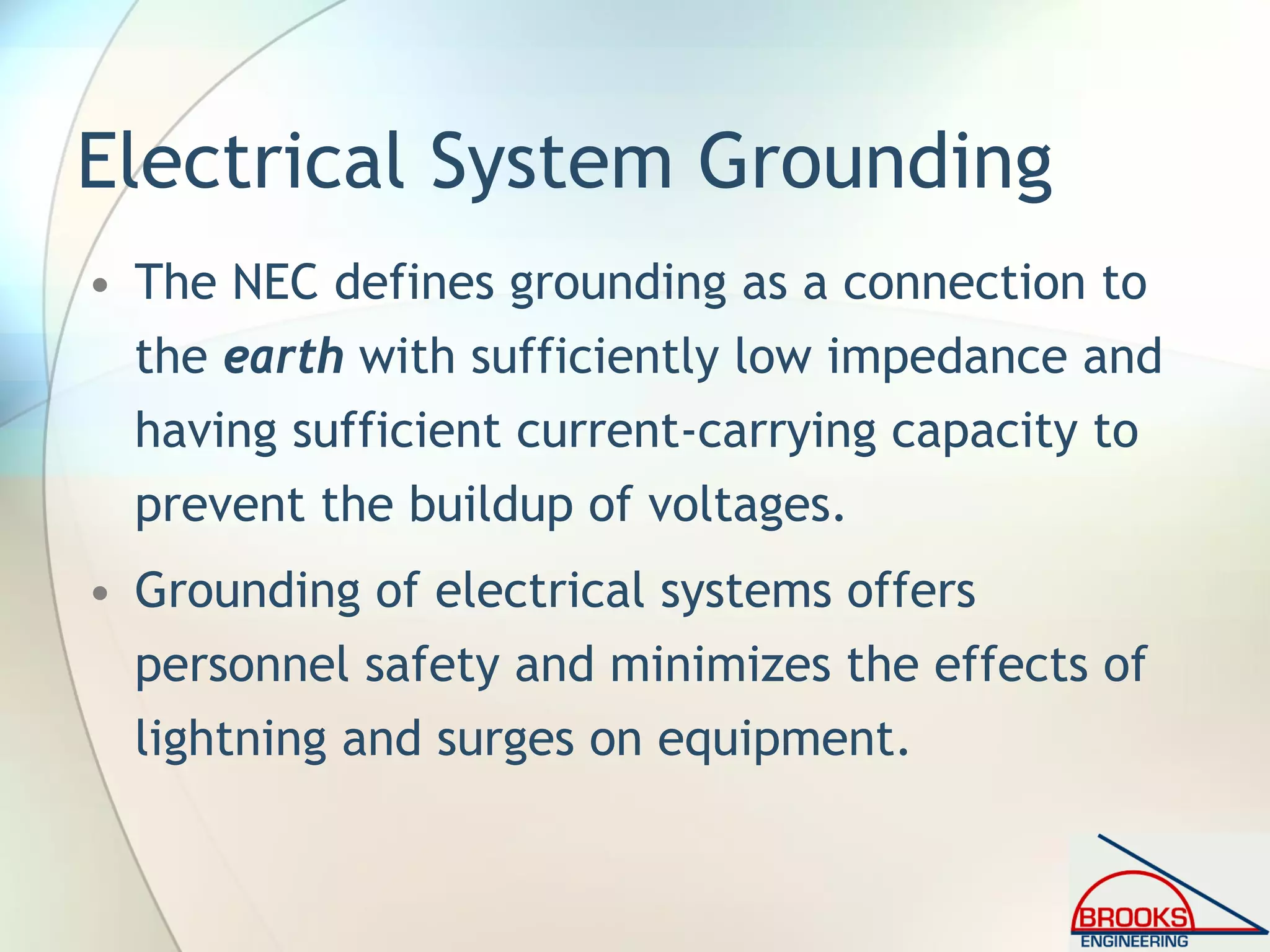

![690.43 Equipment Grounding
[2008 NEC]
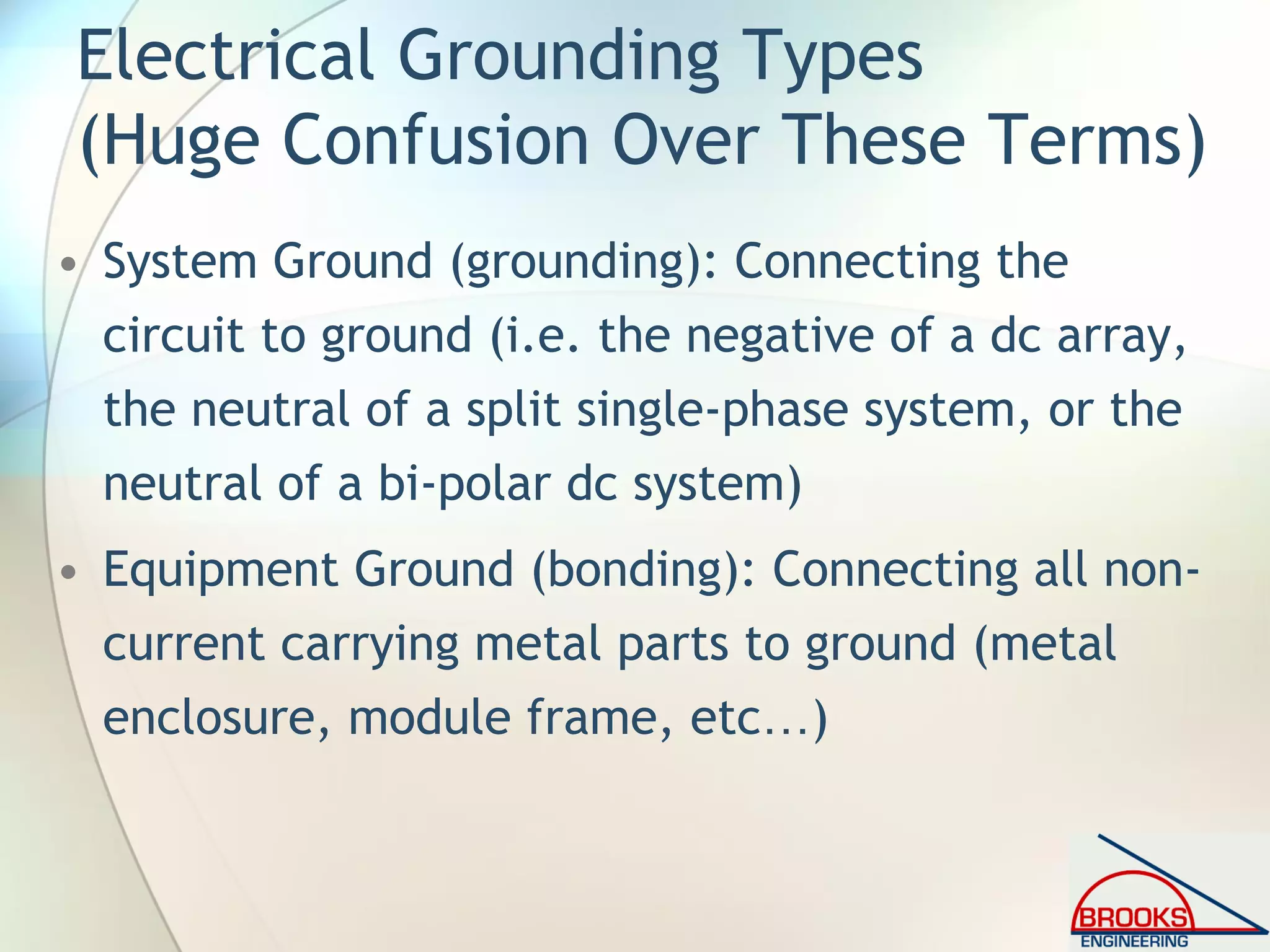
• “Devices listed and identified for grounding
the metallic frames of PV modules shall be
permitted to bond the exposed metallic
frames of PV modules to grounded
mounting structures. Devices identified and
listed for bonding the metallic frames of PV
modules shall be permitted to bond the
exposed metallic frames of PV modules to
the metallic frames of adjacent PV
modules.”](https://image.slidesharecdn.com/inspectingpvsystemsforcodecompliance-130831084458-phpapp01/75/Inspecting-Photovoltaic-PV-Systems-for-Code-Compliance-66-2048.jpg)

![I. General [2008 NEC]
690.4 (D) Equipment Installation
• “Inverters, motor generators, photovoltaic
modules, photovoltaic panels, ac photovoltaic
modules, source-circuit combiners, and charge
controllers intended for use in photovoltaic
power systems shall be identified and listed
for the application.”
• Modules listed to UL1703 (soon UL1730); all
combiners, controllers, and Inverters listed to
UL1741](https://image.slidesharecdn.com/inspectingpvsystemsforcodecompliance-130831084458-phpapp01/75/Inspecting-Photovoltaic-PV-Systems-for-Code-Compliance-74-2048.jpg)
![I. General [2008 NEC]
690.5 Ground-Fault Protection
• “Grounded dc photovoltaic arrays shall be
provided with dc ground-fault protection.”
• Exception No. 1: Ground-mounted or pole-mounted
photovoltaic arrays with not more than two
paralleled source circuits and with all dc source and
dc output circuits isolated from buildings
• Exception No. 2: PV arrays installed at other than
dwelling units shall be permitted without ground-
fault protection where the equipment grounding
conductors are sized in accordance with 690.45.](https://image.slidesharecdn.com/inspectingpvsystemsforcodecompliance-130831084458-phpapp01/75/Inspecting-Photovoltaic-PV-Systems-for-Code-Compliance-75-2048.jpg)
![I. General [2008 NEC]
690.5 Ground-Fault Protection (cont.)
• “Manual operation of the main PV dc
disconnect shall not activate the ground-fault
protection device or result in grounded
conductors becoming ungrounded.”
• GFP must either open all conductors or
deenergize the inverter output.](https://image.slidesharecdn.com/inspectingpvsystemsforcodecompliance-130831084458-phpapp01/75/Inspecting-Photovoltaic-PV-Systems-for-Code-Compliance-76-2048.jpg)
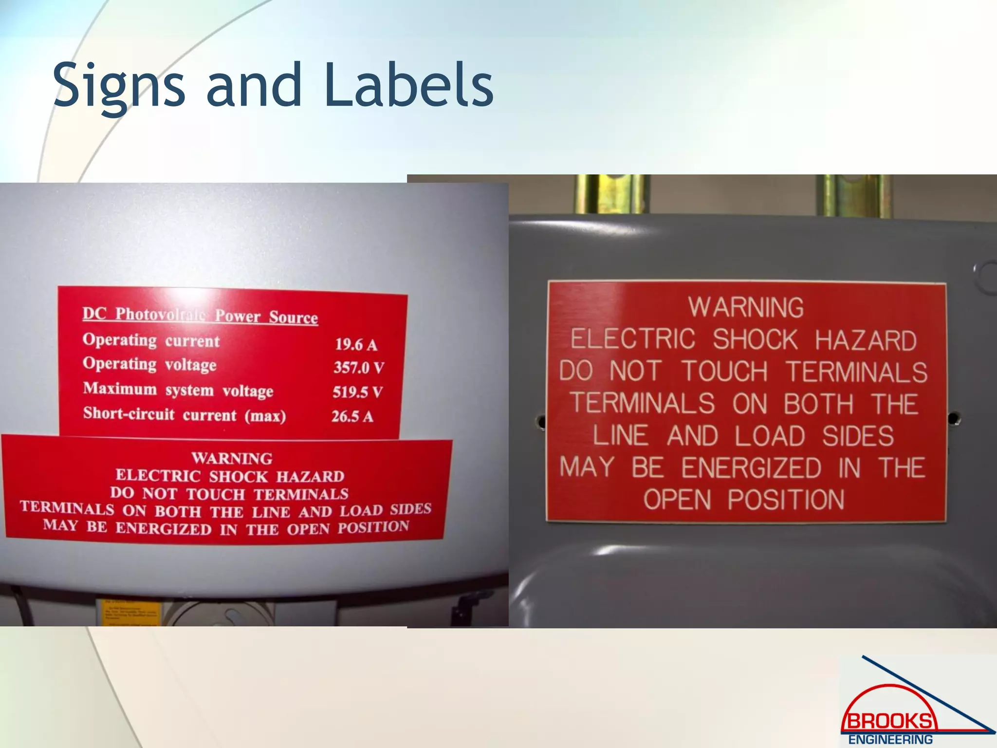
![I. General [2008 NEC]
690.5 (C) Labels and Markings
• Inverter and battery (if used) must have a sign
• A warning label shall appear on the utility-
interactive inverter or be applied by the
installer near the ground-fault indicator at a
visible location, stating the following:
• WARNING, ELECTRIC SHOCK HAZARD, IF A
GROUND FAULT IS INDICATED, NORMALLY
GROUNDED CONDUCTORS, MAY BE
UNGROUNDED AND ENERGIZED](https://image.slidesharecdn.com/inspectingpvsystemsforcodecompliance-130831084458-phpapp01/75/Inspecting-Photovoltaic-PV-Systems-for-Code-Compliance-77-2048.jpg)
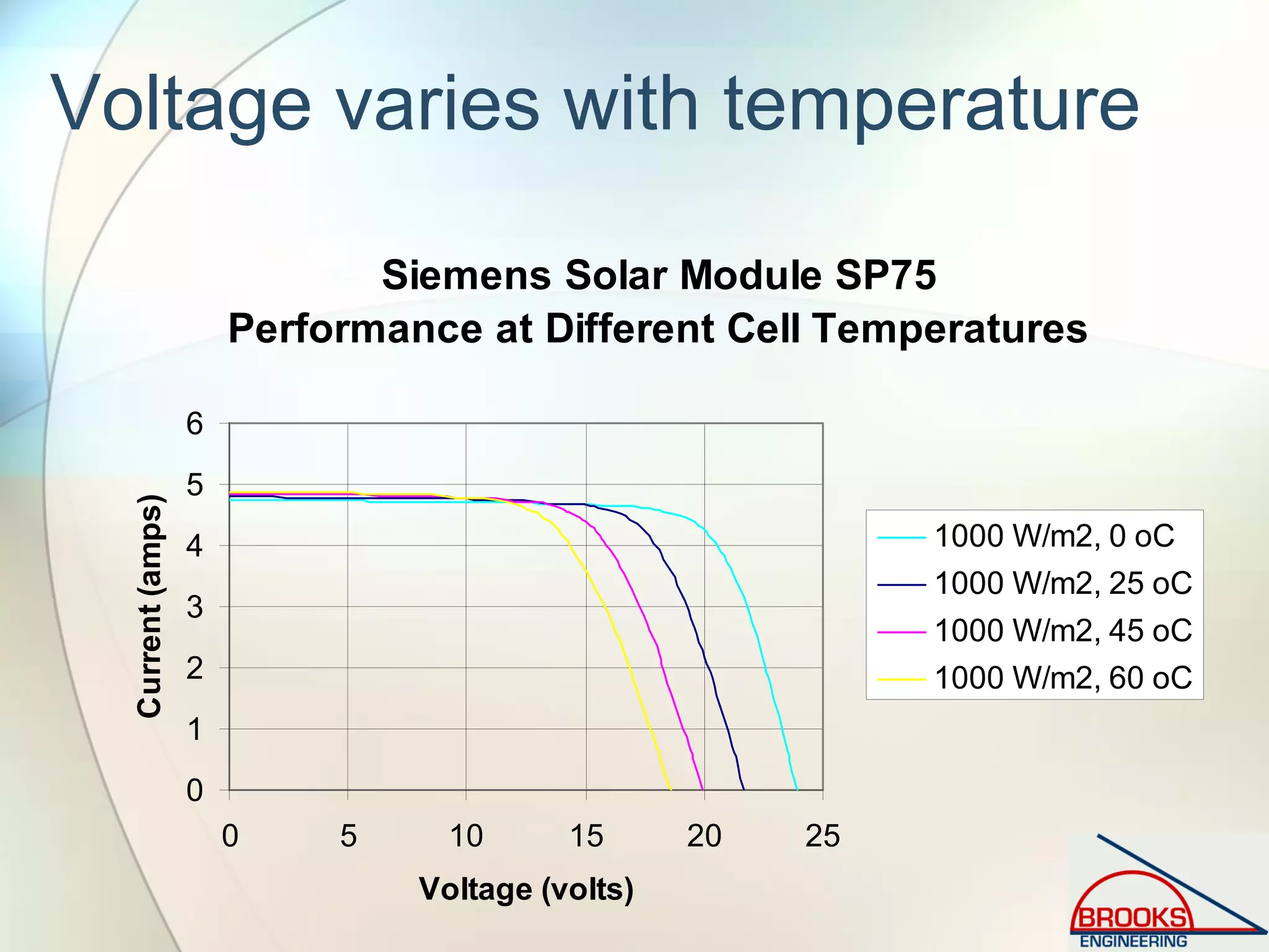
![II. Circuit Requirements [2008 NEC]
690.7 Maximum Voltage.
• New table and calculation option.
• Table 690.7 is now graduated in 4ºC increments.
• “When open-circuit voltage temperature
coefficients are supplied in the instructions for
listed PV modules, they shall be used to
calculate the maximum photovoltaic system
voltage as required by 110.3(B) instead of using
Table 690.7.”](https://image.slidesharecdn.com/inspectingpvsystemsforcodecompliance-130831084458-phpapp01/75/Inspecting-Photovoltaic-PV-Systems-for-Code-Compliance-78-2048.jpg)
![II. Circuit Requirements [2008 NEC]
690.7 Maximum Voltage.
• Example Calculation
• Shell SQ-175PC has a Voc Temperature Coefficient
in their literature of:
− αVoc = -129 mV/ºC; Voc =44.6V
− Coldest expected Temp=-25ºC; Rating @ 25ºC (STC)
• Vmax (per module) = 44.6V + [-129 mV/ºC x
(1V/1000mV) x (-25ºC–25ºC)] = 51.05 Volts.
• Table 690.7 [2008]: Vmax = 44.6V x 1.20 = 53.52V
• Table 690.7 [2005]: Vmax = 44.6V x 1.25 = 55.75V](https://image.slidesharecdn.com/inspectingpvsystemsforcodecompliance-130831084458-phpapp01/75/Inspecting-Photovoltaic-PV-Systems-for-Code-Compliance-79-2048.jpg)
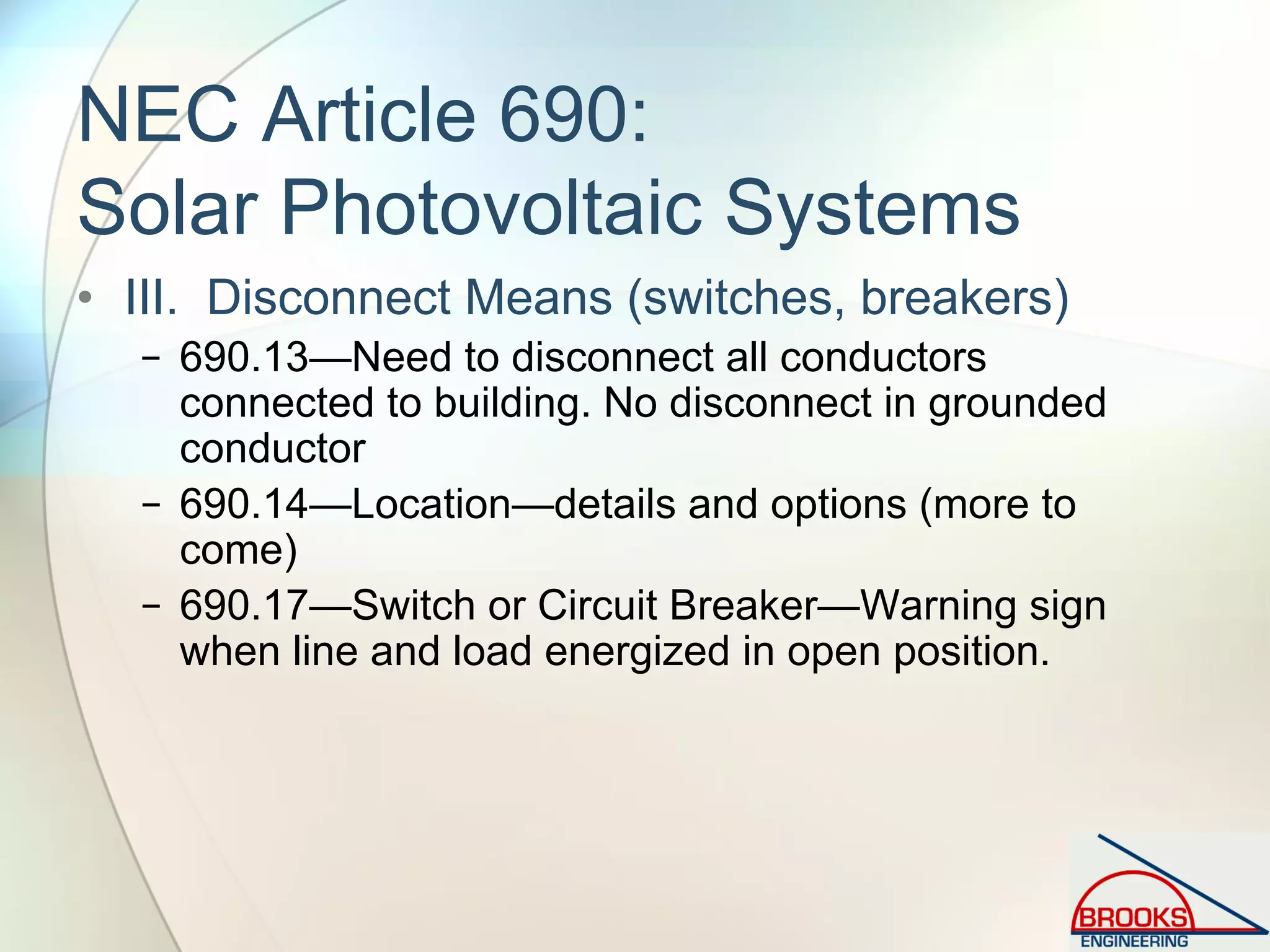
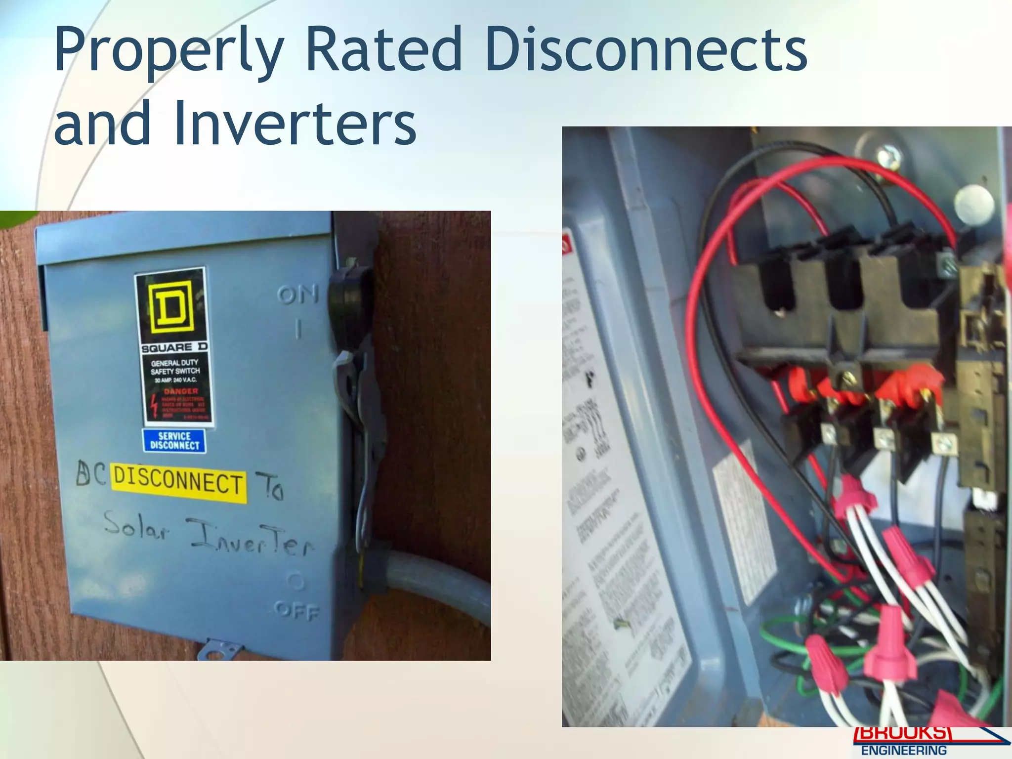
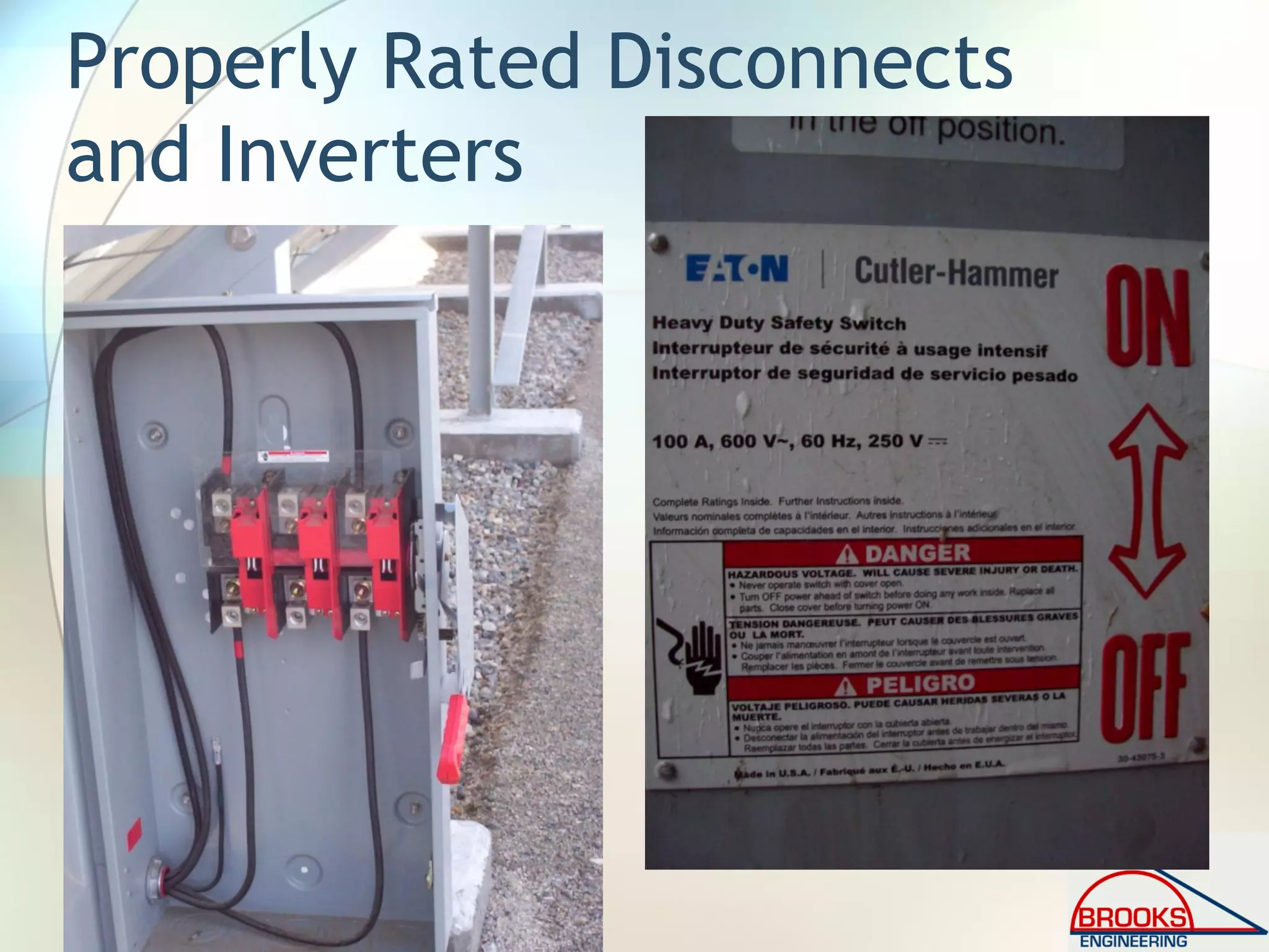
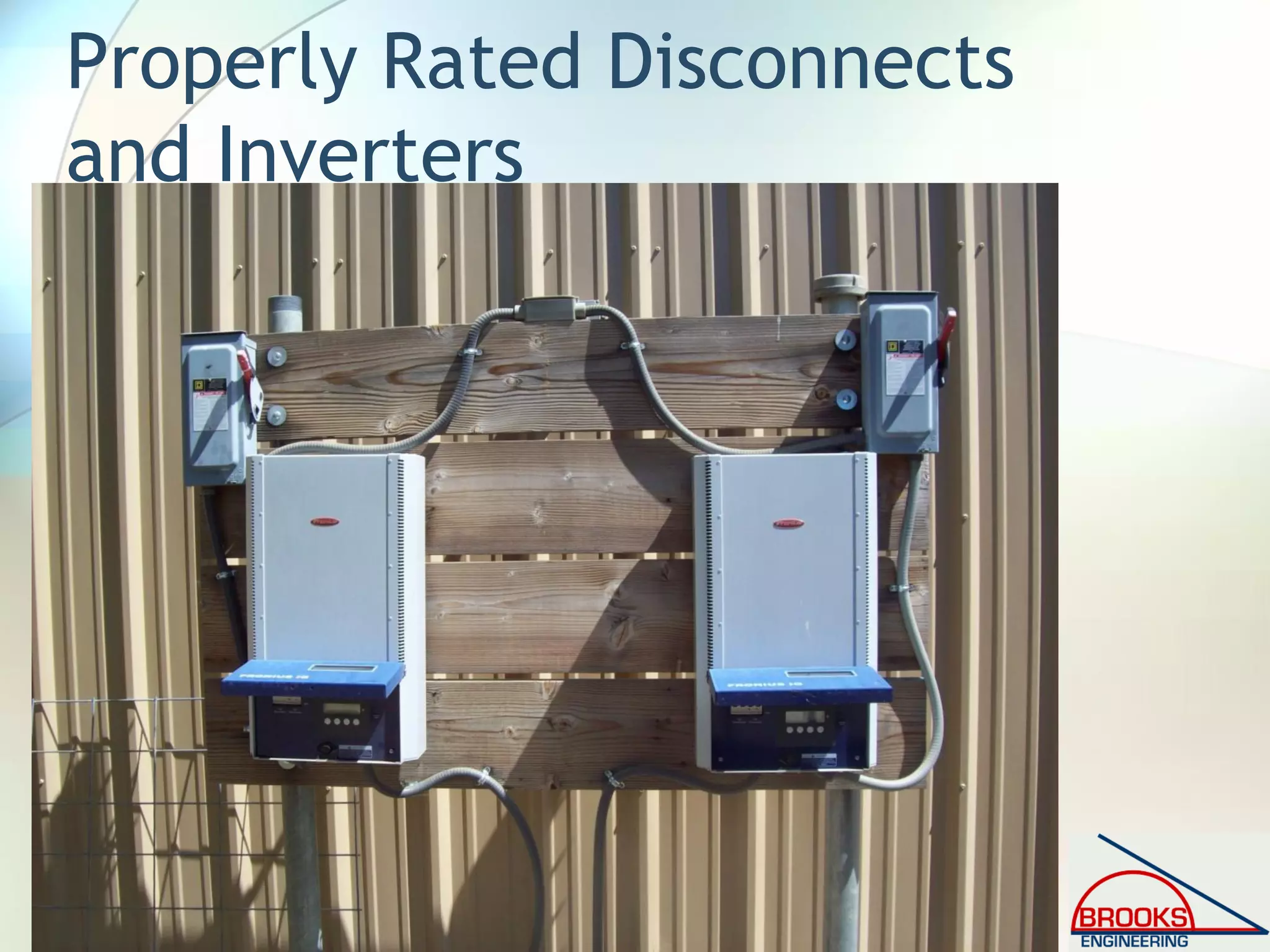
![III. Disconnecting Means [2005 NEC]
Article 690.14 (Additional Provisions)
• Clarification on location of PV Disconnecting Means and
Location of Inverters in Not-Readily-Accessible
Locations
• New Section (D) Utility-Interactive Inverters Mounted in
Not-Readily Accessible Locations. Utility-interactive
inverters shall be permitted to be mounted on roofs or
other exterior areas that are not readily accessible.
These installations shall comply with (1) through (4):
− (1) A direct-current photovoltaic disconnecting means shall be
mounted within sight of or in the inverter.
− (2) An alternating-current disconnecting means shall be
mounted within sight of or in the inverter.
− (3) The alternating-current output conductors from the inverter
and an additional alternating-current disconnecting means for
the inverter shall comply with 690.14(C)(1).
− (4) A plaque shall be installed in accordance with 705.10.](https://image.slidesharecdn.com/inspectingpvsystemsforcodecompliance-130831084458-phpapp01/75/Inspecting-Photovoltaic-PV-Systems-for-Code-Compliance-80-2048.jpg)
![Article 690.31 [2005 NEC]
Wiring Methods Permitted
• New 690.31(E) related to PV Output Circuits in
metallic raceways.
• “(E) Direct-Current Photovoltaic Source and Output
Circuits Inside a Building. Where direct current
photovoltaic source or output circuits of a utility-
interactive inverter from a building-integrated or
other photovoltaic system are run inside a building or
structure, they shall be contained in metallic
raceways or metal enclosures from the point of
penetration of the surface of the building or structure
to the first readily accessible disconnecting means.
The disconnecting means shall comply with 690.14(A)
through 690.14(D).”](https://image.slidesharecdn.com/inspectingpvsystemsforcodecompliance-130831084458-phpapp01/75/Inspecting-Photovoltaic-PV-Systems-for-Code-Compliance-81-2048.jpg)
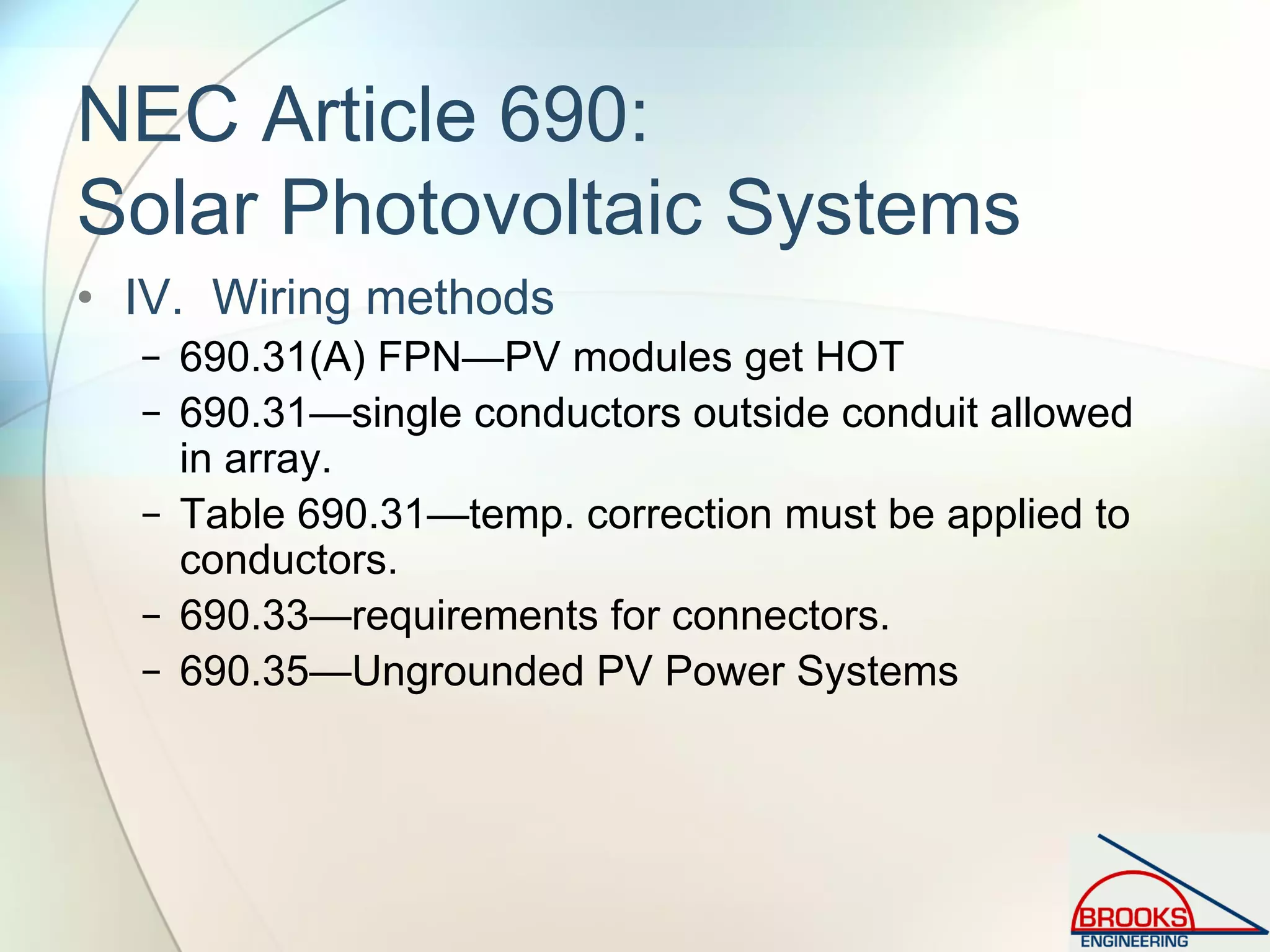
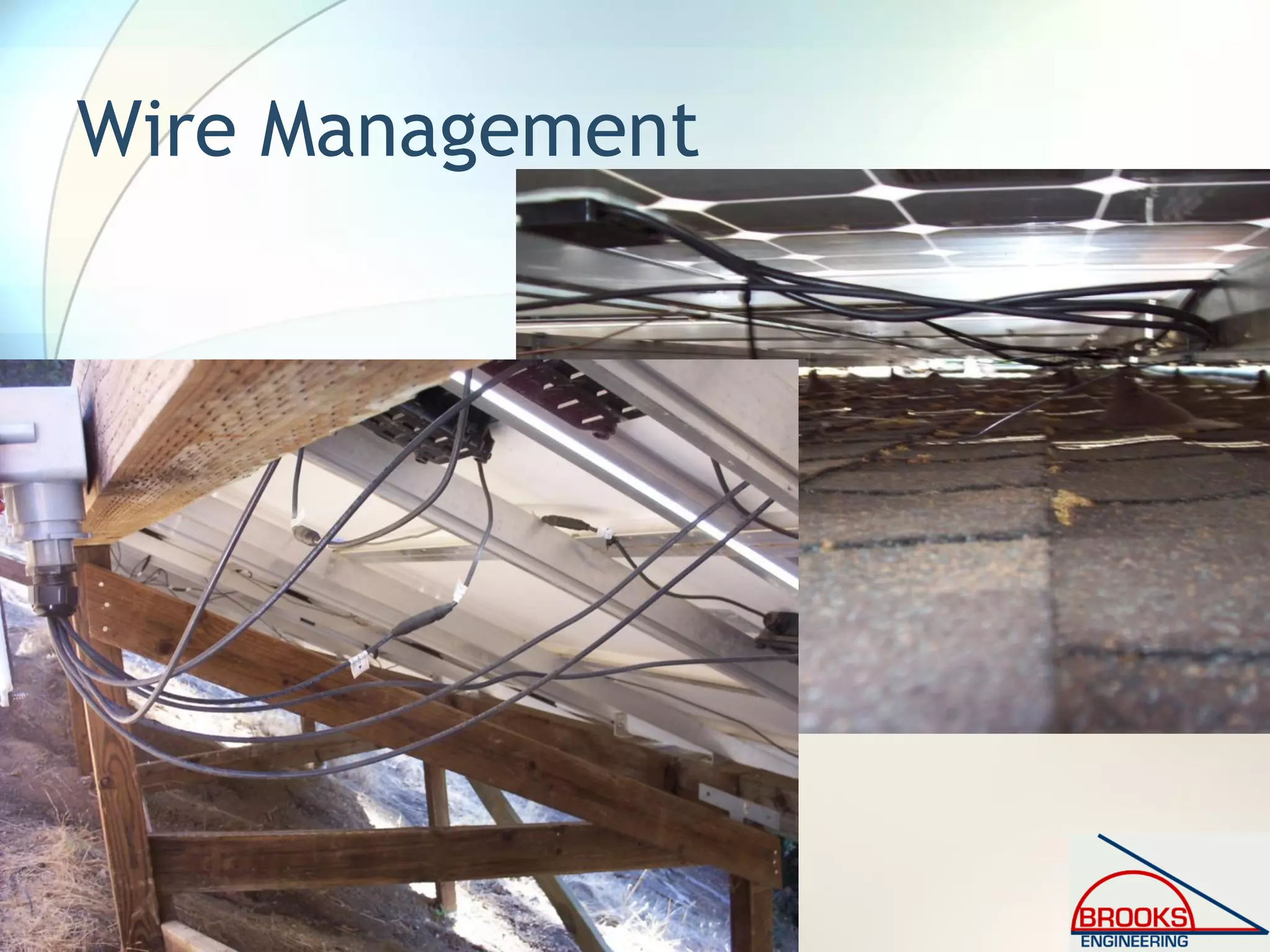
![Article 690.31 [2008 NEC]
Wiring Methods Permitted
• New language in 690.31(A) “Where
photovoltaic source and output circuits
operating at maximum system voltages
greater than 30 volts are installed in readily
accessible locations, circuit conductors shall
be installed in a raceway.”](https://image.slidesharecdn.com/inspectingpvsystemsforcodecompliance-130831084458-phpapp01/75/Inspecting-Photovoltaic-PV-Systems-for-Code-Compliance-82-2048.jpg)
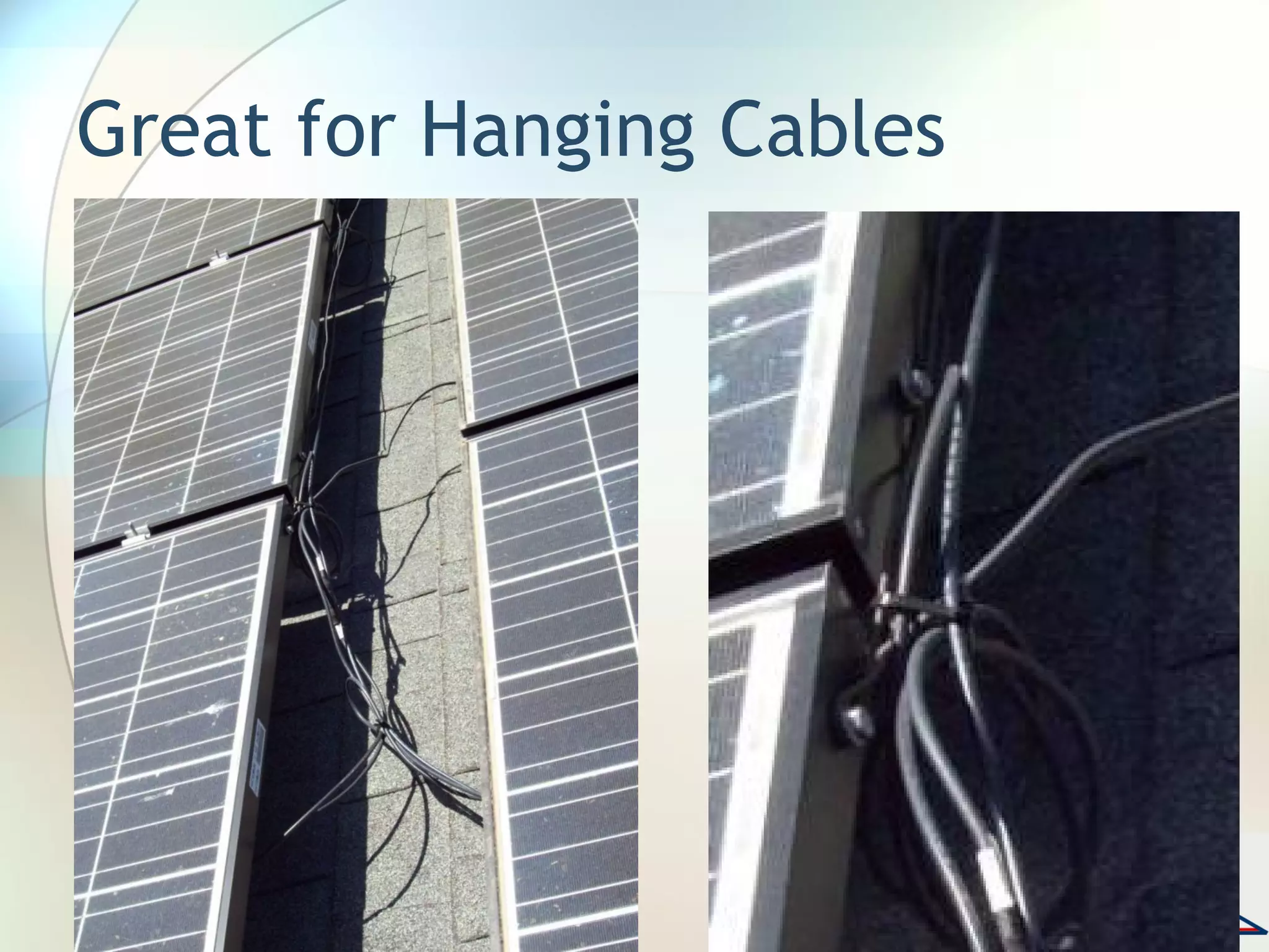
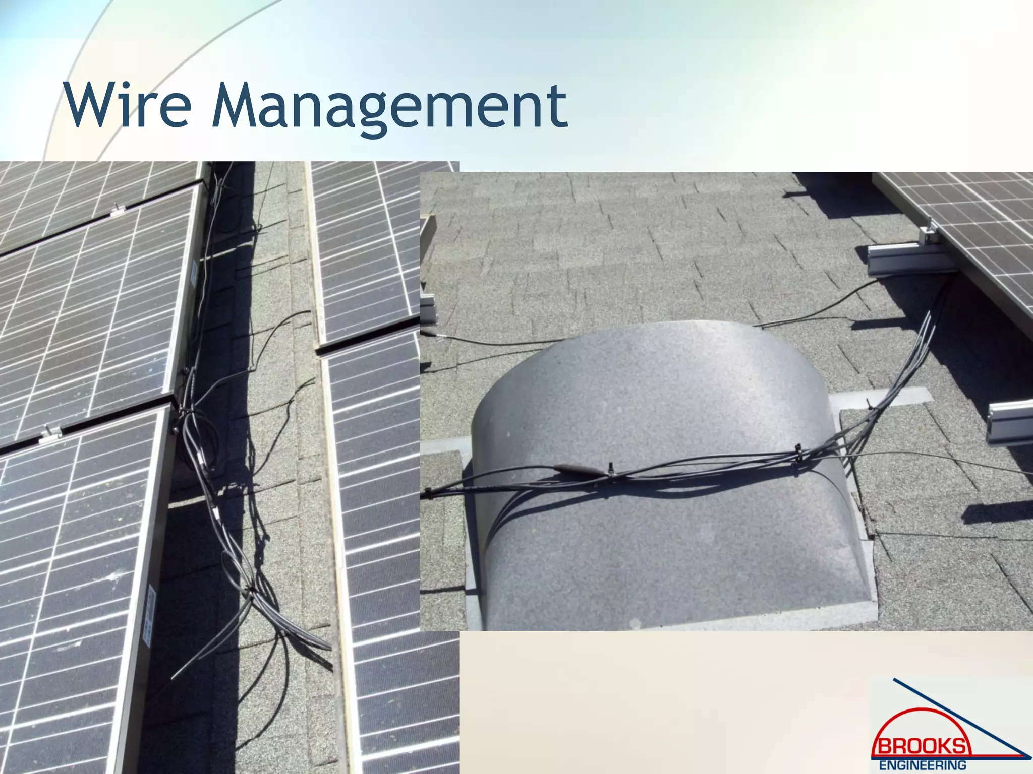
![Article 690.31 [2008 NEC]
Wiring Methods Permitted
• New language in 690.31(B)
• “(B) Single-Conductor Cable. Single-
conductor cable type USE-2, and single-
conductor cable listed and labeled as
photovoltaic (PV) wire shall be permitted in
exposed outdoor locations in photovoltaic
source circuits for photovoltaic module
interconnections within the photovoltaic
array. Exception: Raceways shall be used
when required by 690.31(A).”](https://image.slidesharecdn.com/inspectingpvsystemsforcodecompliance-130831084458-phpapp01/75/Inspecting-Photovoltaic-PV-Systems-for-Code-Compliance-83-2048.jpg)
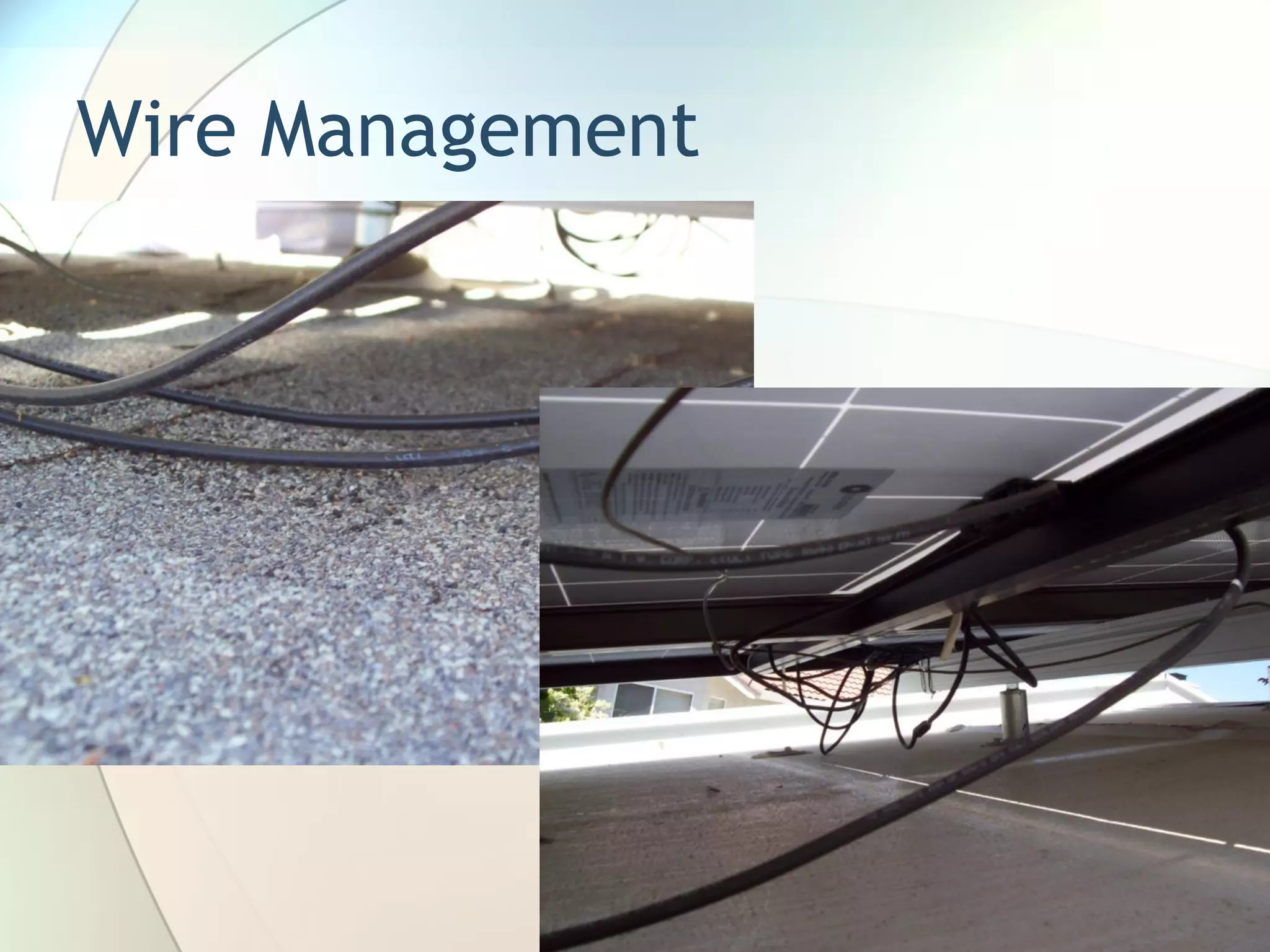
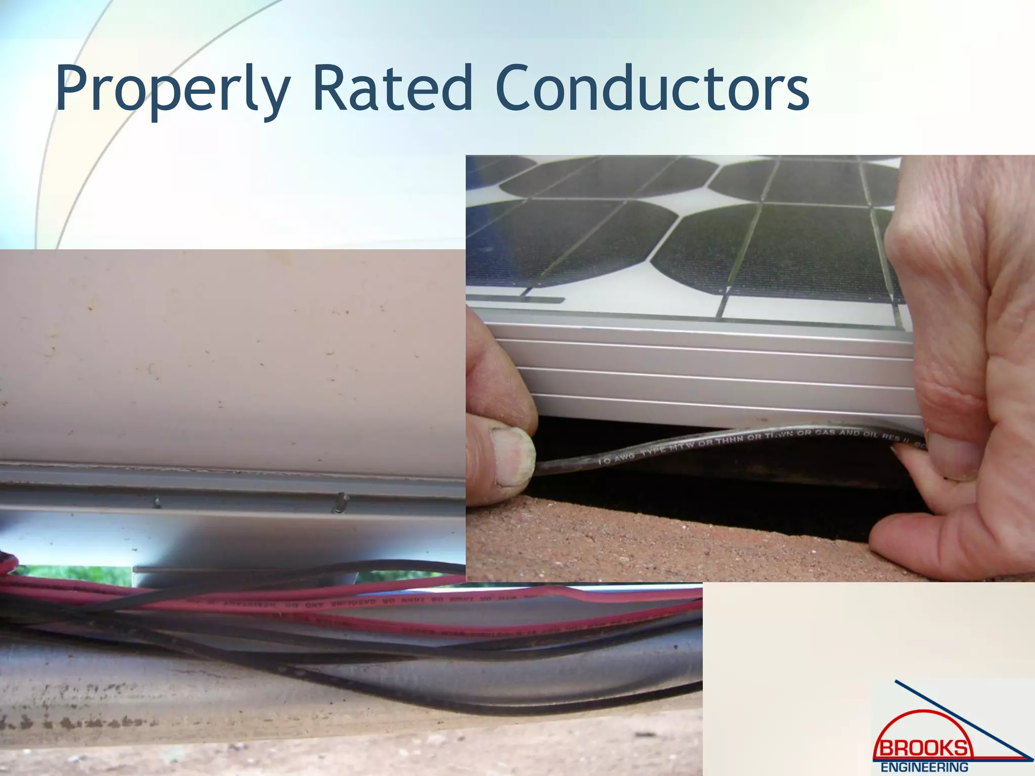
![Article 690.31 [2005 NEC]
Wiring Methods Permitted
• New Fine Print Note in 690.31(A)
− “FPN: Photovoltaic modules operate at
elevated temperatures when exposed to
high ambient temperatures and to bright
sunlight. These temperatures may
routinely exceed 70°C (158°F) in many
locations. Module interconnection
conductors are available with insulation
rated for wet locations and a temperature
rating of 90°C (194°F) or greater.”](https://image.slidesharecdn.com/inspectingpvsystemsforcodecompliance-130831084458-phpapp01/75/Inspecting-Photovoltaic-PV-Systems-for-Code-Compliance-84-2048.jpg)
![Side Note on Temperature
310.10 FPN No. 2 [2005 NEC]
• New Fine Print Note (below)
− “FPN No. 2: Conductors installed in
conduit exposed to direct sunlight in
close proximity to rooftops have been
shown, under certain conditions, to
experience a temperature rise of 17°C
(30°F) above ambient temperature on
which the ampacity is based.”](https://image.slidesharecdn.com/inspectingpvsystemsforcodecompliance-130831084458-phpapp01/75/Inspecting-Photovoltaic-PV-Systems-for-Code-Compliance-85-2048.jpg)
![Side Note on Temperature
310.15(B)(2)[2008 NEC]
• “(c) Conduits Exposed to Sunlight on Rooftops.
Where conductors or cables are installed in
conduits exposed to direct sunlight on or above
rooftops, the adjustments shown in Table
310.15(B)(2)(c) shall be added to the outdoor
temperature to determine the applicable ambient
temperature for application of the correction
factors in Table 310.16 and Table 310.18.
FPN: One source for the average ambient
temperatures in various locations is the ASHRAE
handbook — Fundamentals.”](https://image.slidesharecdn.com/inspectingpvsystemsforcodecompliance-130831084458-phpapp01/75/Inspecting-Photovoltaic-PV-Systems-for-Code-Compliance-86-2048.jpg)
![Side Note on Temperature
310.15(B)(2)[2008 NEC]
• Table 310.15(B)(2)(c) Ambient Temperature
Adjustment for Conduits Exposed to Sunlight On
or Above Rooftops Temperature Adder
Distance Above Roof to Bottom of Conduit °C °F
0 – 13 mm (1⁄2 in.) 33 60
Above 13 mm (1⁄2 in.) – 90 mm (31⁄2 in.) 22 40
Above 90 mm (31⁄2 in.) – 300 mm (12 in.) 17 30
Above 300 mm (12 in.) – 900 mm (36 in.) 14 25](https://image.slidesharecdn.com/inspectingpvsystemsforcodecompliance-130831084458-phpapp01/75/Inspecting-Photovoltaic-PV-Systems-for-Code-Compliance-87-2048.jpg)
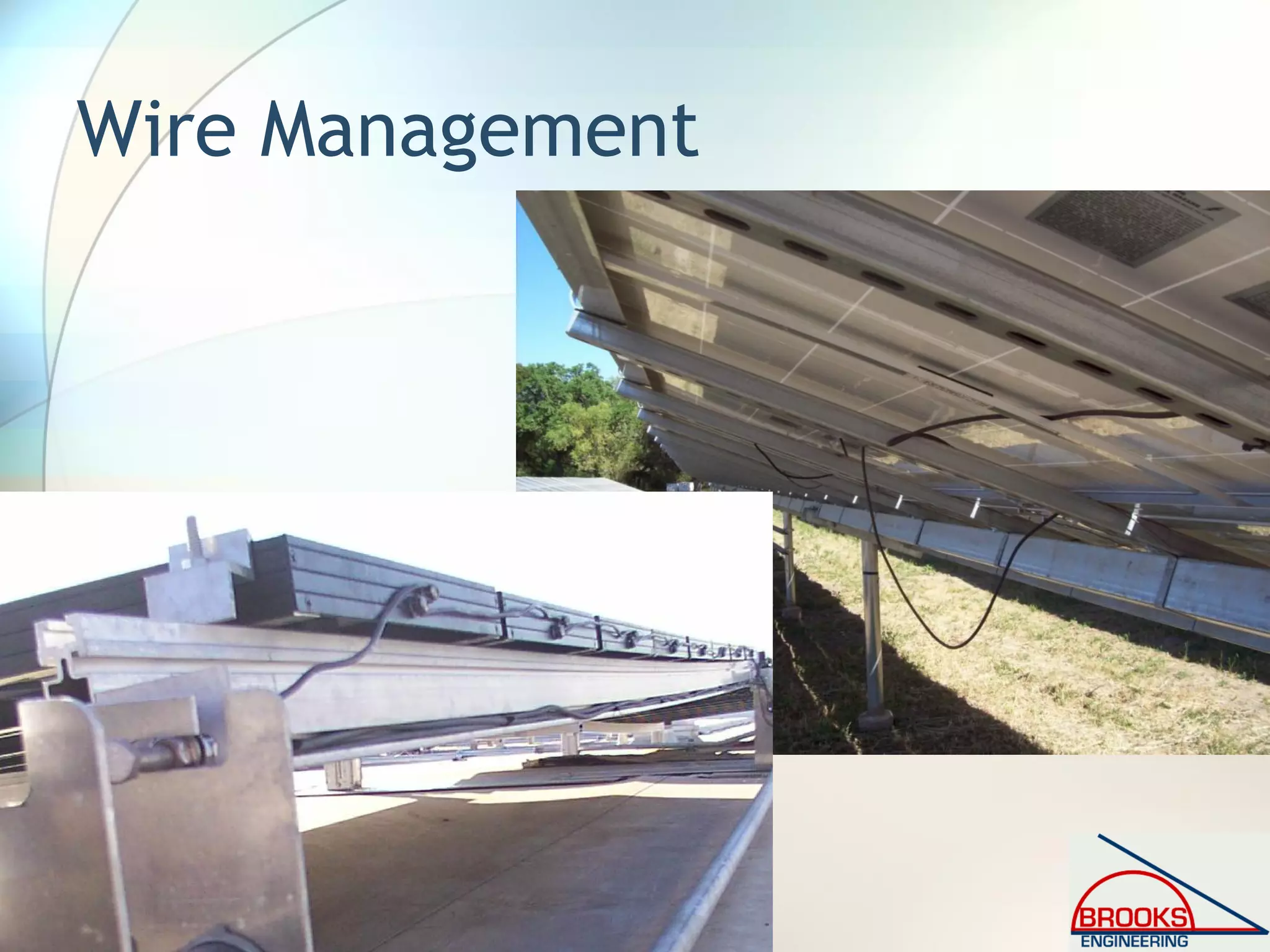
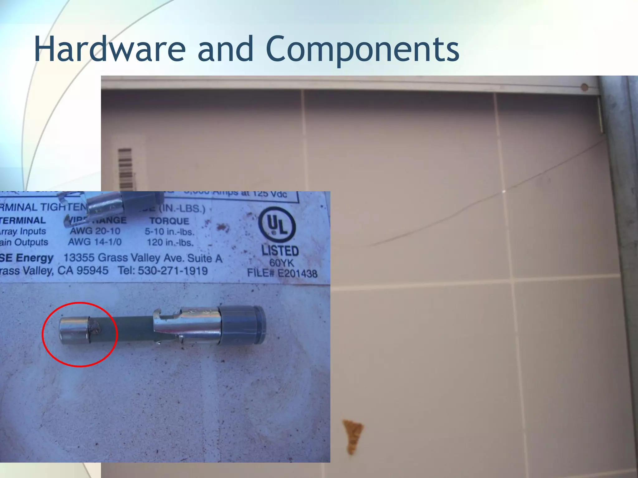
![Article 690.31 [2008 NEC]
Wiring Methods Permitted
• New language in 690.31(F)
• “(F) Flexible, Fine-Stranded Cables.
Flexible, finestranded cables shall be
terminated only with terminals, lugs,
devices, or connectors that are identified
and listed for such use.”](https://image.slidesharecdn.com/inspectingpvsystemsforcodecompliance-130831084458-phpapp01/75/Inspecting-Photovoltaic-PV-Systems-for-Code-Compliance-88-2048.jpg)
![Article 690.33 [2008 NEC]
Connectors
• New language in 690.33(F)
• “(E) Interruption of Circuit. Connectors shall
be either (1) or (2):
• (1) Be rated for interrupting current without
hazard to the operator.
• (2) Be a type that requires the use of a tool to
open and marked “Do Not Disconnect Under
Load” or “Not for Current Interrupting.” ”](https://image.slidesharecdn.com/inspectingpvsystemsforcodecompliance-130831084458-phpapp01/75/Inspecting-Photovoltaic-PV-Systems-for-Code-Compliance-89-2048.jpg)
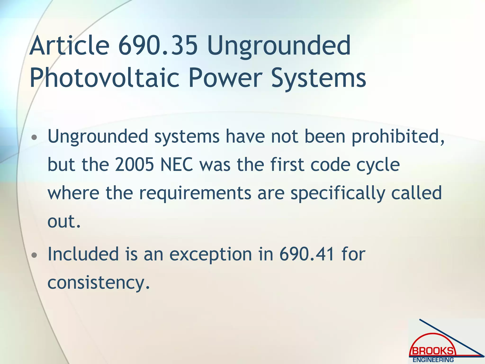
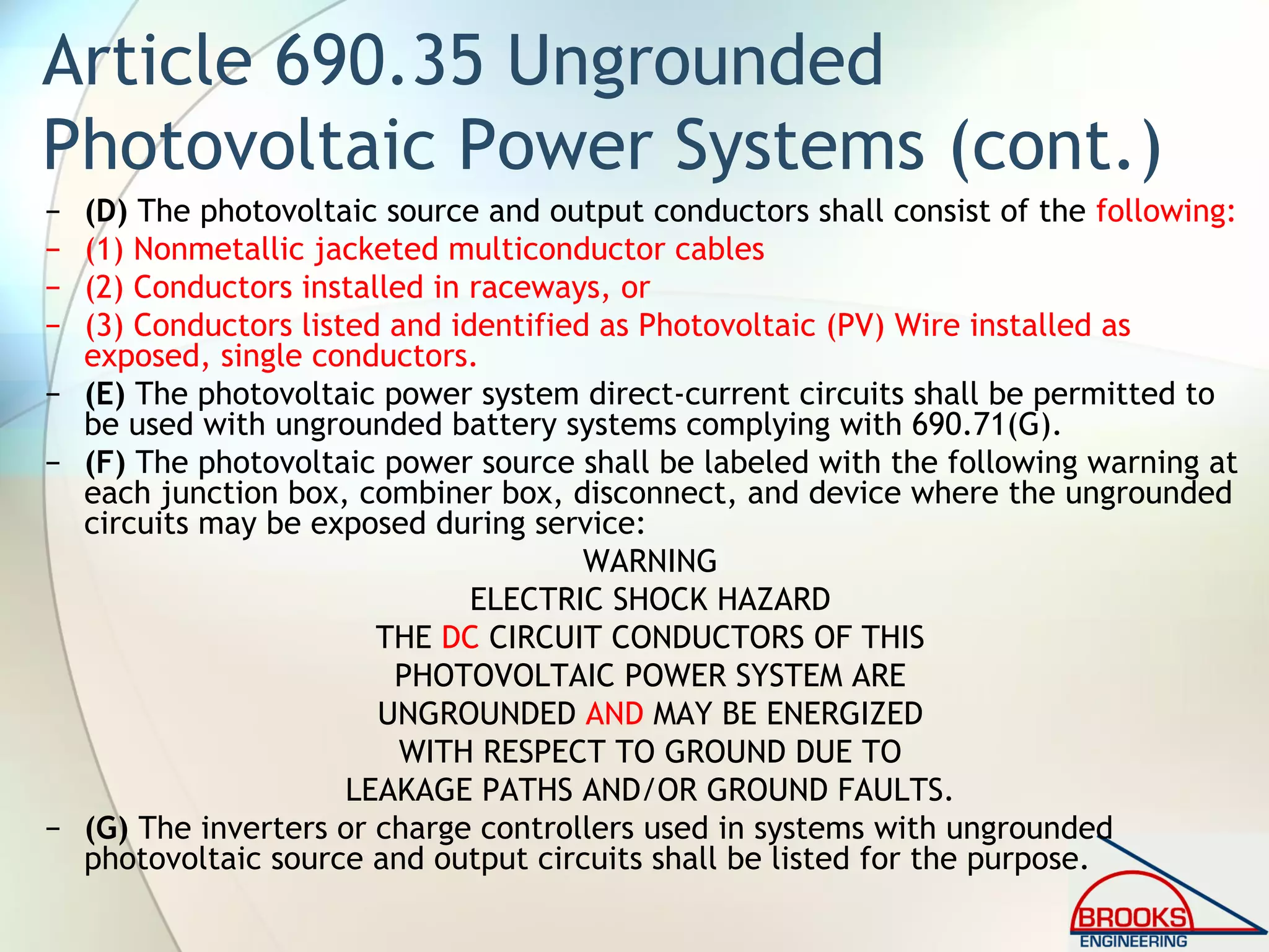
![Article 690.35 Ungrounded
Photovoltaic Power Systems [2005, 2008]
• “Photovoltaic power systems shall be permitted to
operate with ungrounded photovoltaic source and
output circuits where the system complies with
690.35(A) through 690.35(G).
− (A) Disconnects. All photovoltaic source and output circuit
conductors shall have disconnects complying with 690, Part III.
− (B) Overcurrent Protection. All photovoltaic source and output
circuit conductors shall have overcurrent protectioncomplying
with 690.9.
− (C) Ground-Fault Protection. All photovoltaic source and
output circuits shall be provided with a ground-fault protection
device or system that complies with (1) through (3):
• (1) Detects a ground fault.
• (2) Indicates that a ground fault has occurred
• (3) Automatically disconnects all conductors or causes the inverter
or charge controller connected to the faulted circuit to
automatically cease supplying power to output circuits.](https://image.slidesharecdn.com/inspectingpvsystemsforcodecompliance-130831084458-phpapp01/75/Inspecting-Photovoltaic-PV-Systems-for-Code-Compliance-91-2048.jpg)
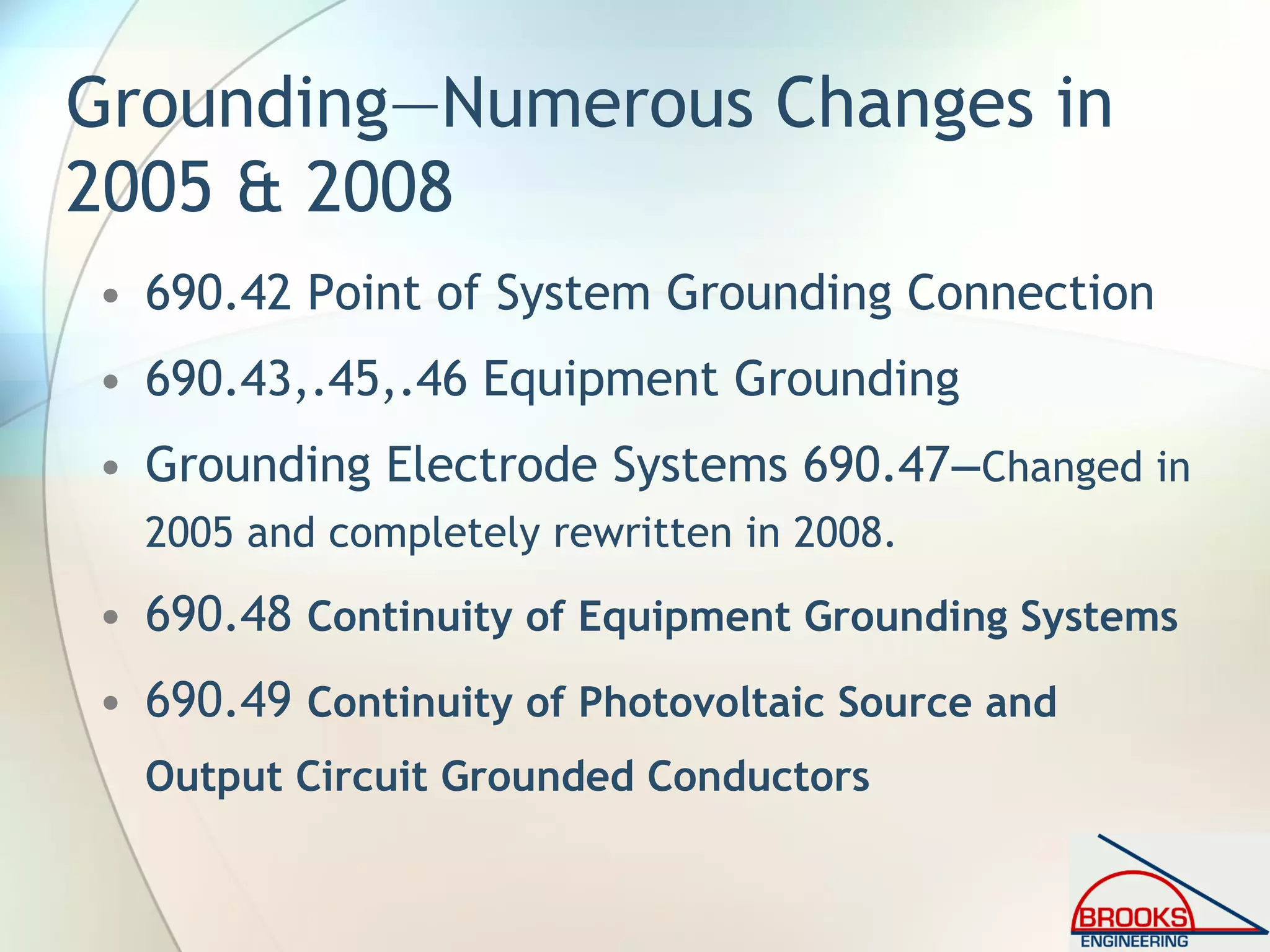
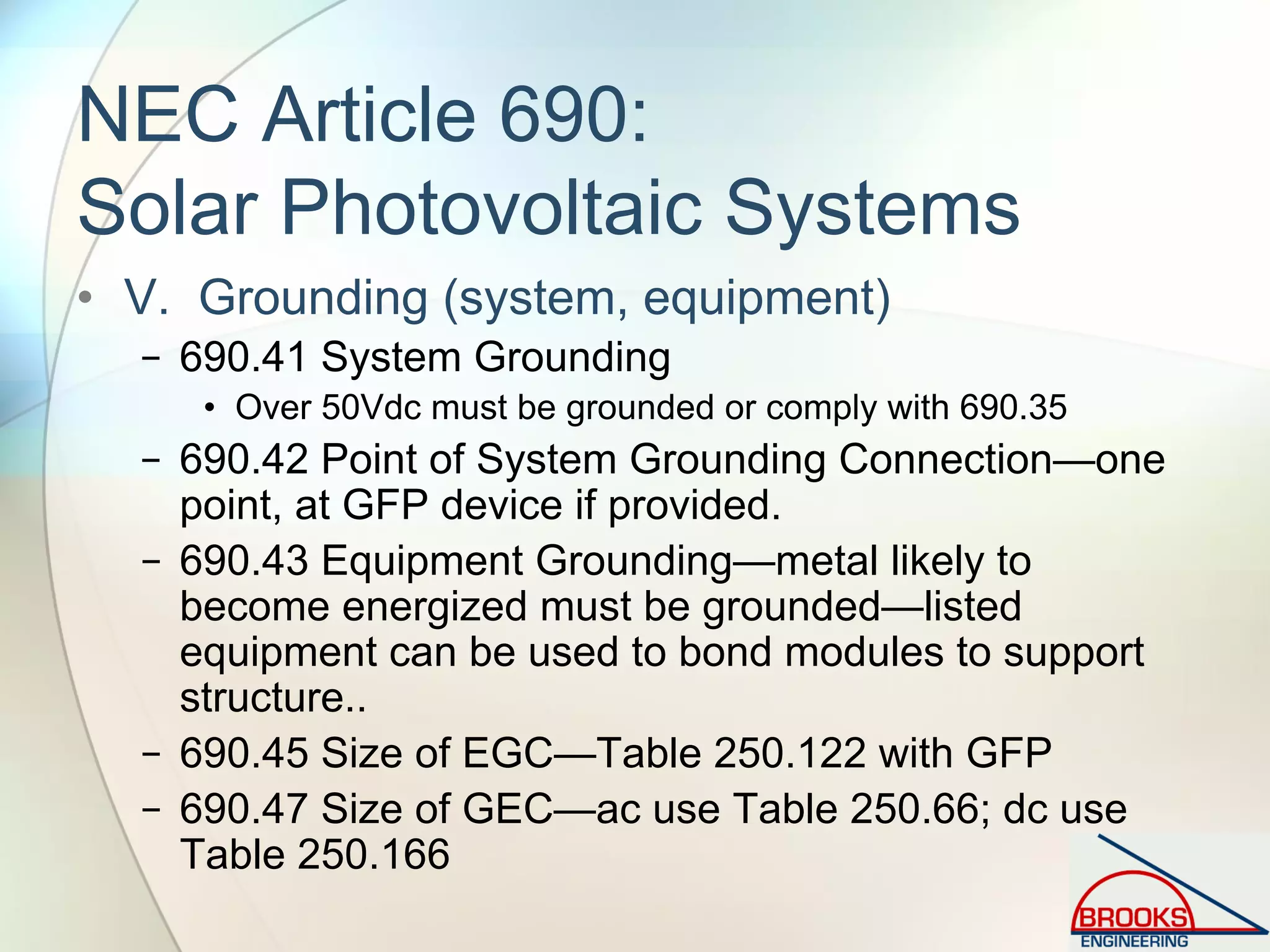
![690.42 Point of System
Grounding Connection [2008 NEC]
• Misleading FPN needed more information:
• FPN: Locating the grounding connection point as close as
practicable to the photovoltaic source better protects
the system from voltage surges due to lightning.
• “Exception: Systems with a 690.5 ground-fault
protection device shall be permitted to have the
required grounded conductor-to-ground bond
made by the ground-fault protection device. This
bond, where internal to the ground-fault
equipment, shall not be duplicated with an
external connection.”](https://image.slidesharecdn.com/inspectingpvsystemsforcodecompliance-130831084458-phpapp01/75/Inspecting-Photovoltaic-PV-Systems-for-Code-Compliance-94-2048.jpg)
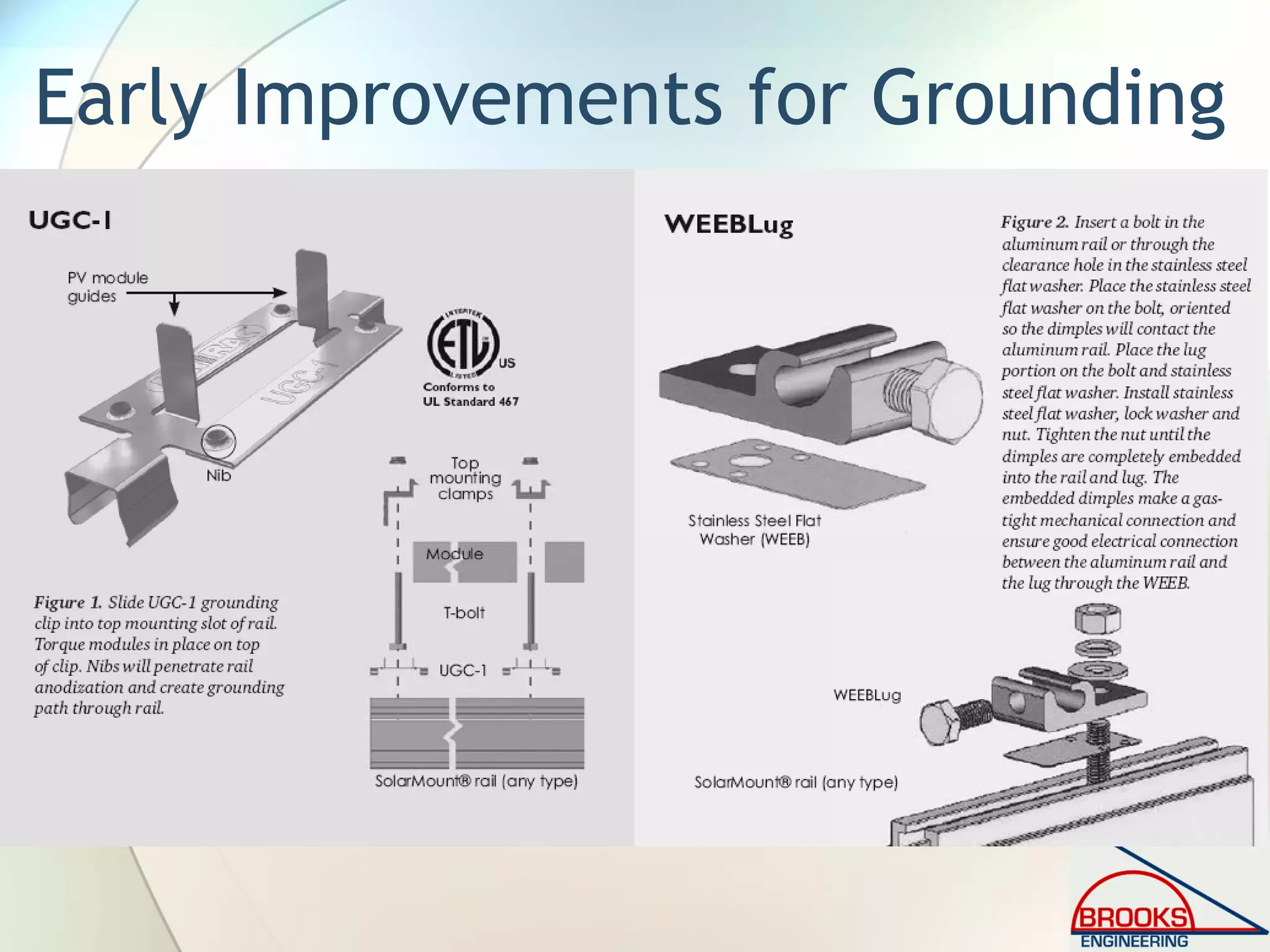
![690.43 Equipment Grounding
[2008 NEC]
• “Equipment grounding conductors for the
PV array and structure (where installed)
shall be contained within the same raceway
or cable, or otherwise run with the PV array
circuit conductors when those circuit
conductors leave the vicinity of the PV
array”](https://image.slidesharecdn.com/inspectingpvsystemsforcodecompliance-130831084458-phpapp01/75/Inspecting-Photovoltaic-PV-Systems-for-Code-Compliance-95-2048.jpg)
![690.45 Size of Equipment
Grounding Conductors [2008 NEC]
(Size matters—or maybe not)
• “(A) General. Equipment grounding conductors in
photovoltaic source and photovoltaic output
circuits shall be sized in accordance with Table
250.122. Where no overcurrent protective device
is used in the circuit, an assumed overcurrent
device rated at the photovoltaic rated shortcircuit
current shall be used in Table 250.122. Increases
in equipment grounding conductor size to address
voltage drop considerations shall not be required.
The equipment grounding conductors shall be no
smaller than 14 AWG.”](https://image.slidesharecdn.com/inspectingpvsystemsforcodecompliance-130831084458-phpapp01/75/Inspecting-Photovoltaic-PV-Systems-for-Code-Compliance-96-2048.jpg)
![690.45 Size of Equipment
Grounding Conductors [2008 NEC]
• “(B) Ground-Fault Protection Not Provided. For
other than dwelling units where ground-fault
protection is not provided in accordance with
690.5(A) through (C), each equipment grounding
conductor shall have an ampacity of at least two
(2) times the temperature and conduit fill
corrected circuit conductor ampacity”
• Enjoy reading the FPN…. Faults 3-5 series strings might
not blow string fuse so EGC must be oversized when no
GFP is provided—generally irrelevant.](https://image.slidesharecdn.com/inspectingpvsystemsforcodecompliance-130831084458-phpapp01/75/Inspecting-Photovoltaic-PV-Systems-for-Code-Compliance-97-2048.jpg)
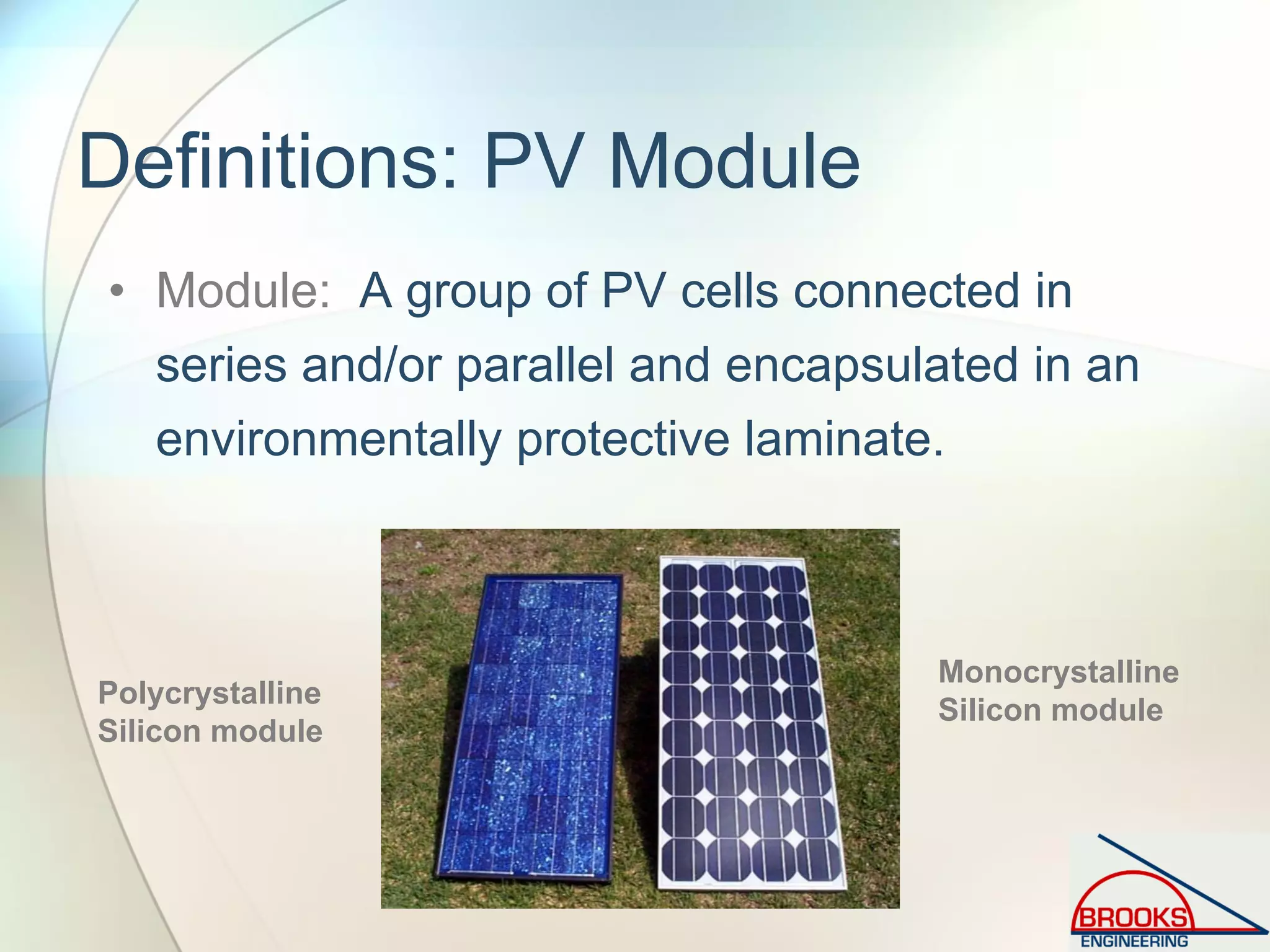
![690.46 Array Equipment
Grounding Conductors.[2008 NEC]
• “Equipment grounding conductors for photovoltaic
modules smaller than 6 AWG shall comply with
250.120(C).”
• This matches new language at the beginning of 690.43
that states, “An equipment grounding conductor between
a PV array and other equipment shall be required in
accordance with 250.110.”](https://image.slidesharecdn.com/inspectingpvsystemsforcodecompliance-130831084458-phpapp01/75/Inspecting-Photovoltaic-PV-Systems-for-Code-Compliance-98-2048.jpg)
![690.47(C) Systems with Alternating-Current
and Direct-Current Grounding Requirements
[2005 NEC]
• “Photovoltaic power systems with both alternating-
current and direct-current (dc) grounding requirements
shall be permitted to be grounded as described in (1) or
(2):
− (1) A grounding-electrode conductor shall be connected between
the identified dc grounding point to a separate dc grounding
electrode. The dc grounding-electrode conductor shall be sized
according to 250.166. The dc grounding electrode shall be
bonded to the ac grounding electrode to make a grounding
electrode system according to 250.52 and 250.53. The bonding
conductor shall be no smaller than the largest grounding
electrode conductor, either ac or dc.
− (2) The dc grounding electrode conductor and ac grounding
electrode conductor shall be connected to a single grounding
electrode. The separate grounding electrode conductors shall be
sized as required by 250.66 (ac) and 250.166 (dc).”](https://image.slidesharecdn.com/inspectingpvsystemsforcodecompliance-130831084458-phpapp01/75/Inspecting-Photovoltaic-PV-Systems-for-Code-Compliance-99-2048.jpg)
![690.47(C) Systems with Alternating-Current
and Direct-Current Grounding Requirements
[2008 NEC]
• 2008 NEC has 8 qualifying provisions to “assist” in specifying
the grounding requirements.
• Attempt is to reduce the required size of grounding
electrode conductor for utility-interactive inverters with
GFP.
• The requirements are difficult to follow and do not
encourage straightforward enforcement of provisions.
• Some have expressed concern over using an equipment
grounding conductor to serve the purpose of the grounding
electrode conductor given the less-stringent fastening
requirements of equipment grounds (2008 NEC Handbook).](https://image.slidesharecdn.com/inspectingpvsystemsforcodecompliance-130831084458-phpapp01/75/Inspecting-Photovoltaic-PV-Systems-for-Code-Compliance-100-2048.jpg)
![690.47(D) Additional Electrodes for Array
Grounding [2008 NEC]
• “Grounding electrodes shall be installed in
accordance with 250.52 at the location of all ground-
and pole-mounted photovoltaic arrays and as close as
practicable to the location of roof-mounted
photovoltaic arrays. The electrodes shall be
connected directly to the array frame(s) or
structure.”
− GEC from array frames to electrode sized to 250.166
− No substitute for equipment grounding conductor
− Ground-mount structure meeting 250.52 complies
− Roof-mounted may use building steel meeting 250.52(A)(2)
• Exception 1—Arrays with integral loads (area lights)
• Exception 2—If closer than 6’ from existing electrode](https://image.slidesharecdn.com/inspectingpvsystemsforcodecompliance-130831084458-phpapp01/75/Inspecting-Photovoltaic-PV-Systems-for-Code-Compliance-101-2048.jpg)
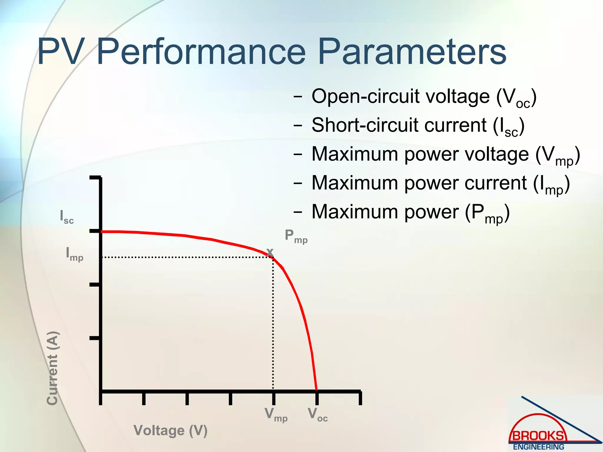
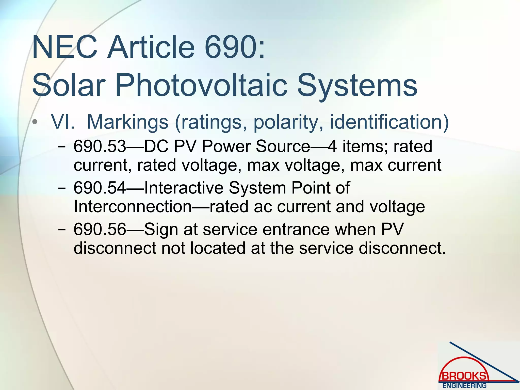
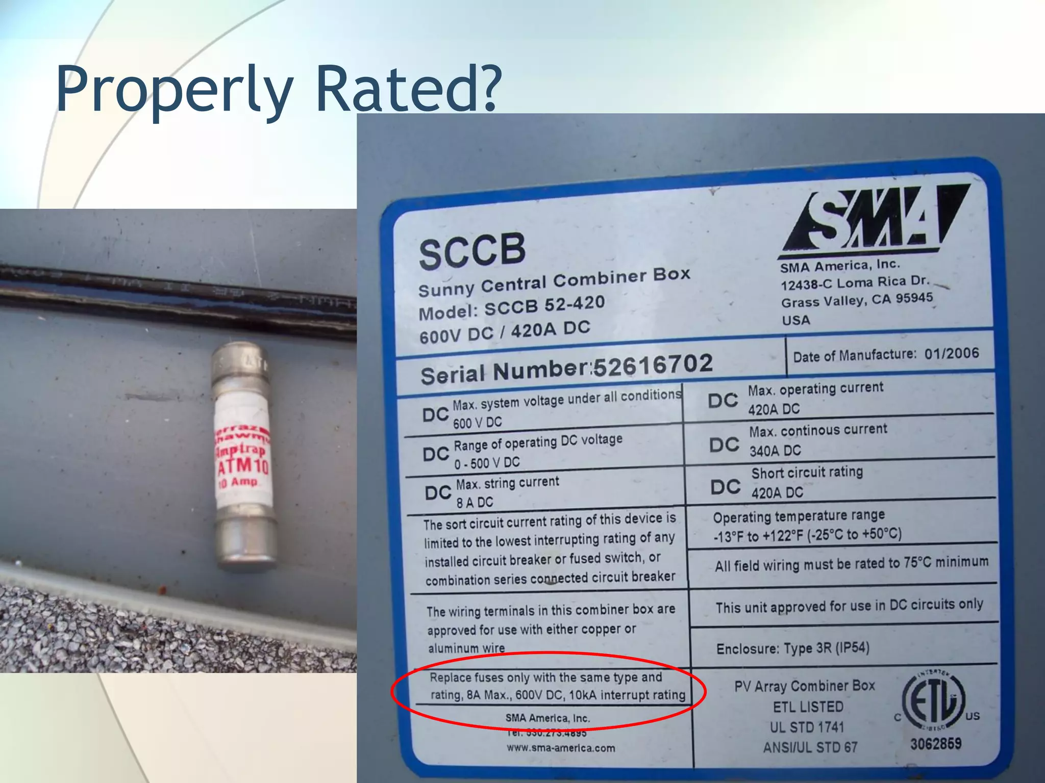
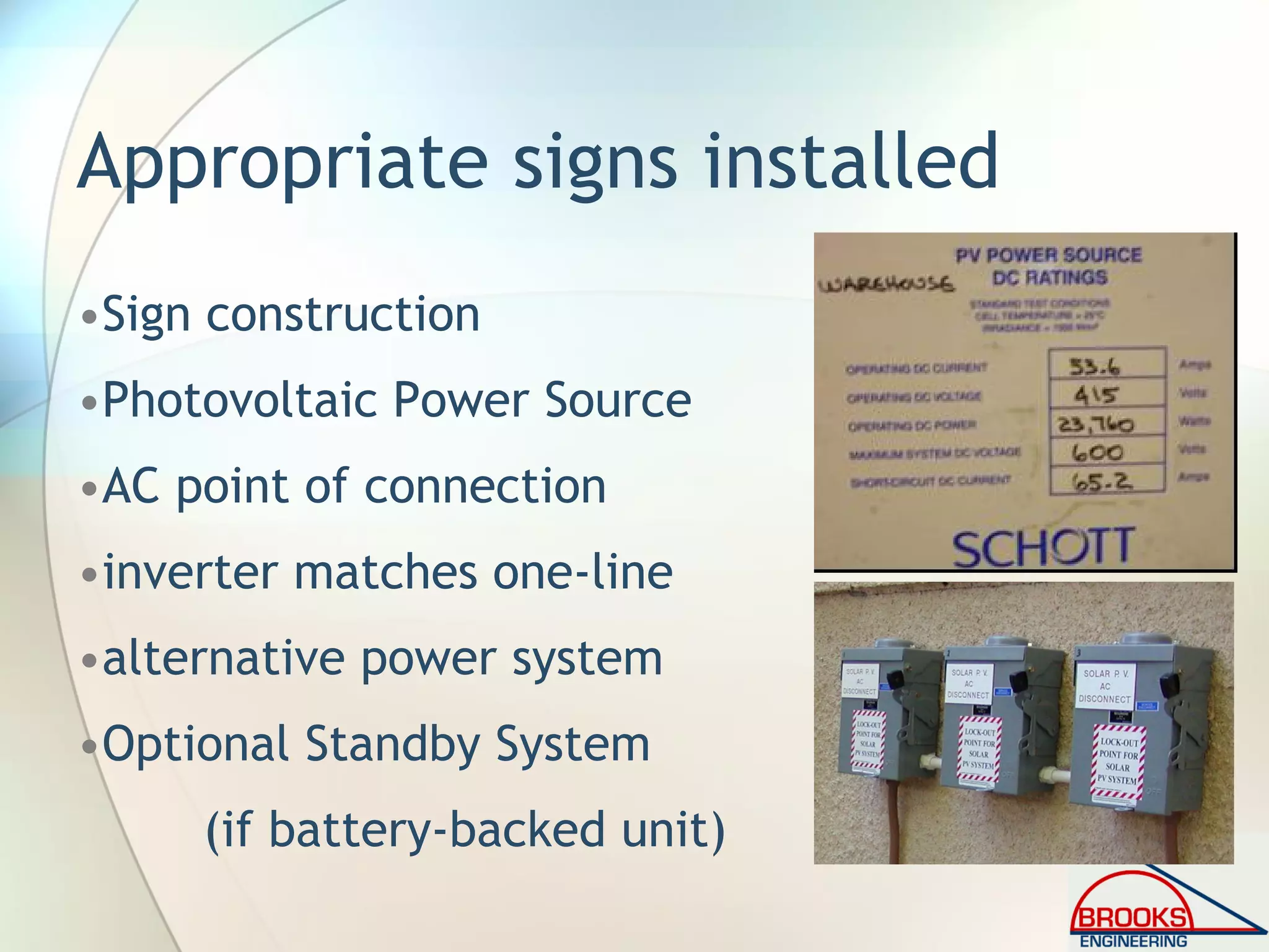
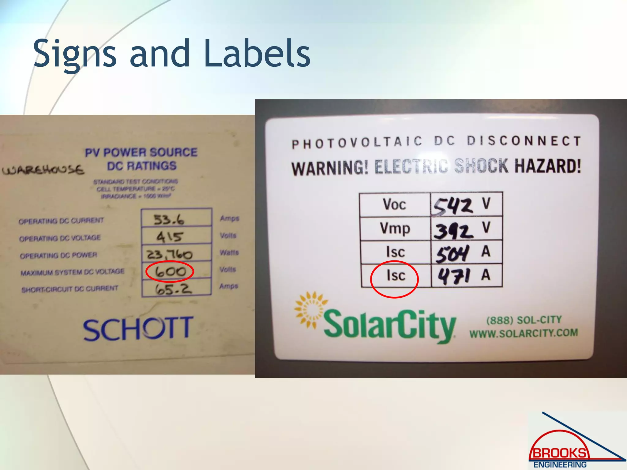
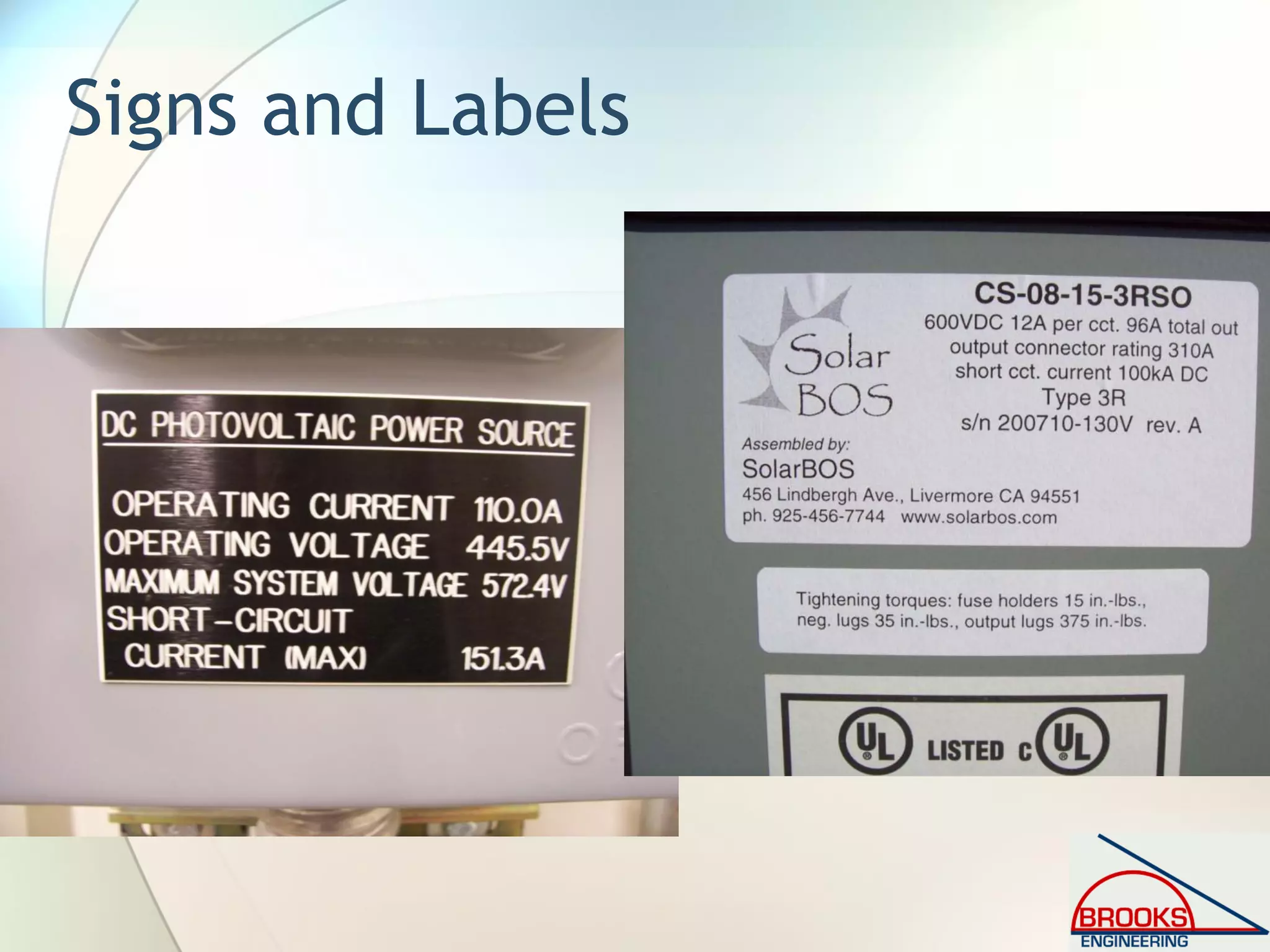
![690.53 Marking: DC PV Power Source[2008 NEC]
• (1) Rated maximum power-point current
− Imp x number of series strings
• (2) Rated maximum power-point voltage
− Vmp x number of modules in series
• (3) Maximum system voltage
− FPN to (3): See 690.7(A) for maximum photovoltaic
system voltage.
• (4) Short-circuit current
− FPN to (4): See 690.8(A) for calculation of maximum
circuit current.
• (5) Maximum rated output current of the
charge controller (if installed)](https://image.slidesharecdn.com/inspectingpvsystemsforcodecompliance-130831084458-phpapp01/75/Inspecting-Photovoltaic-PV-Systems-for-Code-Compliance-102-2048.jpg)
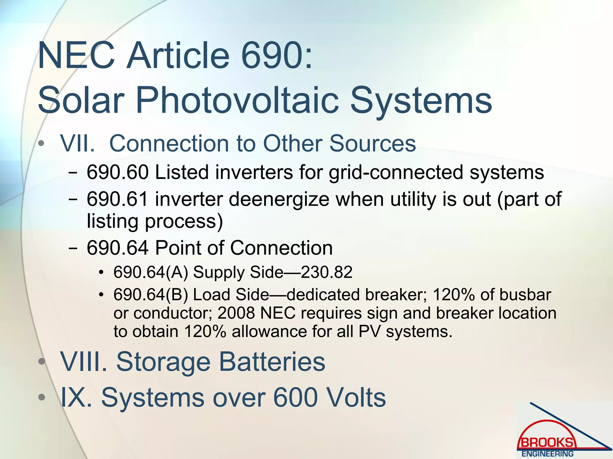
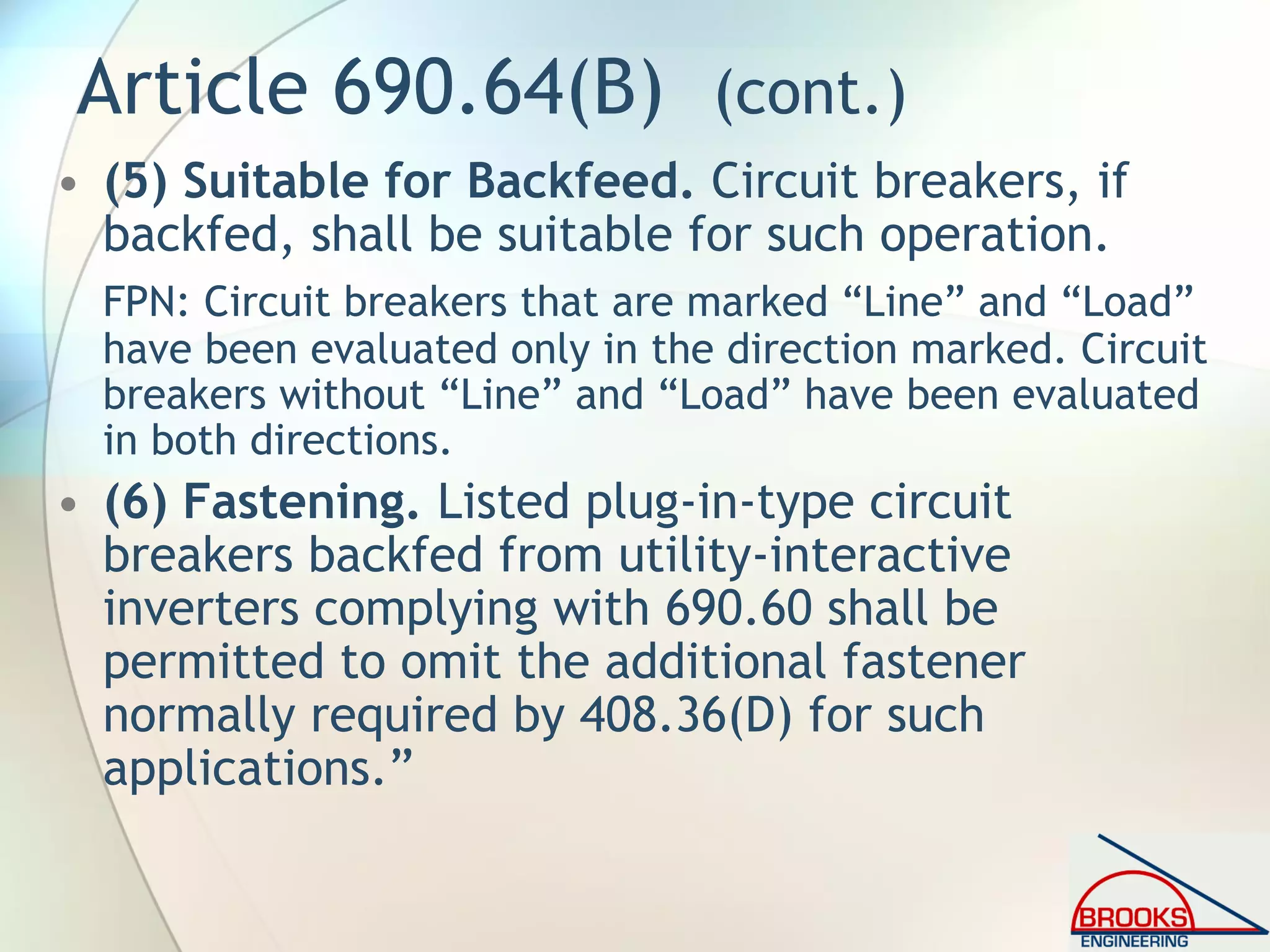
![Article 690.64 (B)(5) [2005 NEC]
• Clarification on not requiring individual clamping of
circuit breakers for 690.60 (utility-interactive)
inverters. Many inspectors will require clamps because
they are not familiar with PV systems.
• “Circuit breakers, if backfed, shall be identified for
such operation. Dedicated circuit breakers backfed
from listed utility-interactive inverters complying with
690.60 shall not be required to be individually
clamped to the panelboard bus bars. A front panel
shall clamp all circuit breakers to the panelboard bus
bars. Main circuit breakers connected directly to
energized feeders shall also be individually clamped.”](https://image.slidesharecdn.com/inspectingpvsystemsforcodecompliance-130831084458-phpapp01/75/Inspecting-Photovoltaic-PV-Systems-for-Code-Compliance-103-2048.jpg)


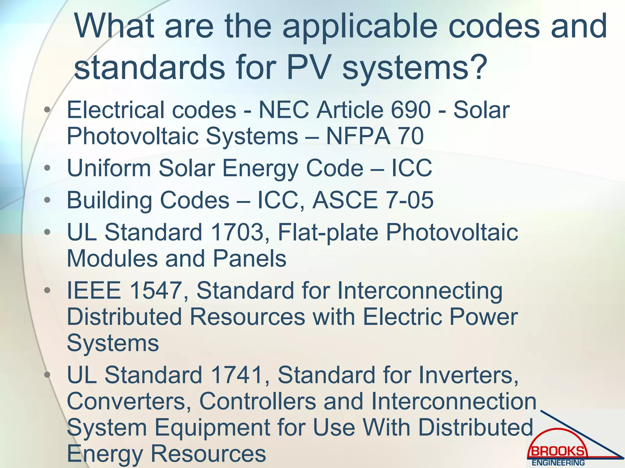
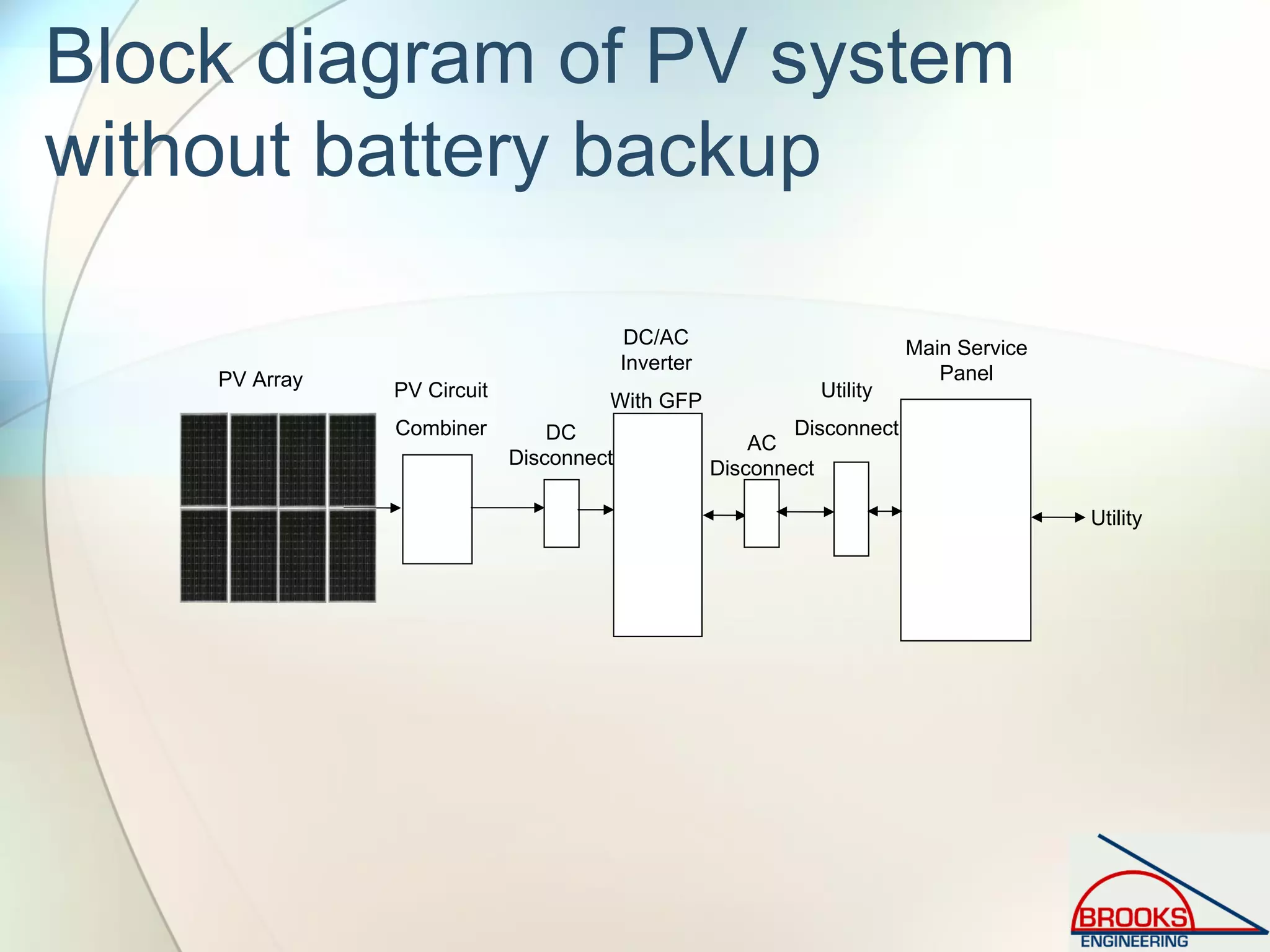
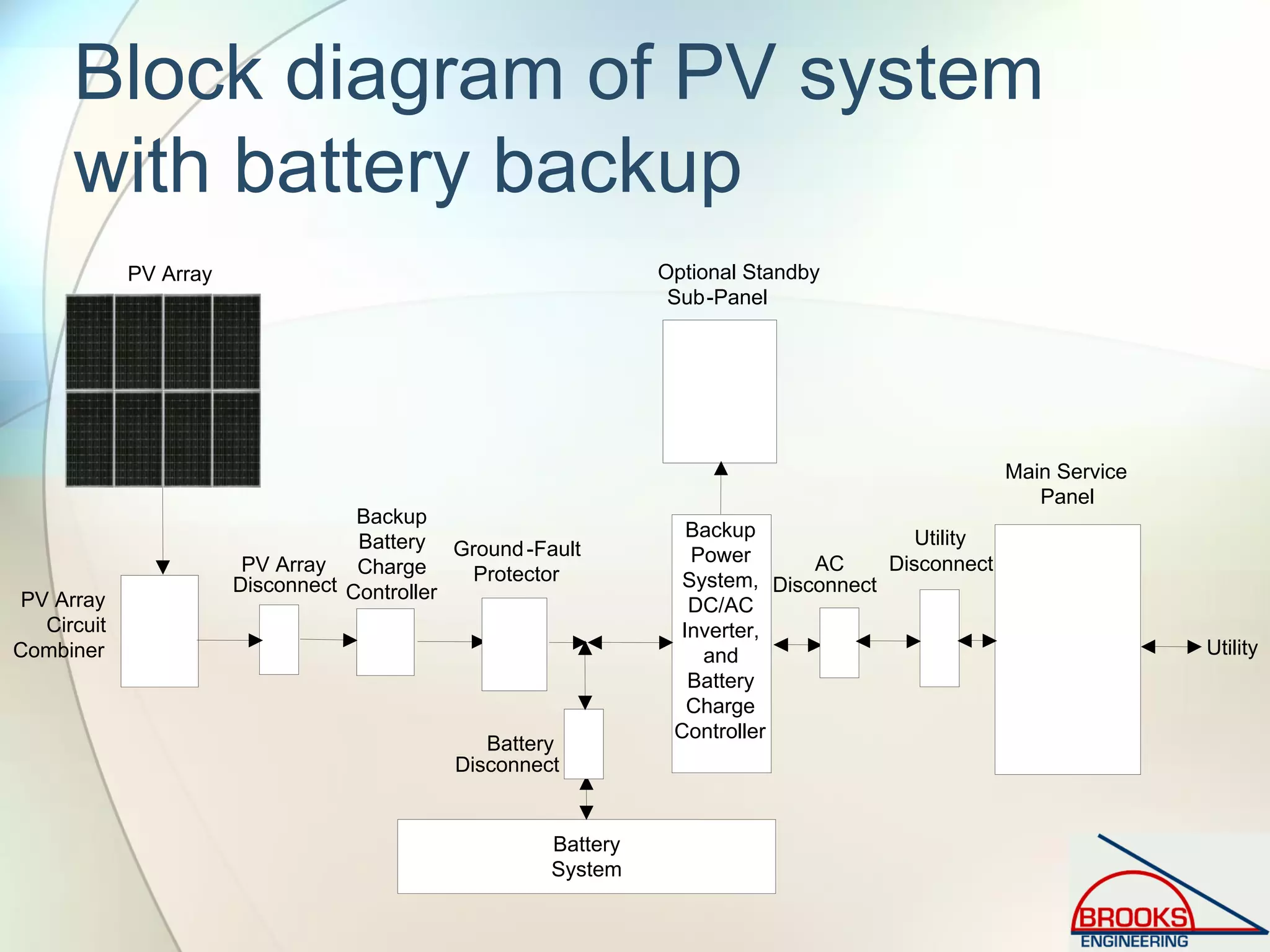
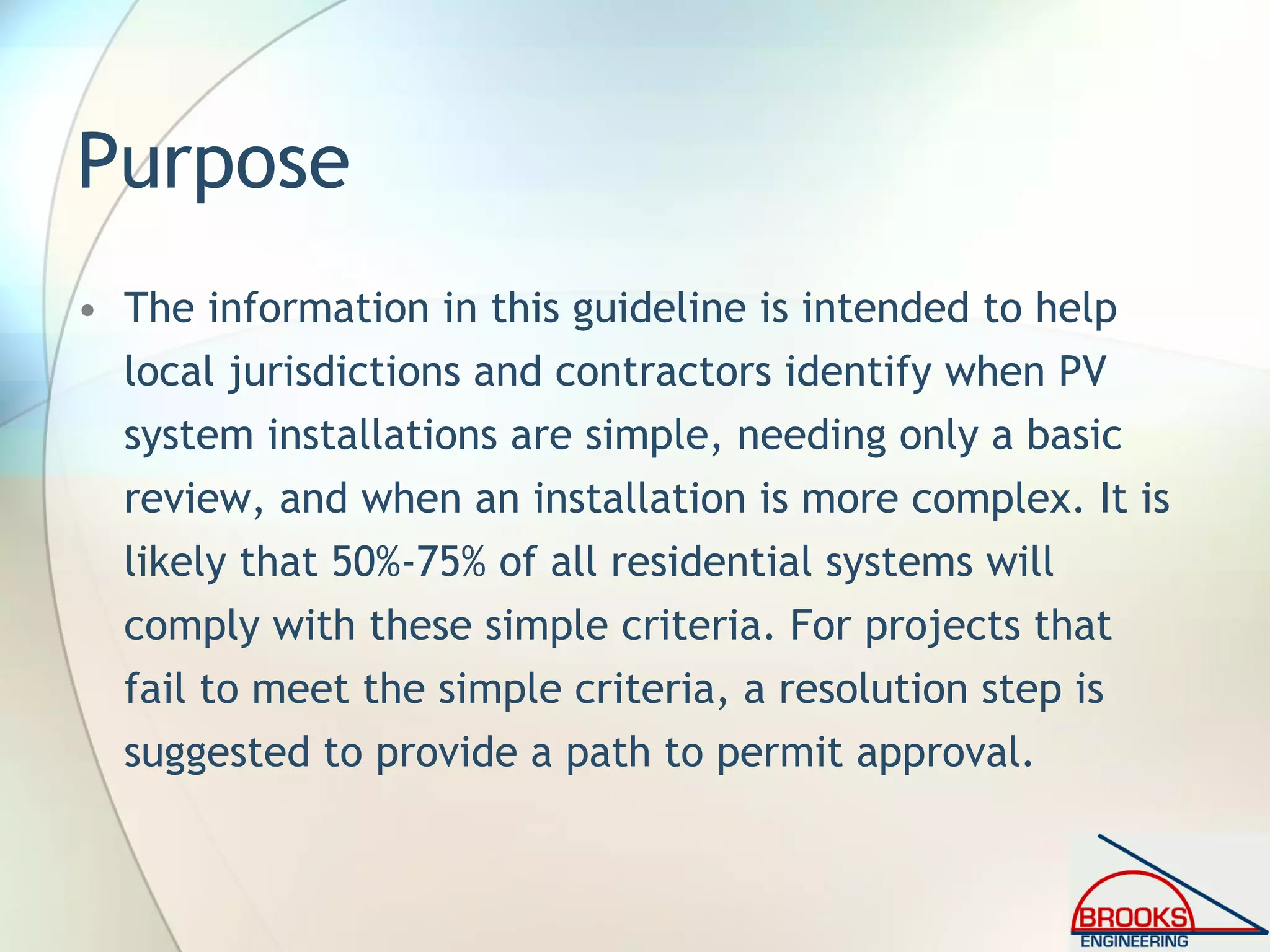
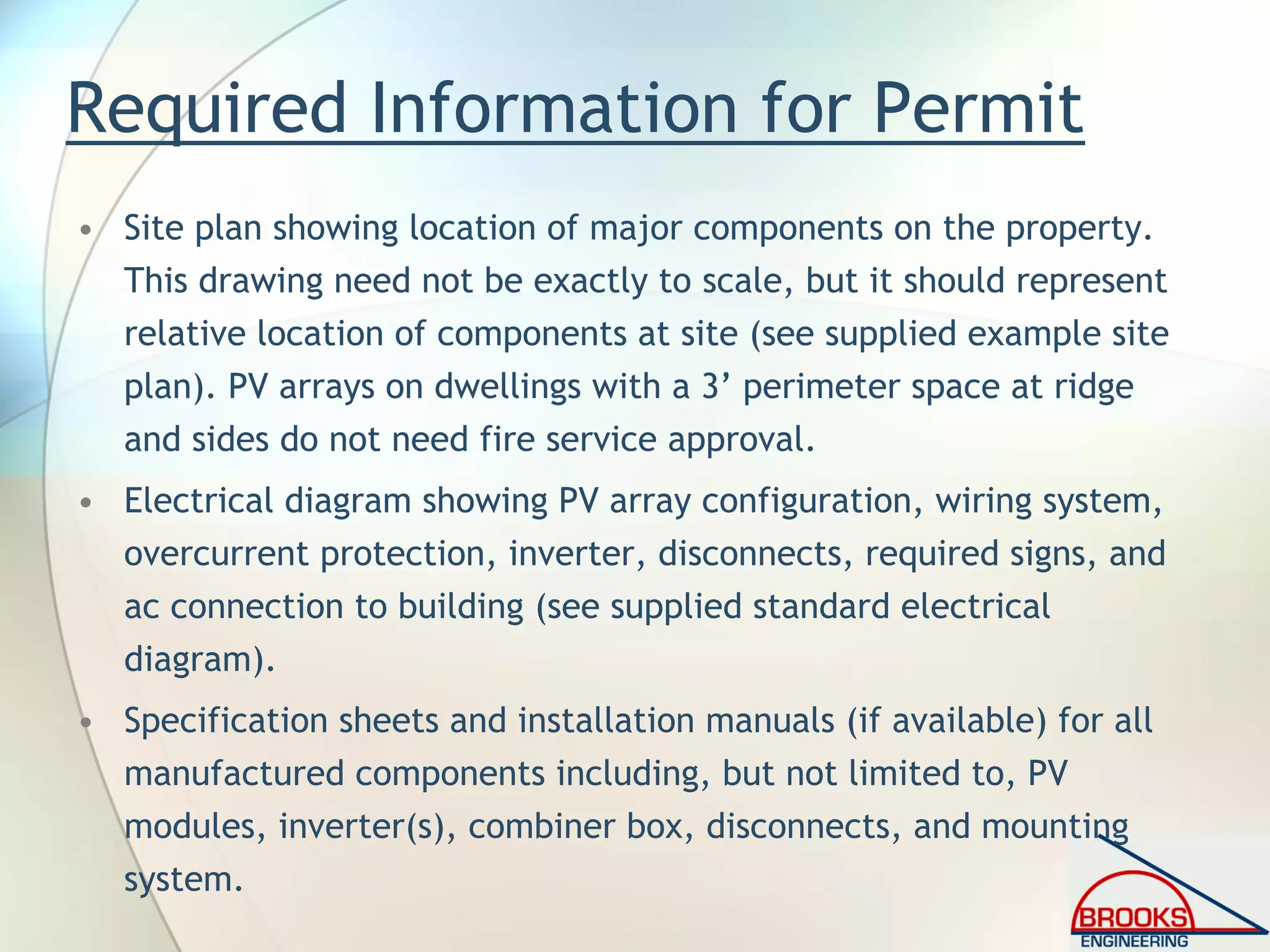
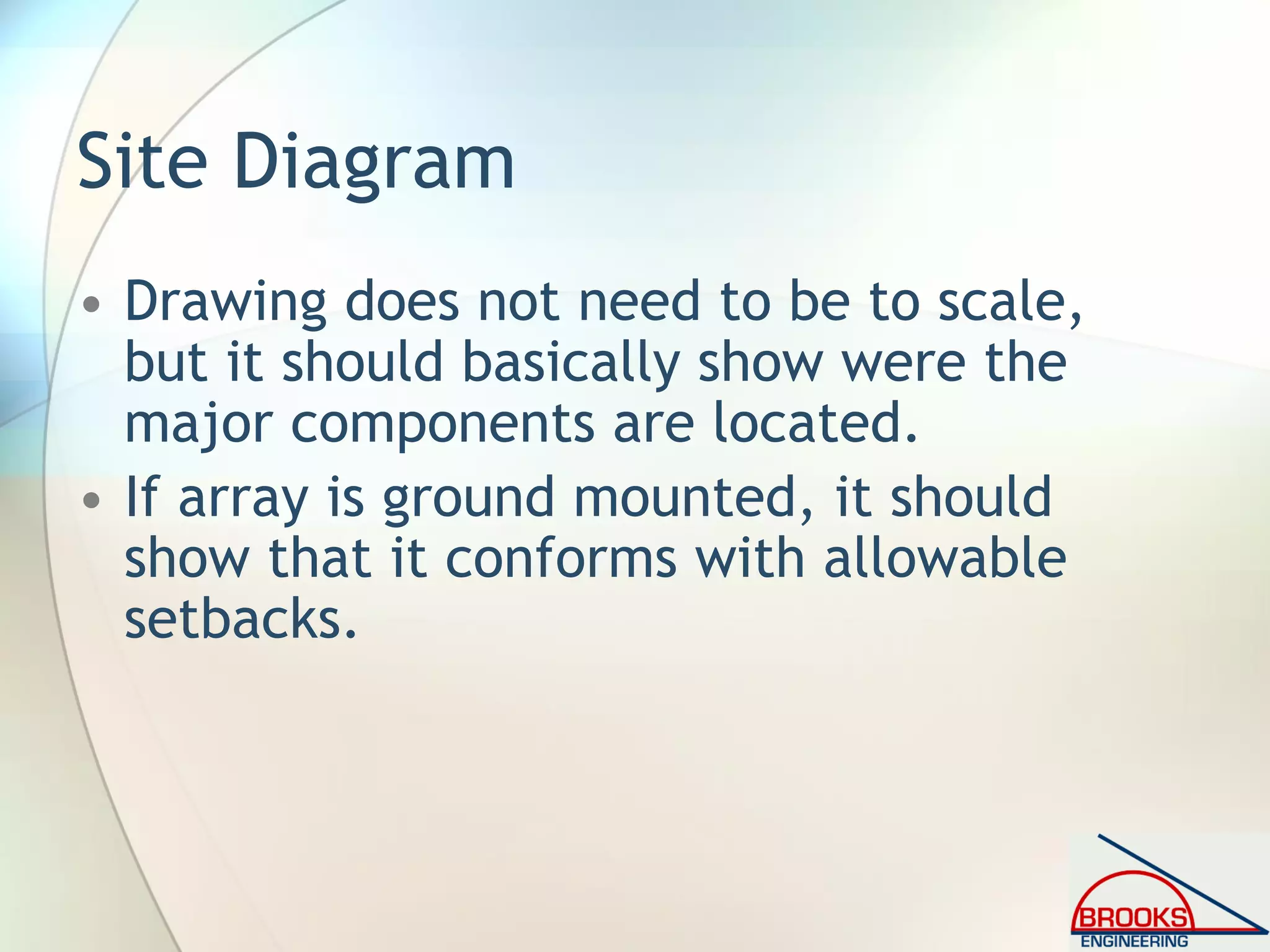
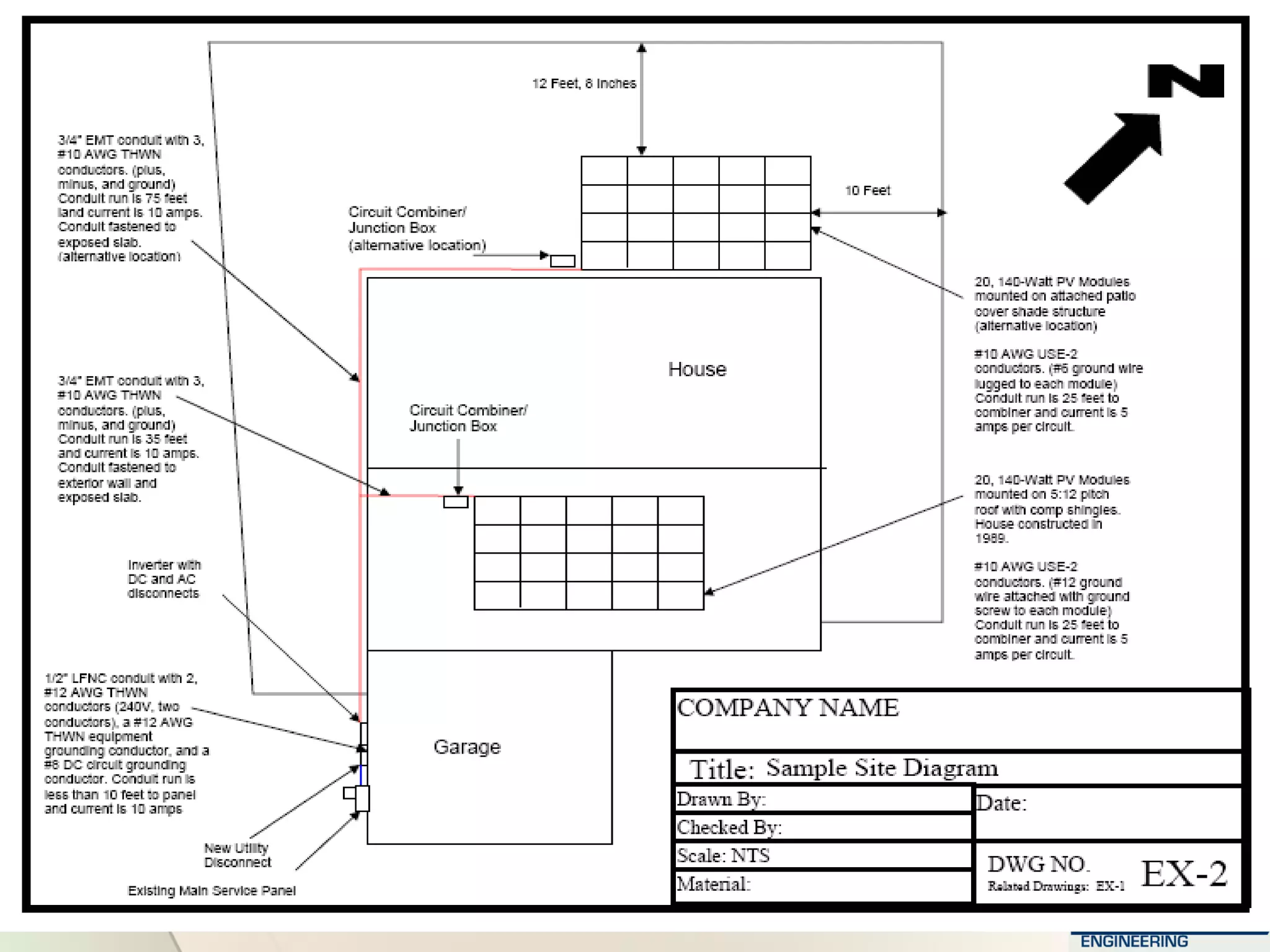
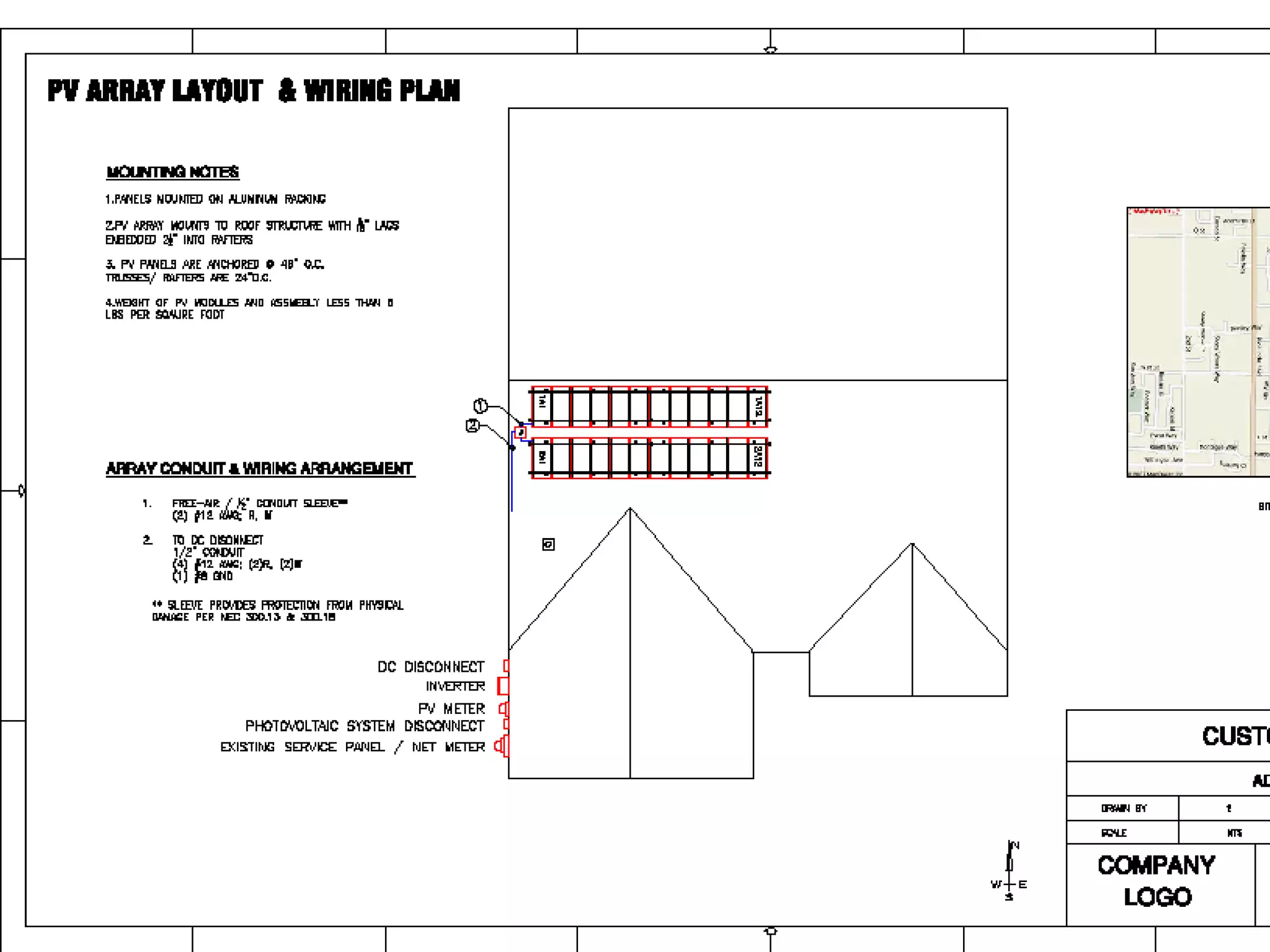
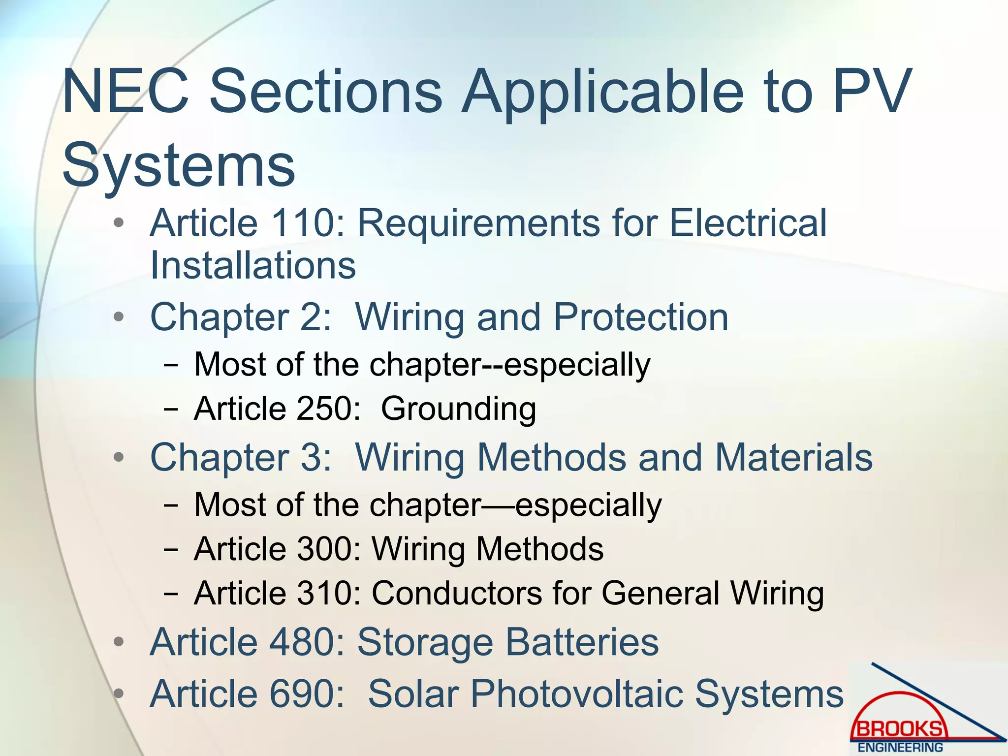
This document provides guidelines for inspecting photovoltaic (PV) systems to ensure code compliance, highlighting the need for uniformity in permit processes and safety standards. It outlines relevant codes, best practices, and the expedited permitting process for small-scale projects, designed to facilitate safe installations while raising professionalism among contractors. Additionally, it discusses the basic components and electrical design considerations critical for compliance with the National Electrical Code.


![Vibe Coding vs. Spec-Driven Development [Free Meetup]](https://cdn.slidesharecdn.com/ss_thumbnails/vibecodingvsspecdrivendevelopment-251209105622-43f455e7-thumbnail.jpg?width=640&height=640&fit=bounds)


![Coded Agents – with UiPath SDK + LangGraph [Virtual Hands-on Workshop]](https://cdn.slidesharecdn.com/ss_thumbnails/codedagentsdeck-251215155422-5497c599-thumbnail.jpg?width=640&height=640&fit=bounds)


