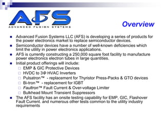
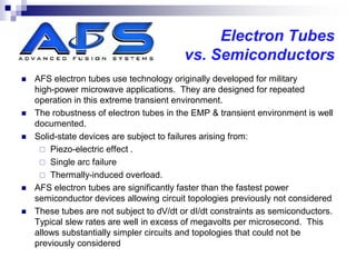
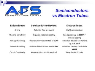
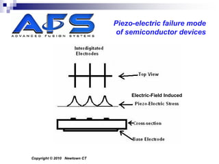
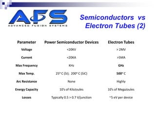
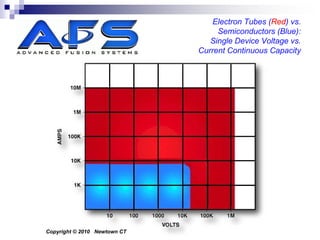
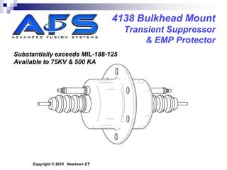
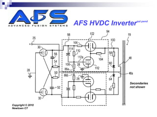
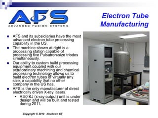
High Power Cold Cathode
           Electron Tubes for Power
           Electronics Applications

By:      Curtis Birnbach
         John Kappenman
                              Advanced Fusion Systems LLC
                                              P.O. Box 122
                                   New Rochelle, NY 10804
                                             914.772.5515
Copyright © 2010 Newtown CT
Overview
   Advanced Fusion Systems LLC (AFS) is developing a series of products for
    the power electronics market to replace semiconductor devices.
   Semiconductor devices have a number of well-known deficiencies which
    limit the utility in power electronics applications.
   AFS is currently constructing a 250,000 square foot facility to manufacture
    power electronics electron tubes in large quantities.
   Initial product offerings will include:
       EMP & GIC Protective Devices
       HVDC to 3Φ HVAC Inverters
       Pulsatron™ - replacement for Thyristor Press-Packs & GTO devices
       Bi-tron™ - replacement for IGBT
       Faultron™ Fault Current & Over-voltage Limiter
       Bulkhead Mount Transient Suppressors
   The AFS facility has an onsite testing capability for EMP, GIC, Flashover
    Fault Current. and numerous other tests common to the utility industry
    requirements
Most Powerful Cathode
   The AFS cathode is the most powerful reliable cathode known (to
    the best of our knowledge).
   It has been measured at Brookhaven National Laboratory as
    producing 81,000 Amps/cm2 in the pulse mode. It produces
    500 Amps/cm2 in the continuous mode.
   Cathodes of this type have been operated for years without
    noticeable degradation.
   This cathode technology appears in most AFS electron tube
    products.
Field Emission
                               Cold Cathode
                                    I-V Curve


Copyright © 2010 Newtown CT
COMPARISON OF
  SEMICONDUCTORS AND
ELECTRON TUBES IN POWER
ELECTRONICS APPLICATIONS
Electron Tubes
                                          vs. Semiconductors
   AFS electron tubes use technology originally developed for military
    high-power microwave applications. They are designed for repeated
    operation in this extreme transient environment.
   The robustness of electron tubes in the EMP & transient environment is well
    documented.
   Solid-state devices are subject to failures arising from:
      Piezo-electric effect .
      Single arc failure
      Thermally-induced overload.
   AFS electron tubes are significantly faster than the fastest power
    semiconductor devices allowing circuit topologies previously not considered
   These tubes are not subject to dV/dt or dI/dt constraints as semiconductors.
    Typical slew rates are well in excess of megavolts per microsecond. This
    allows substantially simpler circuits and topologies that could not be
    previously considered
Semiconductors
                                                  vs Electron Tubes

 Failure Mode           Semiconductor Devices                   Electron Tubes
      Arcing               Fail after first arc event           Highly arc resistant

Thermal Sensitivity      Requires elaborate cooling          Can operate up to 1000° F
                                                                  without cooling
 Voltage Handling     Individual devices limited to 20KV   Individual devices can handle
                                                                   up to 1.2MV
Current Handling      Individual devices can handle 8KA    Individual Devices can handle
                                                                       >1MA
Circuit Complexity     Very complex circuits required           Very simple circuits
Piezo-electric failure mode
                              of semiconductor devices


                                   Electric-Field Induced


Copyright © 2010 Newtown CT
Semiconductors vs
                                           Electron Tubes (2)

 Parameter        Power Semiconductor Devices         Electron Tubes
   Voltage                      <20KV                      > 2MV

   Current                      <20KA                       >5MA

Max Frequency                     KHz                        GHz

  Max Temp.             25ᵅ C (Si); 200ᵅ C (SiC)           500ᵅ C

Arc Resistance                   None                       Highly

Energy Capacity            10’s of KiloJoules         10’s of MegaJoules

    Losses           Typically 0.5 > 0.7 V/junction    ~5 eV per device
Electron Tubes (Red) vs.
                                   Semiconductors (Blue):
                                 Single Device Voltage vs.
                              Current Continuous Capacity


Copyright © 2010 Newtown CT
Semiconductors vs
                                                         Electron Tubes (3)
   AFS Cold Cathode Field Emission electron tubes can replace
    semiconductors in virtually every circuit configuration.
   These tubes have both turn-on and turn-off modes.
   AFS electron tubes require very little cooling due to their high
    operating temperature rating due to higher efficiency and refractory
    construction.
      Cooling not required below 1000 F operating temperature.
      No fall off in performance below maximum operating temperature
   These tubes have orders of higher energy handling capacity due to
    their refractory construction.
   Voltage and Current Limiter configurations available in all voltages
    and currents, AC & DC.

         The contents of this document are CONFIDENTIAL CORPORATE INFORMATION and may not be
         disclosed, duplicated or released without prior written consent of Advanced Fusion Systems LLC.©
Thermal efficiency
                               of power devices


Copyright © 2010 Newtown CT
DEVICES
PULSATRON™
3275 Pulsatron™

   The Pulsatron™ is a high
    vacuum, cold-cathode triode
    electron tube. It is designed for
    high-speed, high-power
    operation
   Specifications:
      DC to 3GHz
      500KV Max
      250 KA Max
                                                ^ Pulsatrons
      100 picosecond risetime
                                                  (Block 3)
      10 μSec pulse width
      > 500 KHz pulse mode
      CW Mode
                                                 < High Speed
   Compact: 5” 12”, 5lbs                         Class A Amp


         Copyright © 2010 Newtown CT
1 GHz Power Oscillator


Y-axis =
 + 60dB
                                               Tr = 985 ps


    Copyright © 2010 Newtown CT
Bi-tron™ pat pending
Bi-tron™
   The Bi-tron™ is a bi-directional tetrode electrode designed for sub-
    nanosecond AC switching operations.
   The Bi-tron™ incorporates the AFS travelling-wave electron gun
    technology has risetimes in the 100 picosecond range and current-
    handling ability to hundreds of KiloAmps or more.
   The Bi-tron™ is designed to operate in the EMP environment and is
    capable of handling repeated pulses at multi-kilohertz rep rates, a
    situation not encountered in EMP/GIC protection, but one which the
    tube is capable of reliable operation.
   Bi-directional operation is enabled by a unique proprietary tube
    element called the “Cathanode™”. This element is capable of
    operating as either a cathode or anode depending on the polarity of
    the applied voltage.
4275 Bi-tron™

   The Bi-tron™ is a high vacuum, cold-cathode tetrode electron tube. It is
    designed for bi-directional (or bipolar) high-speed, high-power shunt operation
   Specifications:
      1200KVAC Max
      750 KA Max
   Size varies with voltage. Units below 35KVAC are 5 inches in diameter and
    12” long. Units for 1250 KVAC operation are approximately 6 feet in diameter.
   Units under 2 feet in diameter have external control circuits. Larger units have
    the control circuitry mounted internally.
   All systems have dual vacuum pumping systems. The active system is
    powered by the line it is attached to. There is also a chemical getter pump
    capable of maintaining operational vacuum without external power.
   All systems provide an external control signal to trip external protective
    systems.
   All systems are self-resetting and are capable of withstanding and protecting
    multiple events in rapid succession.
   These devices also protect against lightning of all voltages.
4275 Bi-tron™


                               Some structures omitted for clarity


Copyright © 2010 Newtown CT
4138 Bi-tron™
   The 4138 is a patent-pending bulkhead mounted version
    of the Bi-tron designed for series insertion in transient
    suppressor applications.
   It retains the electrical characteristics of the 4275, but is
    packaged in a housing optimized for bulkhead mounting
    as a shielded protective feedthrough.
   The design exceeds the Mil188-125 specification
   Available to 75KV and 250 KA
   This tube is designed for transient suppressor and EMP
    protection
4138 Bi-tron™
                              Series Configuration


Copyright © 2010 Newtown CT
APPLICATIONS
Geomagnetically-Induced
Current Protection Systems
GIC Protection

   AFS offers Kappenman-method Neutral Blocking
    devices and systems
   AFS Offers active GIC current limiters
   This topics was discussed in yesterdays session
Kappenman GIC
                              Neutral Blocking Device


Copyright © 2010 Newtown CT
4275 Bi-tron™
                                              35 KV
                                             500 KA


5” dia. x 12” L                    Some details have been
                                   omitted for clarity
12 Lbs

  Copyright © 2010 Newtown CT
Transient Suppressor
4138 Bulkhead Mount
                                      Transient Suppressor
                                           & EMP Protector
Substantially exceeds MIL-188-125
Available to 75KV & 500 KA


      Copyright © 2010 Newtown CT
HVDC Inverter
pat pend
                   AFS HVDC Inverter


                                  Secondaries
                                  not shown


Copyright © 2010
Newtown CT
Current Regulation
DC Current
                           pat pend
                   Regulator


Copyright © 2010
Newtown CT
Combined Over-voltage & Over-current Limiter


Copyright © 2010
Newtown CT
™patpend
                              Vacuum Integrated Circuit
Combined Over-voltage & Over-current Limiter


Copyright © 2010 Newtown CT
SUPER MOV
REPLACEMENT
Super MOV Replacement
                              (3-Phase; Artist Concept)


Copyright © 2010 Newtown CT
EPS™ (EMP
Protection Systems)
AFS EPS™
                                                    EMP Protection
   AFS has developed the EPS™ series EMP Protection device and system
    for grid-level protection.
   This series of devices implement AFS’ patent-pending Field Collapse™
    technique, where the magnetic field in the core winding is instantly shorted
    out, collapsing the magnetic field to prevent damage
   The individual device is a stand-alone element that connects directly to the
    transformer or generator to be protected.
   These devices also provide GIC protection.
   The EPS™ turns on in less than 100 picoseconds and safely conducts the
    EMP energy to ground.
   Overall system recovery time is measured in hours or days as opposed to
    years.
       Recovery period decreases as level of grid protection increases.
™ pat pend
                                                   AFS EPS
                                                   EMP Protector
Each phase is protected by a device like this:        >>>
Each EPS™ consists of a dielectric vacuum. enclosure, a
ground conductor, and specialized internal structures.
These devices implement the Field-Collapse™ protocol
Detection and operation are autonomous.
The EPS™ has internal vacuum pumps to ensure
constant availability.
The EPS™ provides a hardened data output containing
information on the EPS™ status and EMP Event alert.
These units are networked using hardened technology to
provide system operators an alert of an event or system
failure.
The units are available from 480V to 800KV.
Cost of EMP Protection offset by anticipated reduction in
insurance costs


                                                             Copyright © 2010 Newtown CT
NNEMP
   Most discussions on EMP focus on nuclear-induced EMP.
    However, there are non-nuclear EMP sources that are capable of
    substantially higher electric fields which present a significant threat.
   Several of these extremely powerful non-nuclear sources have been
    demonstrated.
   Some have been certified by the USG as having field strengths in
    excess of 250/KV/m
   Some of these devices are portable.
   This presents a threat which exceeds the levels of protection
    afforded by systems just in compliance with MIL-188-125.
   These threats are relatively inexpensive and lend themselves to
    multiple simultaneous attack scenarios
ABOUT
ADVANCED FUSION SYSTEMS LLC
AFS Overview
   Advanced Fusion Systems LLC (AFS) was formed in 2008 to develop and
    exploit patent-pending and proprietary technologies to produce a series of
    related products:
      E2P Extraordinary Electromagnetic Pulse (EMP) Protection systems
      GIC Protection Systems
      Faultron™ Fault Current & Over-Voltage Limiters
      FXI Environmental Remediation Systems
      Pulse Power-Based Systems
      Advanced Electron Tubes
   All technologies are US and International Patents-Pending
   AFS has acquired the assets of Hudson Research Inc which is now a
    subsidiary.
   AFS has acquired the assets of Thryonics Inc which is now a subsidiary.
   AFS has acquired a 250,000 sq. foot facility in Connecticut
   AFS is a privately-held Delaware corporation.
AFS New Facility

                                                              Expanded    ↑↑
                                                              facility


                                                              Satellite view of
                                                              << existing facility


Newtown, CT. 250,000 ft2. Radiation Lab; EMP Test to 1MV AC/DC @ 250KV/M
Advanced
                                                      Manufacturing
                                                        Capabilities
   CNC Machining: 7-axis, 5-axis, & 4-axis systems (micron tolerances)
   Electron Tube Processing
   Electrochemical Processing
      Electropolishing
      Electro-chemical Machining
   Vacuum-grade Reinforced Ceramics
   Graphite Fabrication
   Glass Fabrication
   Ultra-High-Speed Electronics
   Optical Fabrication
   Thin-Film Processing; Ion Plating
   Plasma Processing
   40 MW power feed to fully shielded test facility
      Radiation Lab: 1 MeV; 100’L x 34’W x 20’H; 3 foot thick concrete walls
      EMP Test Cells: Electric & Magnetic Shielding ; 250KV/M sources)
         (2) @ 135’ x 50’ x 50’; (1) @ 80’ x 40’ x 22’ (also RF anechoic)
EMP Test Facility

   It is essential that all devices be tested under realistic conditions, but there are no
    EMP test facilities capable of on-load testing devices up to 1 million volts (that we are
    aware of).
   As part of our commitment to the EMP protection arena, AFS is constructing a world-
    class EMP test facility.
   This facility will be capable of testing devices at line voltages up to 1.2 million VAC or
    VDC, under load conditions of up to 10MW, and in a sub-100 picosecond risetime
    pulsed electric field environment of >250 KV/m..
   While the facility is primarily for AFS production use, AFS will make it available to
    outside users if the USG certifies the facility.
   This facility will test in excess of the Mil-188-125 standard so as to provide realistic
    IEMP conditions.
   This facility can successfully create SGEMP pulses
   This facility also does fault-current testing, flashover, and other tests.
Advanced
Manufacturing
 Capabilities
Advanced
                                        Manufacturing
   This is a photo of our
    large CNC machine.
   It is a fully computerized
    7-axis machining center.
   Machining tolerance is
    0.00005” over 25 feet
   It can handle parts up to
    7 feet in diameter, up to
    25 feet long, weighing
    over 35 tons
   This machine itself is 65
    feet long and weighs
    85,000 pounds
   A sister machine has
    been acquired for deep
    boring to 25 foot depth


          Copyright © 2010 Newtown CT
Electron Tube
                                              Manufacturing
   AFS and its subsidiaries have the most
    advanced electron tube processing
    capability in the US.
   The machine shown at right is a
    processing station capable of
    processing five Pulsatron-size triodes
    simultaneously.
   Our ability to custom build processing
    equipment coupled with our
    extraordinary machining and chemical
    processing technology allows us to
    build electron tubes of virtually any
    size, a capability that no other
    company in the US has.
   AFS is the only manufacturer of direct
    electrically driven X-ray lasers.
     • A 50 KJ (x-ray output) unit is under
        design and will be built and tested
        during 2011.

         Copyright © 2010 Newtown CT
Advanced
                                   Manufacturing (2)

   All critical components are manufactured in-house.
   This manufacturing is supported by a world-class Quality
    Assurance systems to ensure “Zero-Defects.”
   We use 100% inspection and test for all products.
   Each EPS & GIC protection device is tested in our
    EMP test facility and certified under realistic load
    conditions to guarantee operability. Customers are
    welcome to witness this certification procedure.
   Each EPS unit comes with performance documentation.
Thin Film Coating


Copyright © 2010
Newtown CT


             The contents of this document are CONFIDENTIAL CORPORATE INFORMATION and may not be
             disclosed, duplicated or released without prior written consent of Advanced Fusion Systems LLC.©
Contact


     Advanced Fusion Systems LLC.
     P.O. Box 3247
     Newtown CT, 06470
Curtis Birnbach           John Kappenman
P.O. Box 122              301 W. First St, Suite 615
New Rochelle, NY 10804    Duluth MN. 55802
914.772.5515              218.727.2666
cbirnbach@advfusion.com   jkappenma@aol.com

Electron Tube Afs Epri R5

  • 1.
    High Power ColdCathode Electron Tubes for Power Electronics Applications By: Curtis Birnbach John Kappenman Advanced Fusion Systems LLC P.O. Box 122 New Rochelle, NY 10804 914.772.5515 Copyright © 2010 Newtown CT
  • 2.
    Overview  Advanced Fusion Systems LLC (AFS) is developing a series of products for the power electronics market to replace semiconductor devices.  Semiconductor devices have a number of well-known deficiencies which limit the utility in power electronics applications.  AFS is currently constructing a 250,000 square foot facility to manufacture power electronics electron tubes in large quantities.  Initial product offerings will include:  EMP & GIC Protective Devices  HVDC to 3Φ HVAC Inverters  Pulsatron™ - replacement for Thyristor Press-Packs & GTO devices  Bi-tron™ - replacement for IGBT  Faultron™ Fault Current & Over-voltage Limiter  Bulkhead Mount Transient Suppressors  The AFS facility has an onsite testing capability for EMP, GIC, Flashover Fault Current. and numerous other tests common to the utility industry requirements
  • 3.
    Most Powerful Cathode  The AFS cathode is the most powerful reliable cathode known (to the best of our knowledge).  It has been measured at Brookhaven National Laboratory as producing 81,000 Amps/cm2 in the pulse mode. It produces 500 Amps/cm2 in the continuous mode.  Cathodes of this type have been operated for years without noticeable degradation.  This cathode technology appears in most AFS electron tube products.
  • 4.
    Field Emission Cold Cathode I-V Curve Copyright © 2010 Newtown CT
  • 5.
    COMPARISON OF SEMICONDUCTORS AND ELECTRON TUBES IN POWER ELECTRONICS APPLICATIONS
  • 6.
    Electron Tubes vs. Semiconductors  AFS electron tubes use technology originally developed for military high-power microwave applications. They are designed for repeated operation in this extreme transient environment.  The robustness of electron tubes in the EMP & transient environment is well documented.  Solid-state devices are subject to failures arising from:  Piezo-electric effect .  Single arc failure  Thermally-induced overload.  AFS electron tubes are significantly faster than the fastest power semiconductor devices allowing circuit topologies previously not considered  These tubes are not subject to dV/dt or dI/dt constraints as semiconductors. Typical slew rates are well in excess of megavolts per microsecond. This allows substantially simpler circuits and topologies that could not be previously considered
  • 7.
    Semiconductors vs Electron Tubes Failure Mode Semiconductor Devices Electron Tubes Arcing Fail after first arc event Highly arc resistant Thermal Sensitivity Requires elaborate cooling Can operate up to 1000° F without cooling Voltage Handling Individual devices limited to 20KV Individual devices can handle up to 1.2MV Current Handling Individual devices can handle 8KA Individual Devices can handle >1MA Circuit Complexity Very complex circuits required Very simple circuits
  • 8.
    Piezo-electric failure mode of semiconductor devices Electric-Field Induced Copyright © 2010 Newtown CT
  • 9.
    Semiconductors vs Electron Tubes (2) Parameter Power Semiconductor Devices Electron Tubes Voltage <20KV > 2MV Current <20KA >5MA Max Frequency KHz GHz Max Temp. 25ᵅ C (Si); 200ᵅ C (SiC) 500ᵅ C Arc Resistance None Highly Energy Capacity 10’s of KiloJoules 10’s of MegaJoules Losses Typically 0.5 > 0.7 V/junction ~5 eV per device
  • 10.
    Electron Tubes (Red)vs. Semiconductors (Blue): Single Device Voltage vs. Current Continuous Capacity Copyright © 2010 Newtown CT
  • 11.
    Semiconductors vs Electron Tubes (3)  AFS Cold Cathode Field Emission electron tubes can replace semiconductors in virtually every circuit configuration.  These tubes have both turn-on and turn-off modes.  AFS electron tubes require very little cooling due to their high operating temperature rating due to higher efficiency and refractory construction.  Cooling not required below 1000 F operating temperature.  No fall off in performance below maximum operating temperature  These tubes have orders of higher energy handling capacity due to their refractory construction.  Voltage and Current Limiter configurations available in all voltages and currents, AC & DC. The contents of this document are CONFIDENTIAL CORPORATE INFORMATION and may not be disclosed, duplicated or released without prior written consent of Advanced Fusion Systems LLC.©
  • 12.
    Thermal efficiency of power devices Copyright © 2010 Newtown CT
  • 13.
  • 14.
  • 15.
    3275 Pulsatron™  The Pulsatron™ is a high vacuum, cold-cathode triode electron tube. It is designed for high-speed, high-power operation  Specifications:  DC to 3GHz  500KV Max  250 KA Max ^ Pulsatrons  100 picosecond risetime (Block 3)  10 μSec pulse width  > 500 KHz pulse mode  CW Mode < High Speed  Compact: 5” 12”, 5lbs Class A Amp Copyright © 2010 Newtown CT
  • 16.
    1 GHz PowerOscillator Y-axis = + 60dB Tr = 985 ps Copyright © 2010 Newtown CT
  • 17.
  • 18.
    Bi-tron™  The Bi-tron™ is a bi-directional tetrode electrode designed for sub- nanosecond AC switching operations.  The Bi-tron™ incorporates the AFS travelling-wave electron gun technology has risetimes in the 100 picosecond range and current- handling ability to hundreds of KiloAmps or more.  The Bi-tron™ is designed to operate in the EMP environment and is capable of handling repeated pulses at multi-kilohertz rep rates, a situation not encountered in EMP/GIC protection, but one which the tube is capable of reliable operation.  Bi-directional operation is enabled by a unique proprietary tube element called the “Cathanode™”. This element is capable of operating as either a cathode or anode depending on the polarity of the applied voltage.
  • 19.
    4275 Bi-tron™  The Bi-tron™ is a high vacuum, cold-cathode tetrode electron tube. It is designed for bi-directional (or bipolar) high-speed, high-power shunt operation  Specifications:  1200KVAC Max  750 KA Max  Size varies with voltage. Units below 35KVAC are 5 inches in diameter and 12” long. Units for 1250 KVAC operation are approximately 6 feet in diameter.  Units under 2 feet in diameter have external control circuits. Larger units have the control circuitry mounted internally.  All systems have dual vacuum pumping systems. The active system is powered by the line it is attached to. There is also a chemical getter pump capable of maintaining operational vacuum without external power.  All systems provide an external control signal to trip external protective systems.  All systems are self-resetting and are capable of withstanding and protecting multiple events in rapid succession.  These devices also protect against lightning of all voltages.
  • 20.
    4275 Bi-tron™ Some structures omitted for clarity Copyright © 2010 Newtown CT
  • 21.
    4138 Bi-tron™  The 4138 is a patent-pending bulkhead mounted version of the Bi-tron designed for series insertion in transient suppressor applications.  It retains the electrical characteristics of the 4275, but is packaged in a housing optimized for bulkhead mounting as a shielded protective feedthrough.  The design exceeds the Mil188-125 specification  Available to 75KV and 250 KA  This tube is designed for transient suppressor and EMP protection
  • 22.
    4138 Bi-tron™ Series Configuration Copyright © 2010 Newtown CT
  • 23.
  • 24.
  • 25.
    GIC Protection  AFS offers Kappenman-method Neutral Blocking devices and systems  AFS Offers active GIC current limiters  This topics was discussed in yesterdays session
  • 26.
    Kappenman GIC Neutral Blocking Device Copyright © 2010 Newtown CT
  • 27.
    4275 Bi-tron™ 35 KV 500 KA 5” dia. x 12” L Some details have been omitted for clarity 12 Lbs Copyright © 2010 Newtown CT
  • 28.
  • 29.
    4138 Bulkhead Mount Transient Suppressor & EMP Protector Substantially exceeds MIL-188-125 Available to 75KV & 500 KA Copyright © 2010 Newtown CT
  • 30.
  • 31.
    pat pend AFS HVDC Inverter Secondaries not shown Copyright © 2010 Newtown CT
  • 32.
  • 33.
    DC Current pat pend Regulator Copyright © 2010 Newtown CT
  • 34.
    Combined Over-voltage &Over-current Limiter Copyright © 2010 Newtown CT
  • 35.
    ™patpend Vacuum Integrated Circuit Combined Over-voltage & Over-current Limiter Copyright © 2010 Newtown CT
  • 36.
  • 37.
    Super MOV Replacement (3-Phase; Artist Concept) Copyright © 2010 Newtown CT
  • 38.
  • 39.
    AFS EPS™ EMP Protection  AFS has developed the EPS™ series EMP Protection device and system for grid-level protection.  This series of devices implement AFS’ patent-pending Field Collapse™ technique, where the magnetic field in the core winding is instantly shorted out, collapsing the magnetic field to prevent damage  The individual device is a stand-alone element that connects directly to the transformer or generator to be protected.  These devices also provide GIC protection.  The EPS™ turns on in less than 100 picoseconds and safely conducts the EMP energy to ground.  Overall system recovery time is measured in hours or days as opposed to years.  Recovery period decreases as level of grid protection increases.
  • 40.
    ™ pat pend AFS EPS EMP Protector Each phase is protected by a device like this: >>> Each EPS™ consists of a dielectric vacuum. enclosure, a ground conductor, and specialized internal structures. These devices implement the Field-Collapse™ protocol Detection and operation are autonomous. The EPS™ has internal vacuum pumps to ensure constant availability. The EPS™ provides a hardened data output containing information on the EPS™ status and EMP Event alert. These units are networked using hardened technology to provide system operators an alert of an event or system failure. The units are available from 480V to 800KV. Cost of EMP Protection offset by anticipated reduction in insurance costs Copyright © 2010 Newtown CT
  • 41.
    NNEMP  Most discussions on EMP focus on nuclear-induced EMP. However, there are non-nuclear EMP sources that are capable of substantially higher electric fields which present a significant threat.  Several of these extremely powerful non-nuclear sources have been demonstrated.  Some have been certified by the USG as having field strengths in excess of 250/KV/m  Some of these devices are portable.  This presents a threat which exceeds the levels of protection afforded by systems just in compliance with MIL-188-125.  These threats are relatively inexpensive and lend themselves to multiple simultaneous attack scenarios
  • 42.
  • 43.
    AFS Overview  Advanced Fusion Systems LLC (AFS) was formed in 2008 to develop and exploit patent-pending and proprietary technologies to produce a series of related products:  E2P Extraordinary Electromagnetic Pulse (EMP) Protection systems  GIC Protection Systems  Faultron™ Fault Current & Over-Voltage Limiters  FXI Environmental Remediation Systems  Pulse Power-Based Systems  Advanced Electron Tubes  All technologies are US and International Patents-Pending  AFS has acquired the assets of Hudson Research Inc which is now a subsidiary.  AFS has acquired the assets of Thryonics Inc which is now a subsidiary.  AFS has acquired a 250,000 sq. foot facility in Connecticut  AFS is a privately-held Delaware corporation.
  • 44.
    AFS New Facility Expanded ↑↑ facility Satellite view of << existing facility Newtown, CT. 250,000 ft2. Radiation Lab; EMP Test to 1MV AC/DC @ 250KV/M
  • 45.
    Advanced Manufacturing Capabilities  CNC Machining: 7-axis, 5-axis, & 4-axis systems (micron tolerances)  Electron Tube Processing  Electrochemical Processing  Electropolishing  Electro-chemical Machining  Vacuum-grade Reinforced Ceramics  Graphite Fabrication  Glass Fabrication  Ultra-High-Speed Electronics  Optical Fabrication  Thin-Film Processing; Ion Plating  Plasma Processing  40 MW power feed to fully shielded test facility  Radiation Lab: 1 MeV; 100’L x 34’W x 20’H; 3 foot thick concrete walls  EMP Test Cells: Electric & Magnetic Shielding ; 250KV/M sources) (2) @ 135’ x 50’ x 50’; (1) @ 80’ x 40’ x 22’ (also RF anechoic)
  • 46.
    EMP Test Facility  It is essential that all devices be tested under realistic conditions, but there are no EMP test facilities capable of on-load testing devices up to 1 million volts (that we are aware of).  As part of our commitment to the EMP protection arena, AFS is constructing a world- class EMP test facility.  This facility will be capable of testing devices at line voltages up to 1.2 million VAC or VDC, under load conditions of up to 10MW, and in a sub-100 picosecond risetime pulsed electric field environment of >250 KV/m..  While the facility is primarily for AFS production use, AFS will make it available to outside users if the USG certifies the facility.  This facility will test in excess of the Mil-188-125 standard so as to provide realistic IEMP conditions.  This facility can successfully create SGEMP pulses  This facility also does fault-current testing, flashover, and other tests.
  • 47.
  • 48.
    Advanced Manufacturing  This is a photo of our large CNC machine.  It is a fully computerized 7-axis machining center.  Machining tolerance is 0.00005” over 25 feet  It can handle parts up to 7 feet in diameter, up to 25 feet long, weighing over 35 tons  This machine itself is 65 feet long and weighs 85,000 pounds  A sister machine has been acquired for deep boring to 25 foot depth Copyright © 2010 Newtown CT
  • 49.
    Electron Tube Manufacturing  AFS and its subsidiaries have the most advanced electron tube processing capability in the US.  The machine shown at right is a processing station capable of processing five Pulsatron-size triodes simultaneously.  Our ability to custom build processing equipment coupled with our extraordinary machining and chemical processing technology allows us to build electron tubes of virtually any size, a capability that no other company in the US has.  AFS is the only manufacturer of direct electrically driven X-ray lasers. • A 50 KJ (x-ray output) unit is under design and will be built and tested during 2011. Copyright © 2010 Newtown CT
  • 50.
    Advanced Manufacturing (2)  All critical components are manufactured in-house.  This manufacturing is supported by a world-class Quality Assurance systems to ensure “Zero-Defects.”  We use 100% inspection and test for all products.  Each EPS & GIC protection device is tested in our EMP test facility and certified under realistic load conditions to guarantee operability. Customers are welcome to witness this certification procedure.  Each EPS unit comes with performance documentation.
  • 51.
    Thin Film Coating Copyright© 2010 Newtown CT The contents of this document are CONFIDENTIAL CORPORATE INFORMATION and may not be disclosed, duplicated or released without prior written consent of Advanced Fusion Systems LLC.©
  • 52.
    Contact Advanced Fusion Systems LLC. P.O. Box 3247 Newtown CT, 06470 Curtis Birnbach John Kappenman P.O. Box 122 301 W. First St, Suite 615 New Rochelle, NY 10804 Duluth MN. 55802 914.772.5515 218.727.2666 cbirnbach@advfusion.com jkappenma@aol.com