Study on Air-Water & Water-Water Heat Exchange in a Finned Tube Exchanger
Lte phy fundamentals
1. Roger Piqueras Jover
http://www.ee.columbia.edu/~roger/
LTE PHY Fundamentals
Roger Piqueras Jover
DL Physical Channels
- DL-SCH: The DownLink Shared CHannel is a channel used to transport down-link user data or
Radio Resource Control (RRC) messages, as well as system information which are not
transported via the Broadcast CHannel (BCH).
- PBCH: The Physical Broadcast CHannel carries the Master Information Block (MIB). It consists of
a limited number of the most frequently transmitted parameters essential for initial access to
the cell. The PBCH is designed for early detection by the UE, and cell-wide coverage.
- PDSCH: The Physical Downlink Shared CHannel is the main downlink data-bearing channel in
LTE, used for all user data, as well as for broadcast system information which is not carried on
the Physical Broadcast CHannel (PBCH). It is also used for paging messages.
- PDCCH: The Physical Downlink Control CHannel is a downlink control channel used to support
efficient data transmission in LTE. A PDCCH carries a message known as Downlink Control
Information (DCI), which includes transmission resource assignments and other control
information for a UE or group of UEs. Many PDCCHs can be transmitted in a subframe.
- PCFICH: The Physical Control Format Indicator CHannel is a downlink physical channel that
carries a Control Format Indicator (CFI) which indicates the number of OFDM symbols (i.e.
normally 1, 2 or 3) used for transmission of downlink control channel information in each
subframe.
- PHICH: The Physical Hybrid ARQ Indicator CHannel is a downlink physical channel that carries
the Hybrid ARQ (HARQ) ACK/NACK information indicating whether the eNodeB has correctly
received a transmission on the Physical Uplink Shared CHannel (PUSCH). Multiple PHICHs (for
different UEs) are mapped to the same set of downlink resource elements. These constitute a
PHICH group, where different PHICHs within the same PHICH group are separated through
different complex orthogonal Walsh sequences.
Design constraints
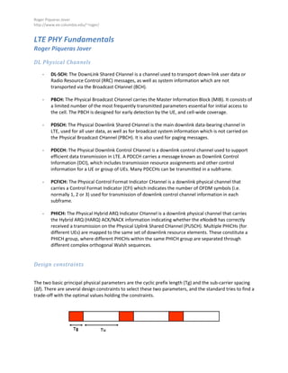
The two basic principal physical parameters are the cyclic prefix length (Tg) and the sub-carrier spacing
(Δf). There are several design constraints to select these two parameters, and the standard tries to find a
trade-off with the optimal values holding the constraints.
2. Roger Piqueras Jover
http://www.ee.columbia.edu/~roger/
First of all, Tu should be as larger than Tg as possible so the system has low overhead (Tu >> Tg). It is
important to keep in mind that Tu has to be sufficiently small to ensure that the channel does not vary
within one OFDM symbol.
Tg has to be large enough to avoid Inter Symbol Interference (ISI). This is, Tg should be larger than the
delay spread (Td) of the channel. LTE has different configurations depending on the type of channel
through which the system is transmitting (Tg > Td).
Finally, considering a mobile UE, there is going to be a deviation in frequency from the expected carrier
frequency. This is due to the Doppler Effect. This deviation in frequency will have a maximum value of
fdmax=v/λ0, being λ0 the wavelength associated to the systems carrier frequency. Note that the Doppler
Effect will be more noticeable at the further subcarriers from the DC component of the OFDM base-
band system.
In order to attenuate the effects of Inter Carrier Interference (ICI), it is required that fdmax/Δf << 1. This
implies that Δf has to be large enough to overcome ICI (Δf >> fdmax).
Recall that Tu=1/Δf, so one has to find a trade-off between Tu/Tg and Δf.
Delay spread
- Urban environment (maximum delay spread of 15μs): Among the 3 possible configurations listed
in the LTE standard, in this kind of environment the chosen parameters would be Δf=15KHz and
CP=17μs (Extended CP mode). This value of Δf is the most common one and is determined in
order to be able to serve users moving at a velocity of up to 500km/h. The chosen length of the
cyclic prefix is enough to avoid ISI.
3. Roger Piqueras Jover
http://www.ee.columbia.edu/~roger/
- Indoor environment (maximum delay spread of 1μs): In this case, the chosen parameters would
be Δf=15KHz and CP=5μs (Normal parametrization). Again, the chosen value of Δf would be
enough to cover speeds of up to 500km/h and a shorter CP s enough to avoid ISI with a delay
spread of 1μs.
Mapping of reference signals
The cell-specific reference signals are pilot signals inserted into the downlink signal that are used by the
UE to perform downlink channel estimation in order to perform coherent demodulation of the
information-bearing parts of the downlink signal. These signals are modulated using QPSK to make them
resilient to noise and errors and they carry one of the 504 different cell identities. They are also
transmitted in a power boosted way (6dB more than surrounding data symbols) so they are easily
detected, received and demodulated.
It can be shown that in an OFDM-based system an equidistant arrangement of reference symbols in the
lattice structure achieves the minimum mean squared error estimate of the channel. Moreover, in the
case of a uniform reference symbol grid, a ‘diamond shape’ in the time-frequency plane can be shown to
be optimal.
The placing of these reference signals in the time-frequency lattice is constrained both in time and
frequency.
Time domain requirements:
The required spacing in the time domain between reference signals is forced by the Doppler Effect. The
maximum Doppler frequency determines how fast the channel changes in time (coherence time
τc~1/fdmax). The LTE standard considers speeds of up to 500km/h. At a carrier frequency of 2GHz, this
speed represents a maximum Doppler shift of fdmax~ 950Hz. Given Nyquist’s sampling theorem, the
minimum sampling period required to reconstruct a channel with a Doppler shift of 950Hz is
Tmin=1/(2fdmax)≈0.5ms under the above assumptions. This implies that two reference symbols per slot
are needed in the time domain in order to estimate the channel correctly.
Frequency domain requirements
The required spacing in the frequency domain between reference signals s forced by the Coherence
Bandwidth of the channel. This bandwidth can be defined in different ways depending on the degree of
decorrelation in percentage. For example, a 50% coherence bandwidth is defined as the separation in
frequency such that the cross correlation between two frequency samples of the channel is 0.5.
The coherence bandwidth of the wireless channel si directly related to the Delay Spread (δτ) of the
channel. The coherence bandwith (50% and 90%) can be approximated as Bc,90%=1/(50 δτ) and
Bc,50%=1/(5δτ). The maximum r.m.s channel delay spread considered in the standard is 991 ns,
corresponding to Bc,90%≈20KHz and Bc,50%≈200KHz.
In LTE the spacing between two reference symbols in frequency, in one RB, is 45 kHz, thus allowing
the expected frequency domain variations of the channel to be resolved. Therefore, in the frequency
direction there is one reference symbol every six subcarriers on each OFDM symbols which includes
4. Roger Piqueras Jover
http://www.ee.columbia.edu/~roger/
reference symbol, but these are staggered so that within each Resource Block (RB) there is one
reference symbol every 3 subcarriers.
LTE FDD DL radio frame
a) Radio frame structure (1.4MHz BW, 1 antenna port, CFI=2)
b) Overhead and peak rate throughput (64-QAM, 5.5547 bits per symbol)
CFI=2
Given the BW of 1.4MHz, there are only 6 RBs available. For CFI=2 the structure of the frame is the same
as the one depicted in section (6.a). As can be seen above, there are 6x10=60 blocks of (1RB x 1
subframe), organized in 10 columns with 6 RB each one.
8 of the columns will be of the type a (shown above), 1 column of type a and 1 column of type c. Let’s
compute the number of resource elements used for data and the ones used for control information per
each time of column:
5. Roger Piqueras Jover
http://www.ee.columbia.edu/~roger/
- Column (a): CFI + PBCH + reference + PSS/SSS= 2x12+6x12+4=100 control resource elements
12x14-100= 68 data resource elements
- Column (b): CFI + reference + PSS/SSS= 2x12+2x12+6= 54 control resource elements
12x14-54= 114 data resource elements
- Column (c): CFI + reference= 2x12+6=30 control resource elements
12x14-30= 138 data resource elements
The overhead can be calculated as:
Total control=(1 column a)x(6x100)+(1 column b)x(6x54)+(8 columns c)x(6x30)=2364 resource elements
Total resource elements=(6x12)x(10x14)=10080
Overhead (CFI=2)= 100 x (2364/10080)=23.45%
One information symbol can be allocated in each data resource element. The transmission is done by
means of 64-QAM with an average of 5.5547 bits per symbol. The peak rate thorughput is:
Total data=(1 column a)x(6x68)+(1 column b)x(6x114)+(8 columns c)x(6x138)=7716 resource elements
Peak rate= (7716 symbols x 5.5547 bits/symbol)/10ms= 4.28Mbps
CFI=3
With CFI=3, the number of data and control resource elements in each column changes as follows:
- Column (a): CFI + PBCH + reference + PSS/SSS= 3x12+6x12+4=112 control resource elements
12x14-112= 56 data resource elements
- Column (b): CFI + reference + PSS/SSS= 3x12+2x12+6= 66 control resource elements
12x14-66= 102 data resource elements
- Column (c): CFI + reference= 3x12+6=42 control resource elements
12x14-42= 126 data resource elements
Total control=1x(6x112)+1x(6x66)+8x(6x42)=3084 resource elements
Total resource elements=(6x12)x(10x14)=10080
Overhead (CFI=2)= 100 x (3084/10080)=30.59%
Total data=(1 column a)x(6x56)+(1 column b)x(6x10²)+(8 columns c)x(6x126)=6996 resource elements
Peak rate= (6996 symbols x 5.5547 bits/symbol)/10ms= 3.89 Mbps
6. Roger Piqueras Jover
http://www.ee.columbia.edu/~roger/
CFI=4
With CFI=4, the number of data and control resource elements in each column changes as follows:
- Column (a): CFI + PBCH + reference + PSS/SSS= 4x12+6x12+4=124 control resource elements
12x14-124= 44 data resource elements
- Column (b): CFI + reference + PSS/SSS= 4x12+2x12+6= 78 control resource elements
12x14-78= 90 data resource elements
- Column (c): CFI + reference= 4x12+6=54 control resource elements
12x14-54= 114 data resource elements
Total control=1x(6x124)+1x(6x78)+8x(6x54)=3804 resource elements
Total resource elements=(6x12)x(10x14)=10080
Overhead (CFI=2)= 100 x (3804/10080)=37.74%
Total data=(1 column a)x(6x44)+(1 column b)x(6x90)+(8 columns c)x(6x114)=6276 resource elements
Peak rate= (6276 symbols x 5.5547 bits/symbol)/10ms= 3.48 Mbps
So, the final results are as shown in the table:
Scenario CFI Overhead [%] Peak rate [Mbps]
1 2 23.45 4.28
2 3 30.59 3.89
3 4 37.74 3.48
7. Roger Piqueras Jover
http://www.ee.columbia.edu/~roger/
LTE FDD DL radio frame (BW=20MHz)
a) Radio frame structure (20MHz BW, 4 antenna ports, CFI=2)
b) Overhead and peak rate throughput (64-QAM, 5.5547 bits per symbol)
Given 20MHz of available spectrum, there are 100 Resource Blocks available. Note that the 6 central
ones contain PBCH, PSS/SSS, CFI and the reference signals (for a 4 antenna port configuration) while The
remaining 94 RBs contain only CFI and the reference signals.
8. Roger Piqueras Jover
http://www.ee.columbia.edu/~roger/
CFI=1
Let’s recalculate the amount of data and control block per each kind of subframe:
- Column (a): CFI + PBCH + reference + PSS/SSS= 1x12+6x12+12=96 control resource elements
12x14-96= 72 data resource elements
- Column (b): CFI + reference + PSS/SSS= 1x12+2x12+20= 56 control resource elements
12x14-64= 112 data resource elements
- Column (c): CFI + reference= 1x12+20=32 control resource elements
12x14-40= 136 data resource elements
The overhead can be calculated as:
Total control=(1 column a)x(6x96)+(1 column b)x(6x56)+(8 columns c)x(6x32) +
+ (94x10 columns c)x32=32528 resource elements
Total resource elements=(100x12)x(10x14)=168000
Overhead (CFI=2)= 100 x (32528/168000)=19.36%
One information symbol can be allocated in each data resource element. The transmission is done by
means of 64-QAM with an average of 5.5547 bits per symbol. The peak rate thorughput is:
Total data=(1 column a)x(6x72)+(1 column b)x(6x112)+(8 columns c)x(6x136) +
+ (94x10 columns c)x136=135472 resource elements
Peak rate= 4 x (135472 symbols x 5.5547 bits/symbol)/10ms= 301 Mbps
CFI=2
Let’s recalculate the amount of data and control block per each kind of subframe:
- Column (a): CFI + PBCH + reference + PSS/SSS= 2x12+6x12+8=104 control resource elements
12x14-104= 64 data resource elements
- Column (b): CFI + reference + PSS/SSS= 2x12+2x12+16= 64 control resource elements
12x14-64= 104 data resource elements
- Column (c): CFI + reference= 2x12+16=40 control resource elements
12x14-40= 128 data resource elements
The overhead can be calculated as:
Total control=(1 column a)x(6x10⁴)+(1 column b)x(6x64)+(8 columns c)x(6x40) +
+ (94x10 columns c)x40=40528 resource elements
Total resource elements=(100x12)x(10x14)=168000
9. Roger Piqueras Jover
http://www.ee.columbia.edu/~roger/
Overhead (CFI=2)= 100 x (40528/168000)=24.12%
One information symbol can be allocated in each data resource element. The transmission is done by
means of 64-QAM with an average of 5.5547 bits per symbol. The peak rate thorughput is:
Total data=(1 column a)x(6x64)+(1 column b)x(6x10⁴)+(8 columns c)x(6x128) +
+ (94x10 columns c)x128=127472 resource elements
Peak rate= 4 x (127472 symbols x 5.5547 bits/symbol)/10ms= 283.23 Mbps
CFI=3
Let’s recalculate the amount of data and control block per each kind of subframe:
- Column (a): CFI + PBCH + reference + PSS/SSS= 3x12+6x12+8=116 control resource elements
12x14-116= 52 data resource elements
- Column (b): CFI + reference + PSS/SSS= 3x12+2x12+16= 76 control resource elements
12x14-76= 92 data resource elements
- Column (c): CFI + reference= 3x12+16=52 control resource elements
12x14-52= 116 data resource elements
The overhead can be calculated as:
Total control=(1 column a)x(6x116)+(1 column b)x(6x76)+(8 columns c)x(6x52) +
+ (94x10 columns c)x52=52528 resource elements
Total resource elements=(100x12)x(10x14)=168000
Overhead (CFI=2)= 100 x (52528/168000)=31.27%
One information symbol can be allocated in each data resource element. The transmission is done by
means of 64-QAM with an average of 5.5547 bits per symbol. The peak rate thorughput is:
Total data=(1 column a)x(6x52)+(1 column b)x(6x92)+(8 columns c)x(6x116) +
+ (94x10 columns c)x116=115472 resource elements
Peak rate= 4 x (115472 symbols x 5.5547 bits/symbol)/10ms= 256.56 Mbps
So, the final results are as shown in the table:
Scenario CFI Overhead [%] Peak rate [Mbps]
1 1 19.36 301
2 2 24.12 283.23
3 3 31.27 256.56
We observe that, as stated in the standard, the peak bit-rate of LTE is about 300 Mbps.