The document provides a comprehensive overview of UMTS channels, including physical, transport, and logical channels, along with their attributes and functionalities. It discusses various multiple access techniques such as FDMA, TDMA, and CDMA, and details specific downlink and uplink physical channels, including their frame structures. Additionally, the document covers transport channel attributes, including transport block and transport format combinations, as well as the mapping of logical channels to transport channels.

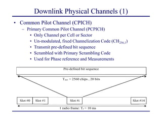
![Common Pilot Channel frame structure
– Secondary Common Pilot Channel (SCPICH) [Optional]
• Any Channelization Code with SF 256 (CH256,x)
• Scrambled with Primary or Secondary Scrambling Code
• Specific usage with narrow antenna beams in “hot spots” or
“high traffic density areas”](https://image.slidesharecdn.com/umtschanneloverview-240727113815-0c9ae3e2/85/UMTS-Channel-Overview-Transport-logical-8-320.jpg)