Downloaded 4,349 times
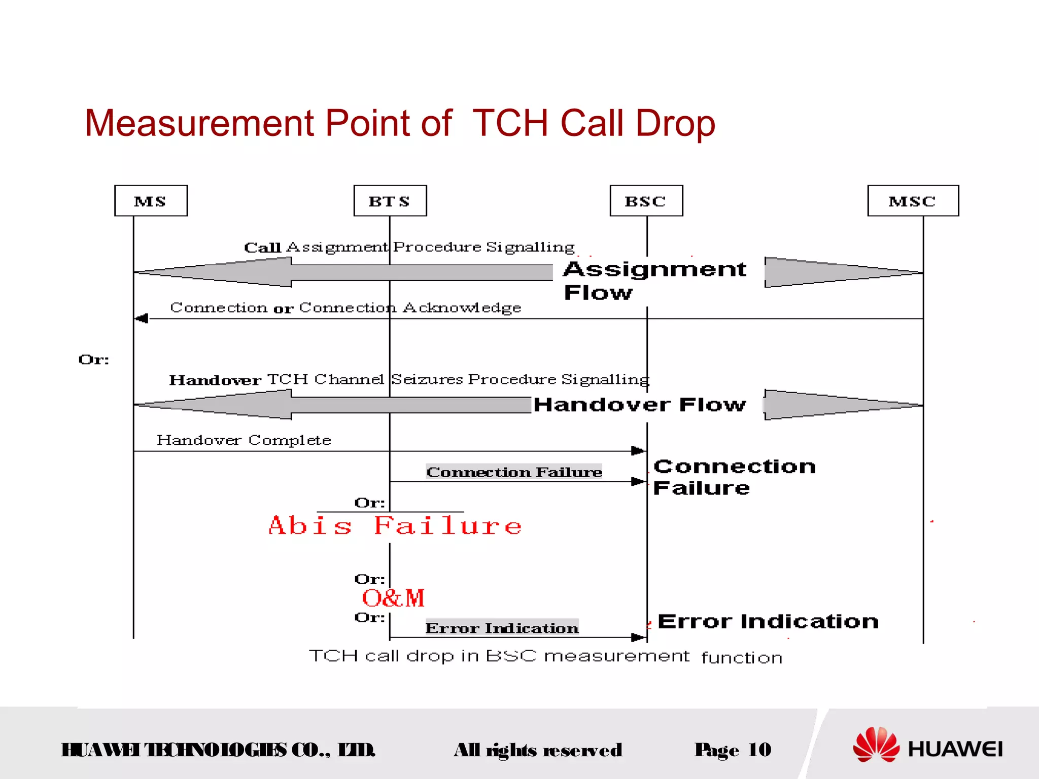
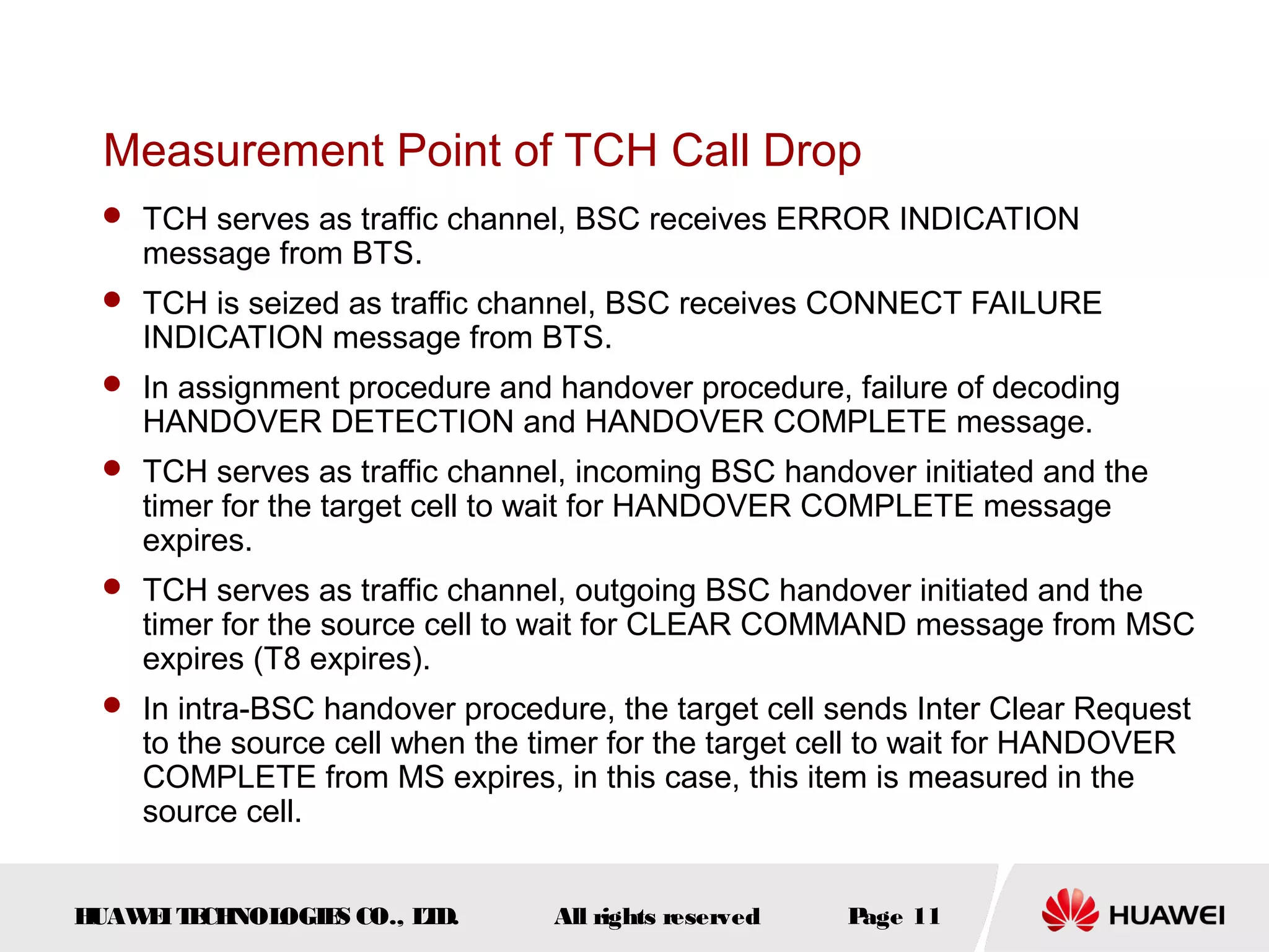
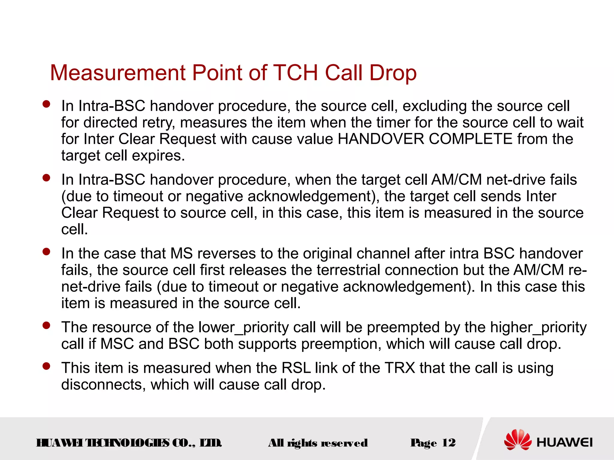
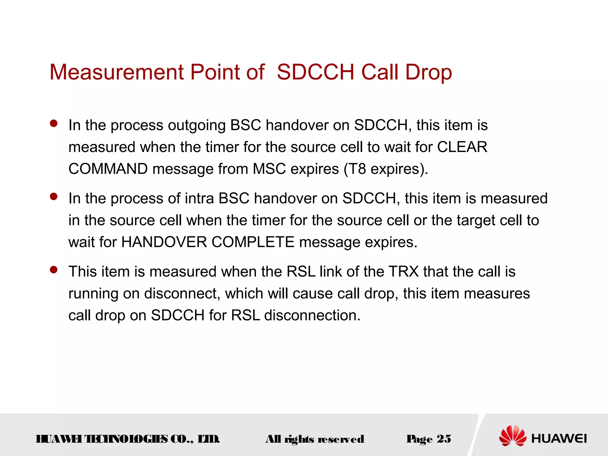
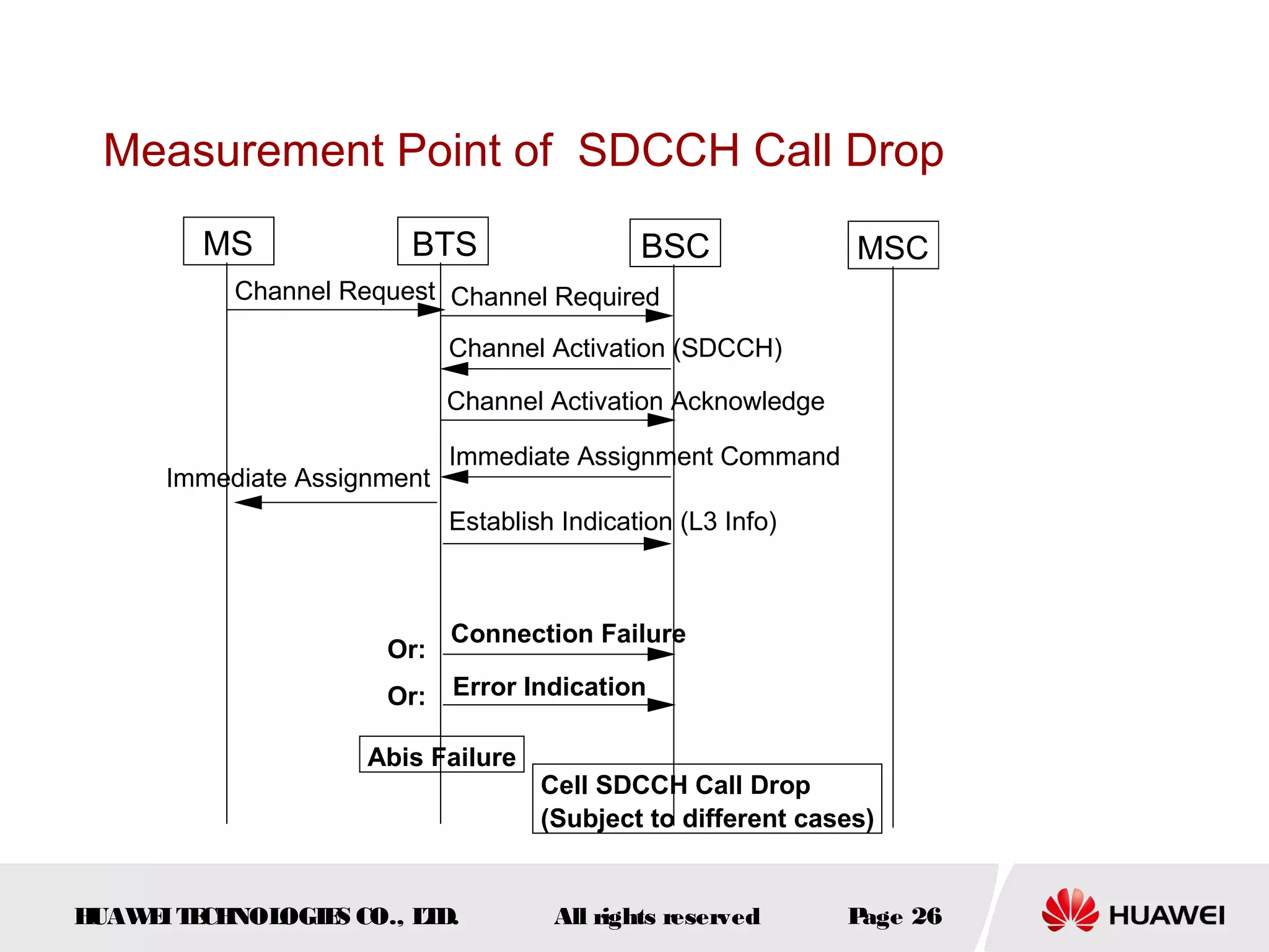
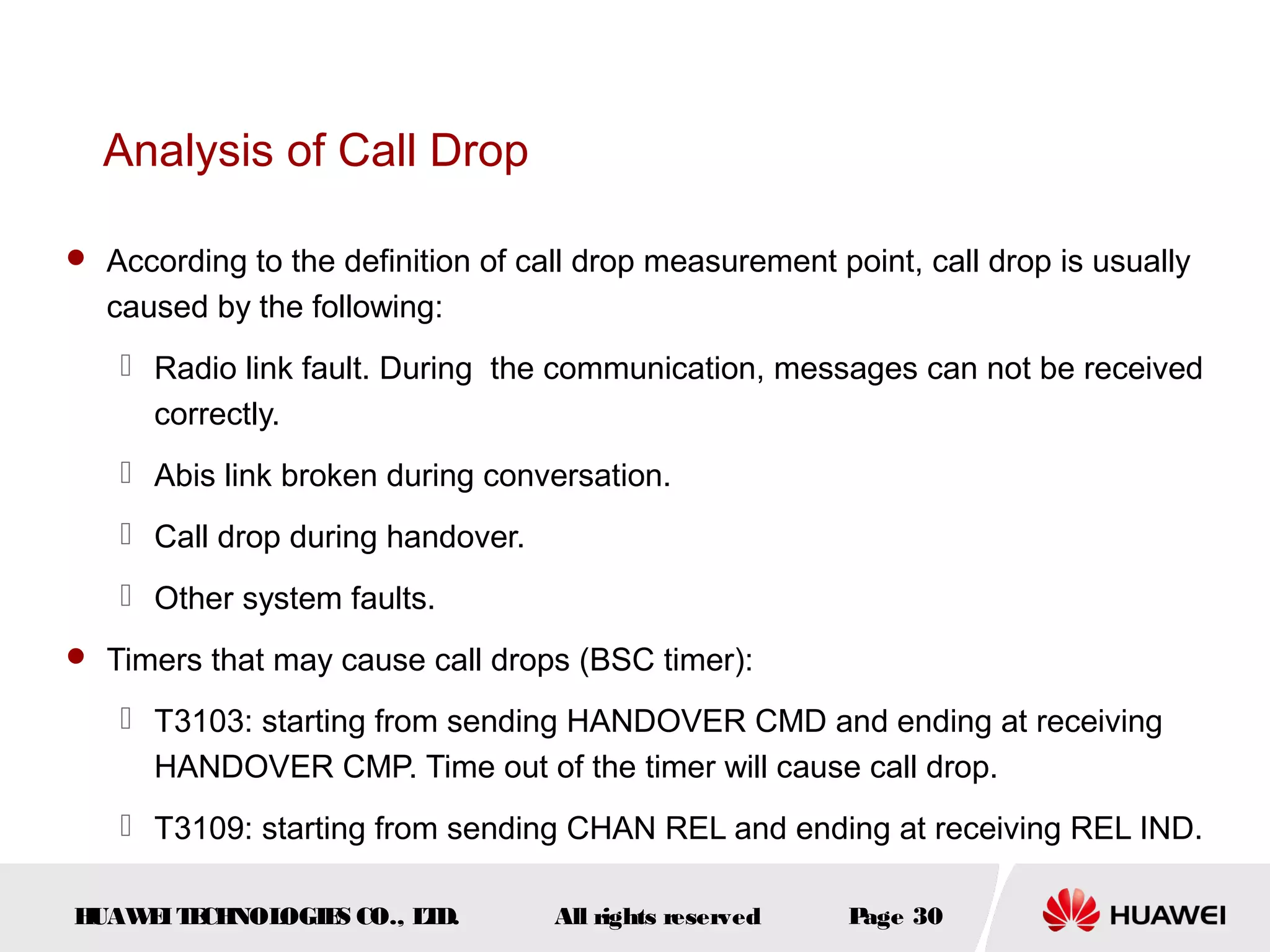
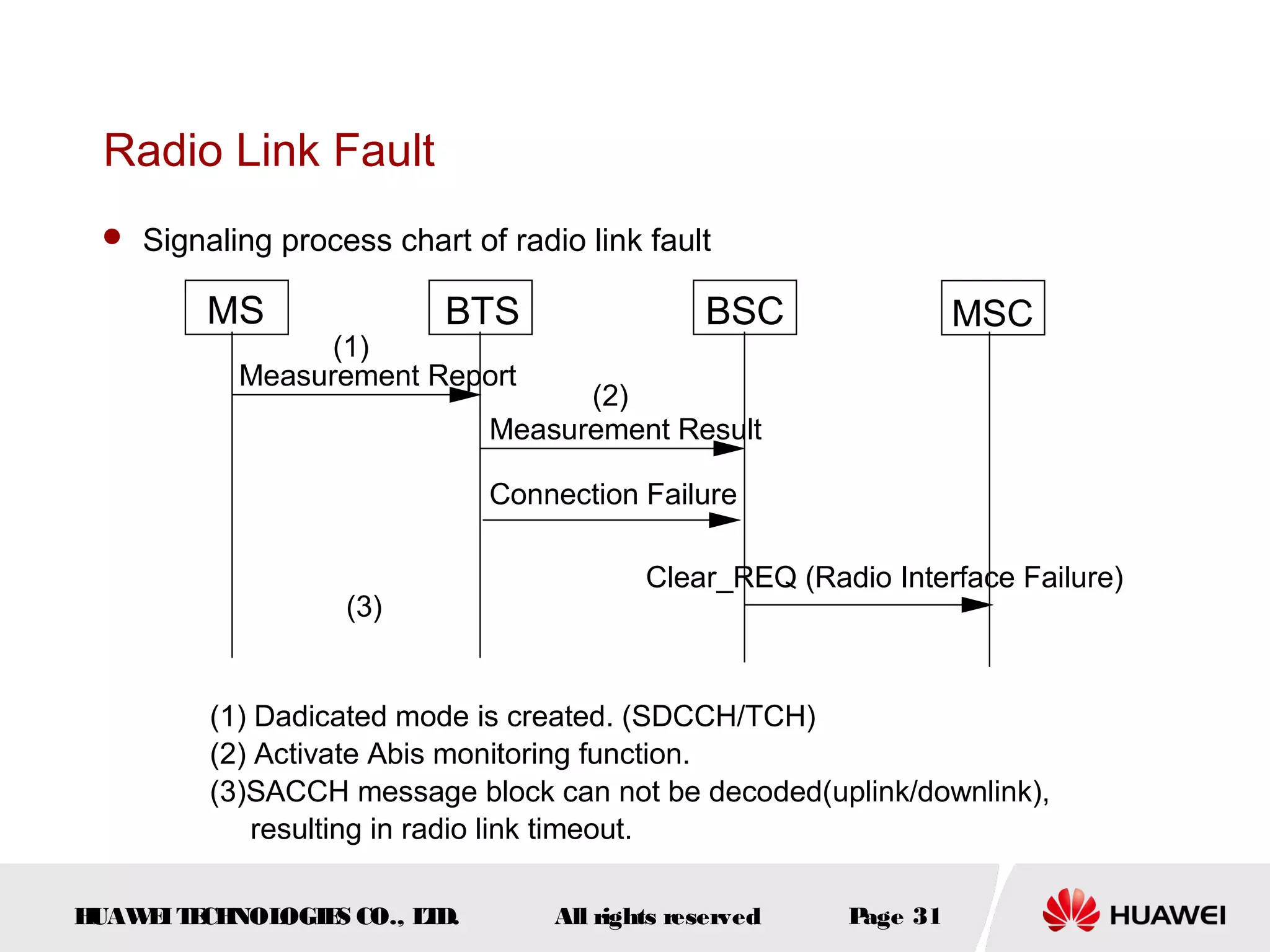
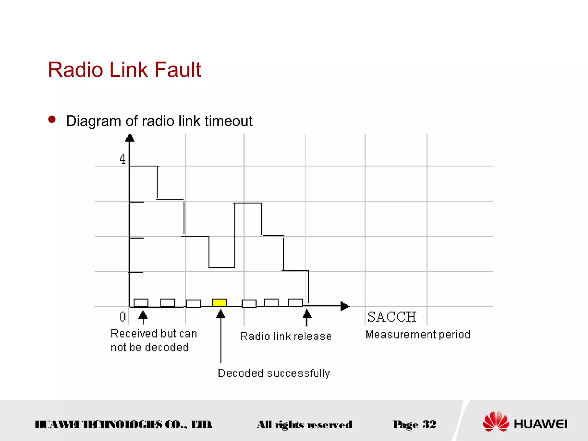
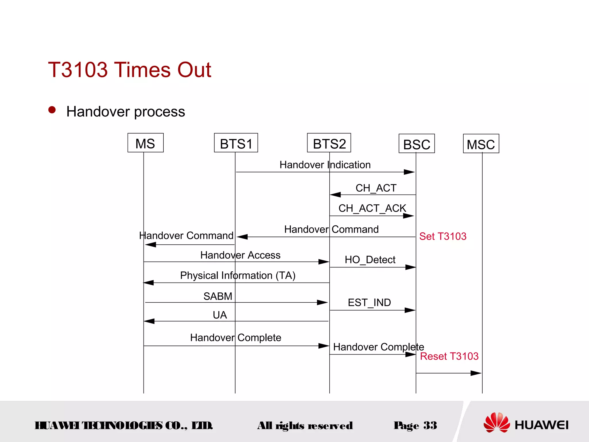
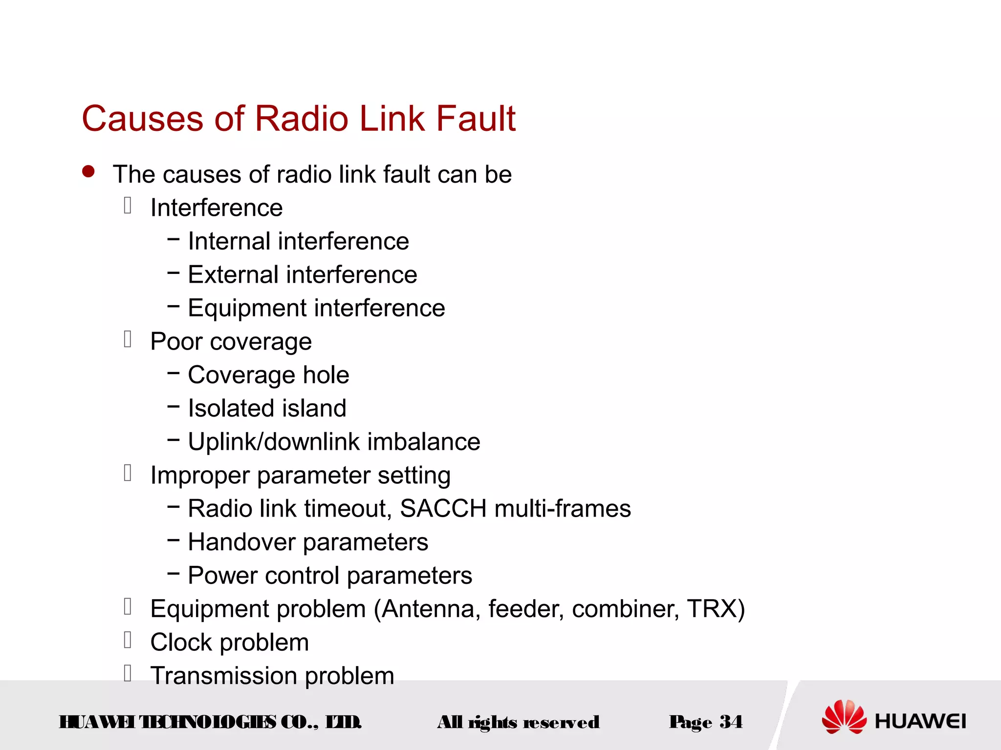

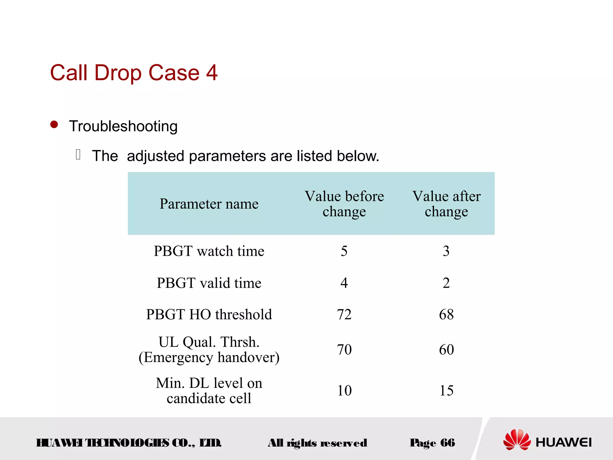


The document discusses call drop issues in mobile networks. It begins by defining call drop as the abnormal release of traffic or signaling channels after successful seizure. It then provides formulas to calculate call drop rates and describes measurement points to analyze call drops. Finally, it analyzes common causes of high call drop rates such as radio link faults, handover failures, and timer expirations.


![Kpi analysis[1]](https://cdn.slidesharecdn.com/ss_thumbnails/kpianalysis1-131018084316-phpapp01-thumbnail.jpg?width=640&height=640&fit=bounds)


