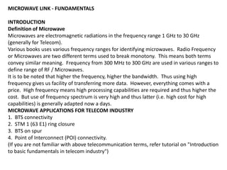
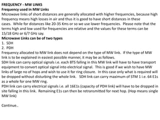
SlideShare a Scribd company logo
MICROWAVE LINK - FUNDAMENTALS
INTRODUCTION
Definition of Microwave
Microwaves are electromagnetic radiations in the frequency range 1 GHz to 30 GHz
(generally for Telecom).
Various books uses various frequency ranges for identifying microwaves. Radio Frequency
or Microwaves are two different terms used to break monotony. This means both terms
convey similar meaning. Frequency from 300 MHz to 300 GHz are used in various ranges to
define range of RF / Microwaves.
It is to be noted that higher the frequency, higher the bandwidth. Thus using high
frequency gives us facility of transferring more data. However, everything comes with a
price. High frequency means high processing capabilities are required and thus higher the
cost. But use of frequency spectrum is very high and thus latter (i.e. high cost for high
capabilities) is generally adapted now a days.
MICROWAVE APPLICATIONS FOR TELECOM INDUSTRY
1. BTS connectivity
2. STM 1 (63 E1) ring closure
3. BTS on spur
4. Point of Interconnect (POI) connectivity.
(If you are not familiar with above telecommunication terms, refer tutorial on "Introduction
to basic fundamentals in telecom industry")
FREQUENCY - MW LINKS
Frequency used in MW Links
Microwave links of short distances are generally allocated with higher frequencies, because high
frequency means high losses in air and thus it is good to have short distances in these
cases. While for distances like 20-35 Kms or so we use lower frequencies. Please note that the
terms high and low used for frequencies are relative and the values for these terms can be
15/18 GHz or 6/7 GHz say.
Microwave Links can be of two types
1. SDH
2. PDH
Frequency allocated to MW link does not depend on the type of MW link. If the type of MW
link is to be explained in easiest possible manner, it may be as follows.
SDH link can carry optical signals i.e. each BTS falling in this MW link will have to have transport
equipment to convert optical signal into electrical signal. This is good if we wish to have MW
links of large no of hops and wish to use it for ring closure. In this case only what is required will
be dropped without disturbing the whole link. SDH link can carry maximum of STM 1 i.e. 64 E1s
as a whole for one MW ring.
PDH link can carry electrical signals i.e. all 16E1s (capacity of PDH link) will have to be dropped in
site falling in this link. Remaining E1s can then be retransmitted for next hop. (Hop means single
MW link)
Continue..
SOME PARAMETERS
For 15 GHz link, Tx and Rx bandwidth is 28
MHz. Tx and Rx separation is 420 MHz. This
separation is defined by ITU and is there to
avoid interference.
For 6 GHz link Tx and Rx separation is 152 MHz.
For 7 GHz link Tx and Rx separation is 154 MHz.
PRACTICAL VIEW - MW LINKS
If we wish to look at practical implementation of MW links in telecom industry, we can start from
Fig MW.4.1
Fig MW.4.1 General MW Link Setup in Field
In Door Unit (IDU) which resides in Shelter, acts as Modem i.e. Modulator and Demodulator. It
takes electrical / optical signal and convert it into analog (electromagnetic) which is sent to ODU
(Out Door Unit).
IF cable is a co-axial cable which carries Intermediate Frequency. Details of IF cable can be seen
in Fig MW.4.2. You can feel free to ignore this figure and continue. Generally, maximum
permissible length of IF cable from IDU to ODU is 300m and frequency do not exceed 2 GHz.
Fig MW.4.2 IF Cable
Continue..
ODU is present just near MW antenna at height in tower. ODU performs upconversion (acts
as Mixer) to convert signal into required frequency allocated. For doing this ODU also have
high power amplifiers and filters. Since ODU output is high frequency cable connecting
ODU to antenna is "RF Low Loss Cable". Generally, for 6/7 GHz link this low loss cable is
used and for 15/18 GHz link waveguide is used to connect ODU to antenna.
POLARIZATION
Polarization defines the way of movement of MW waves in air. It can be either Linear or
Circular.
Type of Polarization
1. Linear - can be sub-divided into Vertical and Horizontal
2. Circular
VERTICAL POLARIZATION
An electromagnetic wave is said to be following Vertical Polarization if its electrical component is
perpendicular to the horizon of earth as shown in Fig MW.5.1
Fig MW.5.1 Vertical Polarization
HORIZONTAL POLARIZATION
An electromagnetic wave is said to be following Horizontal Polarization if its electrical
component is parallel to the horizon of earth as shown in Fig MW.5.2
Fig MW.5.2 Horizontal Polarization
CIRCULAR POLARIZATION
An electromagnetic wave is said to be following Circular Polarization if it radiates electric and
magnetic field in all directions i.e. they keep on rotating. Phase is the deciding factor
here. Don't worry about this... We generally do not use this in MW links.
WHICH POLARIZATION IS BETTER FOR MW LINKS?
There is no straight forward answer for this question. Definitely one can point out Vertical
Polarization as the best in first view because it is more prone to rain fading. Rain droplets are
generally flattened with increase in size (See Fig MW.5.3) and thus Vertical polarization is more
prone and less affected. However, horizontal polarization is very much used to avoid
interference, in case nearby areas are using Vertical Polarization. (See Fig MW.5.4)
So, vertical polarization is generally used for high frequency links, because high frequencies are
more prone to rain fading and horizontal polarization is generally used to avoid
interference. However, this cannot be treated as rule. Each operator is free to decide.
Fig MW.5.3 Rain Droplets Fig MW.5.4 Use of V and H Polarization to avoid interference
FACTORS AFFECTING MW LINK
Following major phenomenon affect MW Link
1. REFLECTION
2. REFRACTION
3. DIFFRACTION
4. SCATTERING
5. ABSORPTION
Factors affecting MW link - REFLECTION
REFLECTION
Reflection is one of the major factors that affect MW link. Fig MW.7.1 explains this
phenomenon.
Water is good reflector. Reflected Wave can have different phase and amplitude as compared
to LOS wave. Thus, this causes Fading of signal at receiver and this fading is called Multi Path
Fading.
To overcome this problem, we either adjust antenna heights at two ends to avoid major source
of reflection or to reduce its intensity. Another solution is to use Space Diversity, about which
we will study later in this tutorial.
NOTE:
Trees are good absorbers. So, if trees are present in between MW link, chances of reflection
reduces drastically.
Fig MW.7.1 Reflection in MW Link
Factors affecting MW link - REFRACTION
DO YOU KNOW THIS ?
Theory says that MW / electromagnetic waves travel in a straight line and yes, they do so in
vacuum. But when it comes to atmosphere, it may come as surprise to most of us that MW
waves do not travel in a straight line. Phenomenon responsible for this is REFRACTION. Density
in atmosphere is not uniform. It varies from one place to another. As we all know that light ray
bends towards or away from normal as it moves from higher density medium to lower or vice
versa, we can easily understand why MW waves deviate from straight line path in atmosphere.
In homogeneous atmosphere vertical change in dielectric constant is gradual and hence bending
or refraction is continuous. Ray is bent from thinner density air towards thicker making it follow
earth curvature. This can be related with radii of spheres. First radius is of earth (6370 Km
approx) and second is formed by curvature of beam of ray with its center coinciding center of
earth.
We can define K Factor using above information
K-Factor = R / R`
where
R = Radius of ray beam curvature
R` = Radius of earth
K=4/3 for earth's atmosphere.
Fig MW.8.1 shows value of K according to path traveled by MW wave.
Fig MW.8.1 K-Factor in MW Link
Factors affecting MW link - Diffraction, Scattering & Absorption
DIFFRACTION
Diffraction of wave occurs when bending takes place at sharp irregular edges. This diffracted
wave can interfere very much with desired signal.
SCATTERING
Scattering of ray of light occurs when object it strikes is of smaller size that its own wavelength.
ABSORPTION
Above 10 GHz, absorption in atmosphere becomes dominant. Rain droplets become
comparable to wavelength.
This absorption can be 2 dB/Km or can be as high as 3 dB/Km in case of rain.
DIVERSITY IN MW LINKS
Diversity in MW Links is a sort of redundancy in network. They also help overcome various
factors which affect MW links.
Two types of Diversity in MW links
1. Frequency Diversity
2. Space Diversity
Fig MW.10.1 and MW.10.2 shows these diversities respectively.
Frequency Diversity calls for use of two different frequencies for same MW link. This is normally
avoided because two frequency allocation means double the annual fee payable for frequency.
Frequency diversity is generally meant to overcome frequency interferences and various other
factors.
Space Diversity uses two MW antennas at each side and is best suited to overcome Reflection of
MW waves. Signal is received by both antennas called Main Antenna and Diversity Antenna and
it is IDU to decide which signal to receive. Generally IDU receives best possible signal. This
diversity also helps a lot in areas of high wind because if one antenna gets misaligned network
can function without fail from another. Thus this provides a sort of redundancy to our network.
FREE SPACE LOSS
Free Space Loss is defined as minimum loss an electromagnetic wave experiences if it travels in
atmosphere. It depends from place to place. Its value for Kerela and Rajasthan will be different
due to various factors one of which can be humidity. However, we may roughly define free
space loss for MW link as
Lfs = 92.45 + 20 log (dist * freq)
where
dist = MW hop length in Kms.
freq = Frequency of MW link in GHz.
EXAMPLE
For MW link of 15 GHz and hop length 10 Kms free space loss can roughly be calculated as
= 92.45 + 20 log ( 10 * 15)
= 135.97 dB
ANTENNA GAIN
Antenna Gain is the gain antenna provides to the signal before transmitting it into air. For
parabolic antennas used for MW link, this gain is roughly
Antenna Gain = 17.8 + 20 log (f * dia)
where
f = Frequency in GHz
dia = Diameter of MW antenna.
EXAMPLE
For 18 GHz MW link and 0.3 m size MW antenna, Antenna Gain will be approx
= 17.8 + 20 log (18*0.3)
= 32.44 dBi
(Don't worry about unit dBi, refer tutorial "Introduction to dB" elsewhere on this website. To
learn more about antennas refer tutorial on it.)
FRESNEL ZONE
To understand Fresnel zone we need to first refer Fig MW.12.1
From the figure above we can see that apart from direct line of sight (LOS) we need to leave
some space above and below it to allow deviation of MW wave from its original path. This
deviation, as already studied, is due to refraction. Fresnel zone is nothing but distance below
and above a point which should be clear for LOS communication.
where
rn = radius of fresnel zone. Generally we consider n=1 i.e. first fresnel zone clearance.
d1 = distance of point from Point A
d2 = distance of point from Point B
Lambda = Wavelength
Fig MW.12.1 MW Communication
LINK BUDGET
Now we will see link budget of MW link i.e. we will analyze gains and losses and calculate
received power at other end.
Refer Fig MW.13.1 before moving further.
Fig MW.13.1 Link Budget for MW Link
From Fig MW.13.1 it can be seen clearly that received power at Point B can be calculated as
RxA = TxA + GA - Lfs - Arain + GB
where
TxA = Transmit Power
GA = Gain of Antenna A
Lfs = Free Space Loss
Arain = Attenuation due to rain
GB = Gain of Antenna B
EXAMPLE
Suppose we have 6.2 GHz MW link. Diameter of antenna at both sides is 1.8 m. Distance is 20
Kms. Calculate approx received power at point B, if transmitted power at point A is 25 dBm.
SOLUTION
First we will calculate Gain of two antennas. Since diameter is same, both antennas will roughly
have gain of
= 17.8 + 20 log (freq * dia)
= 17.8 + 20 log (6.2 * 1.8)
= 38.753 dBi
Then, we will calculate rough free space loss as
= 98.45 + 20 log (dist * freq)
= 98.45 + 20 log (20 * 6.2)
= 140.318 dBm
Finally we will calculate received power at Point B from above given formula. We are assuming
rain attenuation as zero.
RxB = 25 + 38.753 - 140.318 - 0 + 38.753
= - 37.812 dBm Answer
NOTE
Receiver sensitivity is generally around -65 dBm and hence the receive power we are getting is
good and also take care of rain attenuation margin during rainy season. It is good practice to
leave around 30 dB as rain margin.
Mw links   fundamentals

More Related Content

What's hot

Radio Wave propagation
Radio Wave propagationRadio Wave propagation
Radio Wave propagation
Ritika De
 
Rf fundamentals
Rf fundamentalsRf fundamentals
Rf fundamentals
Sura Satish Babu
 
FUNDAMENTALS OF MICROWAVE RADIO COMMUNICATION FOR IP AND TDM
FUNDAMENTALS OF MICROWAVE RADIO COMMUNICATION FOR IP AND TDMFUNDAMENTALS OF MICROWAVE RADIO COMMUNICATION FOR IP AND TDM
FUNDAMENTALS OF MICROWAVE RADIO COMMUNICATION FOR IP AND TDM
Carlos Antonio Leal Saballos
 
Microwave Link Design - PTP Transmission
Microwave  Link Design - PTP TransmissionMicrowave  Link Design - PTP Transmission
Microwave Link Design - PTP Transmission
Mohamed Sewailam
 
Link budget calculation
Link budget calculationLink budget calculation
Link budget calculation
sitimunirah88
 
Antenna
AntennaAntenna
microwave-fundamentals
microwave-fundamentalsmicrowave-fundamentals
microwave-fundamentals
ATTO RATHORE
 
Basics of RF
Basics of RFBasics of RF
Types of microstrip antenna
Types of microstrip antenna Types of microstrip antenna
Types of microstrip antenna
NupurRathi7
 
microwave-communication-wave-guides
microwave-communication-wave-guidesmicrowave-communication-wave-guides
microwave-communication-wave-guides
ATTO RATHORE
 
Chapter#5
Chapter#5Chapter#5
radio-wave-propagation-presentations
radio-wave-propagation-presentationsradio-wave-propagation-presentations
radio-wave-propagation-presentations
ATTO RATHORE
 
Radio waves
Radio wavesRadio waves
Radio waves
Rama Charan
 
Microwave radio link design
Microwave radio link designMicrowave radio link design
Microwave radio link design
Engr Syed Absar Kazmi
 
1 survey system design_and_engg
1 survey system design_and_engg1 survey system design_and_engg
1 survey system design_and_engg
Muhammad Yahya
 
Chap 5 (small scale fading)
Chap 5 (small scale fading)Chap 5 (small scale fading)
Chap 5 (small scale fading)
asadkhan1327
 
Multichannel fading
Multichannel fadingMultichannel fading
Multichannel fading
Shree Krupa
 
Microwave Antenna -- MW Transmission
Microwave Antenna -- MW TransmissionMicrowave Antenna -- MW Transmission
Microwave Antenna -- MW Transmission
Mohamed Sewailam
 
4. free space path loss model part 2
4. free space path loss model   part 24. free space path loss model   part 2
4. free space path loss model part 2
JAIGANESH SEKAR
 
wave-guides
wave-guideswave-guides
wave-guides
ATTO RATHORE
 

What's hot (20)

Radio Wave propagation
Radio Wave propagationRadio Wave propagation
Radio Wave propagation
 
Rf fundamentals
Rf fundamentalsRf fundamentals
Rf fundamentals
 
FUNDAMENTALS OF MICROWAVE RADIO COMMUNICATION FOR IP AND TDM
FUNDAMENTALS OF MICROWAVE RADIO COMMUNICATION FOR IP AND TDMFUNDAMENTALS OF MICROWAVE RADIO COMMUNICATION FOR IP AND TDM
FUNDAMENTALS OF MICROWAVE RADIO COMMUNICATION FOR IP AND TDM
 
Microwave Link Design - PTP Transmission
Microwave  Link Design - PTP TransmissionMicrowave  Link Design - PTP Transmission
Microwave Link Design - PTP Transmission
 
Link budget calculation
Link budget calculationLink budget calculation
Link budget calculation
 
Antenna
AntennaAntenna
Antenna
 
microwave-fundamentals
microwave-fundamentalsmicrowave-fundamentals
microwave-fundamentals
 
Basics of RF
Basics of RFBasics of RF
Basics of RF
 
Types of microstrip antenna
Types of microstrip antenna Types of microstrip antenna
Types of microstrip antenna
 
microwave-communication-wave-guides
microwave-communication-wave-guidesmicrowave-communication-wave-guides
microwave-communication-wave-guides
 
Chapter#5
Chapter#5Chapter#5
Chapter#5
 
radio-wave-propagation-presentations
radio-wave-propagation-presentationsradio-wave-propagation-presentations
radio-wave-propagation-presentations
 
Radio waves
Radio wavesRadio waves
Radio waves
 
Microwave radio link design
Microwave radio link designMicrowave radio link design
Microwave radio link design
 
1 survey system design_and_engg
1 survey system design_and_engg1 survey system design_and_engg
1 survey system design_and_engg
 
Chap 5 (small scale fading)
Chap 5 (small scale fading)Chap 5 (small scale fading)
Chap 5 (small scale fading)
 
Multichannel fading
Multichannel fadingMultichannel fading
Multichannel fading
 
Microwave Antenna -- MW Transmission
Microwave Antenna -- MW TransmissionMicrowave Antenna -- MW Transmission
Microwave Antenna -- MW Transmission
 
4. free space path loss model part 2
4. free space path loss model   part 24. free space path loss model   part 2
4. free space path loss model part 2
 
wave-guides
wave-guideswave-guides
wave-guides
 

Viewers also liked

New final bsnl training report
New final bsnl training report New final bsnl training report
New final bsnl training report
manish katara
 
Microwave link communication system
Microwave link communication systemMicrowave link communication system
Microwave link communication system
billyjoe585
 
Terrestrial Microwave Link Design
Terrestrial Microwave Link DesignTerrestrial Microwave Link Design
Terrestrial Microwave Link Design
mohamud mire
 
Routing over ericsson mini link
Routing over ericsson mini linkRouting over ericsson mini link
Routing over ericsson mini link
Ahmed Nabeeh
 
Fundamentals of sdh
Fundamentals of sdhFundamentals of sdh
Fundamentals of sdh
sreejithkt
 
Basics Of Minilink Microwave Networks
Basics Of Minilink Microwave NetworksBasics Of Minilink Microwave Networks
Basics Of Minilink Microwave Networks
Atif Mahmood
 
S.cerevisiae Fluorescence Problem
S.cerevisiae Fluorescence ProblemS.cerevisiae Fluorescence Problem
S.cerevisiae Fluorescence Problem
poccopen
 
Tns Profile V 12.0
Tns Profile V 12.0Tns Profile V 12.0
Tns Profile V 12.0
jw
 
Mw presentation 1
Mw presentation 1Mw presentation 1
Mw presentation 1
Amizareza
 
Pdhsdh
PdhsdhPdhsdh
Pdh and sdh1
Pdh and sdh1Pdh and sdh1
Pdh and sdh1
Khant Oo
 
Molecular weight fundamentals
Molecular weight fundamentalsMolecular weight fundamentals
Molecular weight fundamentals
Vaaliban Naan
 
Microwave Transmission
Microwave TransmissionMicrowave Transmission
Microwave Transmission
Devang Bhatti
 
Sdh total final
Sdh total finalSdh total final
Sdh total final
Manish Desai
 
Mw training slide
Mw training slideMw training slide
Mw training slide
dedoyin
 
Microwave Antenna
Microwave AntennaMicrowave Antenna
Microwave Antenna
zarinamdamin
 
Digital microwave communication principles
Digital microwave communication principles Digital microwave communication principles
Digital microwave communication principles
Mohamed Sewailam
 
Throughput Calculation for LTE TDD and FDD System
Throughput Calculation for  LTE TDD and FDD SystemThroughput Calculation for  LTE TDD and FDD System
Throughput Calculation for LTE TDD and FDD System
Sukhvinder Singh Malik
 

Viewers also liked (18)

New final bsnl training report
New final bsnl training report New final bsnl training report
New final bsnl training report
 
Microwave link communication system
Microwave link communication systemMicrowave link communication system
Microwave link communication system
 
Terrestrial Microwave Link Design
Terrestrial Microwave Link DesignTerrestrial Microwave Link Design
Terrestrial Microwave Link Design
 
Routing over ericsson mini link
Routing over ericsson mini linkRouting over ericsson mini link
Routing over ericsson mini link
 
Fundamentals of sdh
Fundamentals of sdhFundamentals of sdh
Fundamentals of sdh
 
Basics Of Minilink Microwave Networks
Basics Of Minilink Microwave NetworksBasics Of Minilink Microwave Networks
Basics Of Minilink Microwave Networks
 
S.cerevisiae Fluorescence Problem
S.cerevisiae Fluorescence ProblemS.cerevisiae Fluorescence Problem
S.cerevisiae Fluorescence Problem
 
Tns Profile V 12.0
Tns Profile V 12.0Tns Profile V 12.0
Tns Profile V 12.0
 
Mw presentation 1
Mw presentation 1Mw presentation 1
Mw presentation 1
 
Pdhsdh
PdhsdhPdhsdh
Pdhsdh
 
Pdh and sdh1
Pdh and sdh1Pdh and sdh1
Pdh and sdh1
 
Molecular weight fundamentals
Molecular weight fundamentalsMolecular weight fundamentals
Molecular weight fundamentals
 
Microwave Transmission
Microwave TransmissionMicrowave Transmission
Microwave Transmission
 
Sdh total final
Sdh total finalSdh total final
Sdh total final
 
Mw training slide
Mw training slideMw training slide
Mw training slide
 
Microwave Antenna
Microwave AntennaMicrowave Antenna
Microwave Antenna
 
Digital microwave communication principles
Digital microwave communication principles Digital microwave communication principles
Digital microwave communication principles
 
Throughput Calculation for LTE TDD and FDD System
Throughput Calculation for  LTE TDD and FDD SystemThroughput Calculation for  LTE TDD and FDD System
Throughput Calculation for LTE TDD and FDD System
 

Similar to Mw links fundamentals

Wireless mobile charging using microwaves
Wireless mobile charging using microwavesWireless mobile charging using microwaves
Wireless mobile charging using microwaves
Devyani Vaidya
 
WIRELESS MOBILE CHARGING USING MICROWAVES
 WIRELESS MOBILE CHARGING USING MICROWAVES  WIRELESS MOBILE CHARGING USING MICROWAVES
WIRELESS MOBILE CHARGING USING MICROWAVES
JASHU JASWANTH
 
Wirelessmobilechargingusingmicrowavesjazz 140128114925-phpapp02
Wirelessmobilechargingusingmicrowavesjazz 140128114925-phpapp02Wirelessmobilechargingusingmicrowavesjazz 140128114925-phpapp02
Wirelessmobilechargingusingmicrowavesjazz 140128114925-phpapp02
Kartik Kalpande Patil
 
Microstrip Antenna for ISM Band (2.4GHz) Applications-A review
Microstrip Antenna for ISM Band (2.4GHz) Applications-A reviewMicrostrip Antenna for ISM Band (2.4GHz) Applications-A review
Microstrip Antenna for ISM Band (2.4GHz) Applications-A review
IJERA Editor
 
Wireless Transmission Network : A Imagine
Wireless Transmission Network : A ImagineWireless Transmission Network : A Imagine
Wireless Transmission Network : A Imagine
Ministry of New & Renewable Energy, Govt of India
 
Wireless Transmission Network : A Imagine
Wireless Transmission Network : A ImagineWireless Transmission Network : A Imagine
Wireless Transmission Network : A Imagine
Ministry of New & Renewable Energy, Govt of India
 
ECE2708 Microwave Engineering Lab Joournal
ECE2708 Microwave Engineering Lab JoournalECE2708 Microwave Engineering Lab Joournal
ECE2708 Microwave Engineering Lab Joournal
Chaitanya Vijaykumar Mahamuni
 
Multiband Microstrip Antenna for Wi-MAX Application-A study
Multiband Microstrip Antenna for Wi-MAX Application-A studyMultiband Microstrip Antenna for Wi-MAX Application-A study
Multiband Microstrip Antenna for Wi-MAX Application-A study
IJERA Editor
 
Circuits for Optical Based Line of Sight Voice Communication
Circuits for Optical Based Line of Sight Voice CommunicationCircuits for Optical Based Line of Sight Voice Communication
Circuits for Optical Based Line of Sight Voice Communication
journalBEEI
 
Planar Inverted-F Antenna for GPS Application - A study
Planar Inverted-F Antenna for GPS Application - A studyPlanar Inverted-F Antenna for GPS Application - A study
Planar Inverted-F Antenna for GPS Application - A study
IJERA Editor
 
waveguides-ppt
waveguides-pptwaveguides-ppt
waveguides-ppt
ATTO RATHORE
 
Study of multiple antennas with defected ground slot for low-band LTE applica...
Study of multiple antennas with defected ground slot for low-band LTE applica...Study of multiple antennas with defected ground slot for low-band LTE applica...
Study of multiple antennas with defected ground slot for low-band LTE applica...
journalBEEI
 
wirelesspowertransfer
wirelesspowertransferwirelesspowertransfer
wirelesspowertransfer
Yogitha R Malkireddy
 
Cladding effects on silica directional couplers
Cladding effects on silica directional couplersCladding effects on silica directional couplers
Cladding effects on silica directional couplers
TELKOMNIKA JOURNAL
 
Propagation_model5th unit.pptx
Propagation_model5th unit.pptxPropagation_model5th unit.pptx
Propagation_model5th unit.pptx
AshishChandrakar12
 
Dual band antenna using reactive loading
Dual band antenna using reactive loadingDual band antenna using reactive loading
Dual band antenna using reactive loading
Prathamesh Bhat
 
Basic antenna
Basic antennaBasic antenna
Basic antenna
Bilal Akram
 
BASIC CONCEPTS OF TRANSMISSION LINES & WAVEGUIDES ForC 18 DECE unit 1, SBTET
BASIC CONCEPTS OF TRANSMISSION LINES  &  WAVEGUIDES ForC 18 DECE unit 1, SBTETBASIC CONCEPTS OF TRANSMISSION LINES  &  WAVEGUIDES ForC 18 DECE unit 1, SBTET
BASIC CONCEPTS OF TRANSMISSION LINES & WAVEGUIDES ForC 18 DECE unit 1, SBTET
janakiravi
 
Ijmnct03
Ijmnct03Ijmnct03
Ijmnct03
ijmnct
 
Performance Analysis of Different Linearly Polarized Modes for Two Channel MD...
Performance Analysis of Different Linearly Polarized Modes for Two Channel MD...Performance Analysis of Different Linearly Polarized Modes for Two Channel MD...
Performance Analysis of Different Linearly Polarized Modes for Two Channel MD...
International Journal of Modern Research in Engineering and Technology
 

Similar to Mw links fundamentals (20)

Wireless mobile charging using microwaves
Wireless mobile charging using microwavesWireless mobile charging using microwaves
Wireless mobile charging using microwaves
 
WIRELESS MOBILE CHARGING USING MICROWAVES
 WIRELESS MOBILE CHARGING USING MICROWAVES  WIRELESS MOBILE CHARGING USING MICROWAVES
WIRELESS MOBILE CHARGING USING MICROWAVES
 
Wirelessmobilechargingusingmicrowavesjazz 140128114925-phpapp02
Wirelessmobilechargingusingmicrowavesjazz 140128114925-phpapp02Wirelessmobilechargingusingmicrowavesjazz 140128114925-phpapp02
Wirelessmobilechargingusingmicrowavesjazz 140128114925-phpapp02
 
Microstrip Antenna for ISM Band (2.4GHz) Applications-A review
Microstrip Antenna for ISM Band (2.4GHz) Applications-A reviewMicrostrip Antenna for ISM Band (2.4GHz) Applications-A review
Microstrip Antenna for ISM Band (2.4GHz) Applications-A review
 
Wireless Transmission Network : A Imagine
Wireless Transmission Network : A ImagineWireless Transmission Network : A Imagine
Wireless Transmission Network : A Imagine
 
Wireless Transmission Network : A Imagine
Wireless Transmission Network : A ImagineWireless Transmission Network : A Imagine
Wireless Transmission Network : A Imagine
 
ECE2708 Microwave Engineering Lab Joournal
ECE2708 Microwave Engineering Lab JoournalECE2708 Microwave Engineering Lab Joournal
ECE2708 Microwave Engineering Lab Joournal
 
Multiband Microstrip Antenna for Wi-MAX Application-A study
Multiband Microstrip Antenna for Wi-MAX Application-A studyMultiband Microstrip Antenna for Wi-MAX Application-A study
Multiband Microstrip Antenna for Wi-MAX Application-A study
 
Circuits for Optical Based Line of Sight Voice Communication
Circuits for Optical Based Line of Sight Voice CommunicationCircuits for Optical Based Line of Sight Voice Communication
Circuits for Optical Based Line of Sight Voice Communication
 
Planar Inverted-F Antenna for GPS Application - A study
Planar Inverted-F Antenna for GPS Application - A studyPlanar Inverted-F Antenna for GPS Application - A study
Planar Inverted-F Antenna for GPS Application - A study
 
waveguides-ppt
waveguides-pptwaveguides-ppt
waveguides-ppt
 
Study of multiple antennas with defected ground slot for low-band LTE applica...
Study of multiple antennas with defected ground slot for low-band LTE applica...Study of multiple antennas with defected ground slot for low-band LTE applica...
Study of multiple antennas with defected ground slot for low-band LTE applica...
 
wirelesspowertransfer
wirelesspowertransferwirelesspowertransfer
wirelesspowertransfer
 
Cladding effects on silica directional couplers
Cladding effects on silica directional couplersCladding effects on silica directional couplers
Cladding effects on silica directional couplers
 
Propagation_model5th unit.pptx
Propagation_model5th unit.pptxPropagation_model5th unit.pptx
Propagation_model5th unit.pptx
 
Dual band antenna using reactive loading
Dual band antenna using reactive loadingDual band antenna using reactive loading
Dual band antenna using reactive loading
 
Basic antenna
Basic antennaBasic antenna
Basic antenna
 
BASIC CONCEPTS OF TRANSMISSION LINES & WAVEGUIDES ForC 18 DECE unit 1, SBTET
BASIC CONCEPTS OF TRANSMISSION LINES  &  WAVEGUIDES ForC 18 DECE unit 1, SBTETBASIC CONCEPTS OF TRANSMISSION LINES  &  WAVEGUIDES ForC 18 DECE unit 1, SBTET
BASIC CONCEPTS OF TRANSMISSION LINES & WAVEGUIDES ForC 18 DECE unit 1, SBTET
 
Ijmnct03
Ijmnct03Ijmnct03
Ijmnct03
 
Performance Analysis of Different Linearly Polarized Modes for Two Channel MD...
Performance Analysis of Different Linearly Polarized Modes for Two Channel MD...Performance Analysis of Different Linearly Polarized Modes for Two Channel MD...
Performance Analysis of Different Linearly Polarized Modes for Two Channel MD...
 

Recently uploaded

BÀI TẬP BỔ TRỢ TIẾNG ANH LỚP 9 CẢ NĂM - GLOBAL SUCCESS - NĂM HỌC 2024-2025 - ...
BÀI TẬP BỔ TRỢ TIẾNG ANH LỚP 9 CẢ NĂM - GLOBAL SUCCESS - NĂM HỌC 2024-2025 - ...BÀI TẬP BỔ TRỢ TIẾNG ANH LỚP 9 CẢ NĂM - GLOBAL SUCCESS - NĂM HỌC 2024-2025 - ...
BÀI TẬP BỔ TRỢ TIẾNG ANH LỚP 9 CẢ NĂM - GLOBAL SUCCESS - NĂM HỌC 2024-2025 - ...
Nguyen Thanh Tu Collection
 
Your Skill Boost Masterclass: Strategies for Effective Upskilling
Your Skill Boost Masterclass: Strategies for Effective UpskillingYour Skill Boost Masterclass: Strategies for Effective Upskilling
Your Skill Boost Masterclass: Strategies for Effective Upskilling
Excellence Foundation for South Sudan
 
PCOS corelations and management through Ayurveda.
PCOS corelations and management through Ayurveda.PCOS corelations and management through Ayurveda.
PCOS corelations and management through Ayurveda.
Dr. Shivangi Singh Parihar
 
What is Digital Literacy? A guest blog from Andy McLaughlin, University of Ab...
What is Digital Literacy? A guest blog from Andy McLaughlin, University of Ab...What is Digital Literacy? A guest blog from Andy McLaughlin, University of Ab...
What is Digital Literacy? A guest blog from Andy McLaughlin, University of Ab...
GeorgeMilliken2
 
Main Java[All of the Base Concepts}.docx
Main Java[All of the Base Concepts}.docxMain Java[All of the Base Concepts}.docx
Main Java[All of the Base Concepts}.docx
adhitya5119
 
How to Create a More Engaging and Human Online Learning Experience
How to Create a More Engaging and Human Online Learning Experience How to Create a More Engaging and Human Online Learning Experience
How to Create a More Engaging and Human Online Learning Experience
Wahiba Chair Training & Consulting
 
PIMS Job Advertisement 2024.pdf Islamabad
PIMS Job Advertisement 2024.pdf IslamabadPIMS Job Advertisement 2024.pdf Islamabad
PIMS Job Advertisement 2024.pdf Islamabad
AyyanKhan40
 
Chapter 4 - Islamic Financial Institutions in Malaysia.pptx
Chapter 4 - Islamic Financial Institutions in Malaysia.pptxChapter 4 - Islamic Financial Institutions in Malaysia.pptx
Chapter 4 - Islamic Financial Institutions in Malaysia.pptx
Mohd Adib Abd Muin, Senior Lecturer at Universiti Utara Malaysia
 
Advanced Java[Extra Concepts, Not Difficult].docx
Advanced Java[Extra Concepts, Not Difficult].docxAdvanced Java[Extra Concepts, Not Difficult].docx
Advanced Java[Extra Concepts, Not Difficult].docx
adhitya5119
 
Digital Artefact 1 - Tiny Home Environmental Design
Digital Artefact 1 - Tiny Home Environmental DesignDigital Artefact 1 - Tiny Home Environmental Design
Digital Artefact 1 - Tiny Home Environmental Design
amberjdewit93
 
How to Setup Warehouse & Location in Odoo 17 Inventory
How to Setup Warehouse & Location in Odoo 17 InventoryHow to Setup Warehouse & Location in Odoo 17 Inventory
How to Setup Warehouse & Location in Odoo 17 Inventory
Celine George
 
Life upper-Intermediate B2 Workbook for student
Life upper-Intermediate B2 Workbook for studentLife upper-Intermediate B2 Workbook for student
Life upper-Intermediate B2 Workbook for student
NgcHiNguyn25
 
How to Make a Field Mandatory in Odoo 17
How to Make a Field Mandatory in Odoo 17How to Make a Field Mandatory in Odoo 17
How to Make a Field Mandatory in Odoo 17
Celine George
 
Liberal Approach to the Study of Indian Politics.pdf
Liberal Approach to the Study of Indian Politics.pdfLiberal Approach to the Study of Indian Politics.pdf
Liberal Approach to the Study of Indian Politics.pdf
WaniBasim
 
RHEOLOGY Physical pharmaceutics-II notes for B.pharm 4th sem students
RHEOLOGY Physical pharmaceutics-II notes for B.pharm 4th sem studentsRHEOLOGY Physical pharmaceutics-II notes for B.pharm 4th sem students
RHEOLOGY Physical pharmaceutics-II notes for B.pharm 4th sem students
Himanshu Rai
 
Natural birth techniques - Mrs.Akanksha Trivedi Rama University
Natural birth techniques - Mrs.Akanksha Trivedi Rama UniversityNatural birth techniques - Mrs.Akanksha Trivedi Rama University
Natural birth techniques - Mrs.Akanksha Trivedi Rama University
Akanksha trivedi rama nursing college kanpur.
 
A Independência da América Espanhola LAPBOOK.pdf
A Independência da América Espanhola LAPBOOK.pdfA Independência da América Espanhola LAPBOOK.pdf
A Independência da América Espanhola LAPBOOK.pdf
Jean Carlos Nunes Paixão
 
How to Fix the Import Error in the Odoo 17
How to Fix the Import Error in the Odoo 17How to Fix the Import Error in the Odoo 17
How to Fix the Import Error in the Odoo 17
Celine George
 
Pengantar Penggunaan Flutter - Dart programming language1.pptx
Pengantar Penggunaan Flutter - Dart programming language1.pptxPengantar Penggunaan Flutter - Dart programming language1.pptx
Pengantar Penggunaan Flutter - Dart programming language1.pptx
Fajar Baskoro
 
Cognitive Development Adolescence Psychology
Cognitive Development Adolescence PsychologyCognitive Development Adolescence Psychology
Cognitive Development Adolescence Psychology
paigestewart1632
 

Recently uploaded (20)

BÀI TẬP BỔ TRỢ TIẾNG ANH LỚP 9 CẢ NĂM - GLOBAL SUCCESS - NĂM HỌC 2024-2025 - ...
BÀI TẬP BỔ TRỢ TIẾNG ANH LỚP 9 CẢ NĂM - GLOBAL SUCCESS - NĂM HỌC 2024-2025 - ...BÀI TẬP BỔ TRỢ TIẾNG ANH LỚP 9 CẢ NĂM - GLOBAL SUCCESS - NĂM HỌC 2024-2025 - ...
BÀI TẬP BỔ TRỢ TIẾNG ANH LỚP 9 CẢ NĂM - GLOBAL SUCCESS - NĂM HỌC 2024-2025 - ...
 
Your Skill Boost Masterclass: Strategies for Effective Upskilling
Your Skill Boost Masterclass: Strategies for Effective UpskillingYour Skill Boost Masterclass: Strategies for Effective Upskilling
Your Skill Boost Masterclass: Strategies for Effective Upskilling
 
PCOS corelations and management through Ayurveda.
PCOS corelations and management through Ayurveda.PCOS corelations and management through Ayurveda.
PCOS corelations and management through Ayurveda.
 
What is Digital Literacy? A guest blog from Andy McLaughlin, University of Ab...
What is Digital Literacy? A guest blog from Andy McLaughlin, University of Ab...What is Digital Literacy? A guest blog from Andy McLaughlin, University of Ab...
What is Digital Literacy? A guest blog from Andy McLaughlin, University of Ab...
 
Main Java[All of the Base Concepts}.docx
Main Java[All of the Base Concepts}.docxMain Java[All of the Base Concepts}.docx
Main Java[All of the Base Concepts}.docx
 
How to Create a More Engaging and Human Online Learning Experience
How to Create a More Engaging and Human Online Learning Experience How to Create a More Engaging and Human Online Learning Experience
How to Create a More Engaging and Human Online Learning Experience
 
PIMS Job Advertisement 2024.pdf Islamabad
PIMS Job Advertisement 2024.pdf IslamabadPIMS Job Advertisement 2024.pdf Islamabad
PIMS Job Advertisement 2024.pdf Islamabad
 
Chapter 4 - Islamic Financial Institutions in Malaysia.pptx
Chapter 4 - Islamic Financial Institutions in Malaysia.pptxChapter 4 - Islamic Financial Institutions in Malaysia.pptx
Chapter 4 - Islamic Financial Institutions in Malaysia.pptx
 
Advanced Java[Extra Concepts, Not Difficult].docx
Advanced Java[Extra Concepts, Not Difficult].docxAdvanced Java[Extra Concepts, Not Difficult].docx
Advanced Java[Extra Concepts, Not Difficult].docx
 
Digital Artefact 1 - Tiny Home Environmental Design
Digital Artefact 1 - Tiny Home Environmental DesignDigital Artefact 1 - Tiny Home Environmental Design
Digital Artefact 1 - Tiny Home Environmental Design
 
How to Setup Warehouse & Location in Odoo 17 Inventory
How to Setup Warehouse & Location in Odoo 17 InventoryHow to Setup Warehouse & Location in Odoo 17 Inventory
How to Setup Warehouse & Location in Odoo 17 Inventory
 
Life upper-Intermediate B2 Workbook for student
Life upper-Intermediate B2 Workbook for studentLife upper-Intermediate B2 Workbook for student
Life upper-Intermediate B2 Workbook for student
 
How to Make a Field Mandatory in Odoo 17
How to Make a Field Mandatory in Odoo 17How to Make a Field Mandatory in Odoo 17
How to Make a Field Mandatory in Odoo 17
 
Liberal Approach to the Study of Indian Politics.pdf
Liberal Approach to the Study of Indian Politics.pdfLiberal Approach to the Study of Indian Politics.pdf
Liberal Approach to the Study of Indian Politics.pdf
 
RHEOLOGY Physical pharmaceutics-II notes for B.pharm 4th sem students
RHEOLOGY Physical pharmaceutics-II notes for B.pharm 4th sem studentsRHEOLOGY Physical pharmaceutics-II notes for B.pharm 4th sem students
RHEOLOGY Physical pharmaceutics-II notes for B.pharm 4th sem students
 
Natural birth techniques - Mrs.Akanksha Trivedi Rama University
Natural birth techniques - Mrs.Akanksha Trivedi Rama UniversityNatural birth techniques - Mrs.Akanksha Trivedi Rama University
Natural birth techniques - Mrs.Akanksha Trivedi Rama University
 
A Independência da América Espanhola LAPBOOK.pdf
A Independência da América Espanhola LAPBOOK.pdfA Independência da América Espanhola LAPBOOK.pdf
A Independência da América Espanhola LAPBOOK.pdf
 
How to Fix the Import Error in the Odoo 17
How to Fix the Import Error in the Odoo 17How to Fix the Import Error in the Odoo 17
How to Fix the Import Error in the Odoo 17
 
Pengantar Penggunaan Flutter - Dart programming language1.pptx
Pengantar Penggunaan Flutter - Dart programming language1.pptxPengantar Penggunaan Flutter - Dart programming language1.pptx
Pengantar Penggunaan Flutter - Dart programming language1.pptx
 
Cognitive Development Adolescence Psychology
Cognitive Development Adolescence PsychologyCognitive Development Adolescence Psychology
Cognitive Development Adolescence Psychology
 

Mw links fundamentals

  • 1. MICROWAVE LINK - FUNDAMENTALS
  • 2. MICROWAVE LINK - FUNDAMENTALS INTRODUCTION Definition of Microwave Microwaves are electromagnetic radiations in the frequency range 1 GHz to 30 GHz (generally for Telecom). Various books uses various frequency ranges for identifying microwaves. Radio Frequency or Microwaves are two different terms used to break monotony. This means both terms convey similar meaning. Frequency from 300 MHz to 300 GHz are used in various ranges to define range of RF / Microwaves. It is to be noted that higher the frequency, higher the bandwidth. Thus using high frequency gives us facility of transferring more data. However, everything comes with a price. High frequency means high processing capabilities are required and thus higher the cost. But use of frequency spectrum is very high and thus latter (i.e. high cost for high capabilities) is generally adapted now a days. MICROWAVE APPLICATIONS FOR TELECOM INDUSTRY 1. BTS connectivity 2. STM 1 (63 E1) ring closure 3. BTS on spur 4. Point of Interconnect (POI) connectivity. (If you are not familiar with above telecommunication terms, refer tutorial on "Introduction to basic fundamentals in telecom industry")
  • 3. FREQUENCY - MW LINKS Frequency used in MW Links Microwave links of short distances are generally allocated with higher frequencies, because high frequency means high losses in air and thus it is good to have short distances in these cases. While for distances like 20-35 Kms or so we use lower frequencies. Please note that the terms high and low used for frequencies are relative and the values for these terms can be 15/18 GHz or 6/7 GHz say. Microwave Links can be of two types 1. SDH 2. PDH Frequency allocated to MW link does not depend on the type of MW link. If the type of MW link is to be explained in easiest possible manner, it may be as follows. SDH link can carry optical signals i.e. each BTS falling in this MW link will have to have transport equipment to convert optical signal into electrical signal. This is good if we wish to have MW links of large no of hops and wish to use it for ring closure. In this case only what is required will be dropped without disturbing the whole link. SDH link can carry maximum of STM 1 i.e. 64 E1s as a whole for one MW ring. PDH link can carry electrical signals i.e. all 16E1s (capacity of PDH link) will have to be dropped in site falling in this link. Remaining E1s can then be retransmitted for next hop. (Hop means single MW link) Continue..
  • 4. SOME PARAMETERS For 15 GHz link, Tx and Rx bandwidth is 28 MHz. Tx and Rx separation is 420 MHz. This separation is defined by ITU and is there to avoid interference. For 6 GHz link Tx and Rx separation is 152 MHz. For 7 GHz link Tx and Rx separation is 154 MHz.
  • 5. PRACTICAL VIEW - MW LINKS If we wish to look at practical implementation of MW links in telecom industry, we can start from Fig MW.4.1 Fig MW.4.1 General MW Link Setup in Field In Door Unit (IDU) which resides in Shelter, acts as Modem i.e. Modulator and Demodulator. It takes electrical / optical signal and convert it into analog (electromagnetic) which is sent to ODU (Out Door Unit). IF cable is a co-axial cable which carries Intermediate Frequency. Details of IF cable can be seen in Fig MW.4.2. You can feel free to ignore this figure and continue. Generally, maximum permissible length of IF cable from IDU to ODU is 300m and frequency do not exceed 2 GHz. Fig MW.4.2 IF Cable
  • 6. Continue.. ODU is present just near MW antenna at height in tower. ODU performs upconversion (acts as Mixer) to convert signal into required frequency allocated. For doing this ODU also have high power amplifiers and filters. Since ODU output is high frequency cable connecting ODU to antenna is "RF Low Loss Cable". Generally, for 6/7 GHz link this low loss cable is used and for 15/18 GHz link waveguide is used to connect ODU to antenna.
  • 7. POLARIZATION Polarization defines the way of movement of MW waves in air. It can be either Linear or Circular. Type of Polarization 1. Linear - can be sub-divided into Vertical and Horizontal 2. Circular VERTICAL POLARIZATION An electromagnetic wave is said to be following Vertical Polarization if its electrical component is perpendicular to the horizon of earth as shown in Fig MW.5.1 Fig MW.5.1 Vertical Polarization
  • 8. HORIZONTAL POLARIZATION An electromagnetic wave is said to be following Horizontal Polarization if its electrical component is parallel to the horizon of earth as shown in Fig MW.5.2 Fig MW.5.2 Horizontal Polarization CIRCULAR POLARIZATION An electromagnetic wave is said to be following Circular Polarization if it radiates electric and magnetic field in all directions i.e. they keep on rotating. Phase is the deciding factor here. Don't worry about this... We generally do not use this in MW links.
  • 9. WHICH POLARIZATION IS BETTER FOR MW LINKS? There is no straight forward answer for this question. Definitely one can point out Vertical Polarization as the best in first view because it is more prone to rain fading. Rain droplets are generally flattened with increase in size (See Fig MW.5.3) and thus Vertical polarization is more prone and less affected. However, horizontal polarization is very much used to avoid interference, in case nearby areas are using Vertical Polarization. (See Fig MW.5.4) So, vertical polarization is generally used for high frequency links, because high frequencies are more prone to rain fading and horizontal polarization is generally used to avoid interference. However, this cannot be treated as rule. Each operator is free to decide. Fig MW.5.3 Rain Droplets Fig MW.5.4 Use of V and H Polarization to avoid interference
  • 10. FACTORS AFFECTING MW LINK Following major phenomenon affect MW Link 1. REFLECTION 2. REFRACTION 3. DIFFRACTION 4. SCATTERING 5. ABSORPTION
  • 11. Factors affecting MW link - REFLECTION REFLECTION Reflection is one of the major factors that affect MW link. Fig MW.7.1 explains this phenomenon. Water is good reflector. Reflected Wave can have different phase and amplitude as compared to LOS wave. Thus, this causes Fading of signal at receiver and this fading is called Multi Path Fading. To overcome this problem, we either adjust antenna heights at two ends to avoid major source of reflection or to reduce its intensity. Another solution is to use Space Diversity, about which we will study later in this tutorial. NOTE: Trees are good absorbers. So, if trees are present in between MW link, chances of reflection reduces drastically. Fig MW.7.1 Reflection in MW Link
  • 12. Factors affecting MW link - REFRACTION DO YOU KNOW THIS ? Theory says that MW / electromagnetic waves travel in a straight line and yes, they do so in vacuum. But when it comes to atmosphere, it may come as surprise to most of us that MW waves do not travel in a straight line. Phenomenon responsible for this is REFRACTION. Density in atmosphere is not uniform. It varies from one place to another. As we all know that light ray bends towards or away from normal as it moves from higher density medium to lower or vice versa, we can easily understand why MW waves deviate from straight line path in atmosphere. In homogeneous atmosphere vertical change in dielectric constant is gradual and hence bending or refraction is continuous. Ray is bent from thinner density air towards thicker making it follow earth curvature. This can be related with radii of spheres. First radius is of earth (6370 Km approx) and second is formed by curvature of beam of ray with its center coinciding center of earth. We can define K Factor using above information K-Factor = R / R` where R = Radius of ray beam curvature R` = Radius of earth K=4/3 for earth's atmosphere. Fig MW.8.1 shows value of K according to path traveled by MW wave. Fig MW.8.1 K-Factor in MW Link
  • 13. Factors affecting MW link - Diffraction, Scattering & Absorption DIFFRACTION Diffraction of wave occurs when bending takes place at sharp irregular edges. This diffracted wave can interfere very much with desired signal. SCATTERING Scattering of ray of light occurs when object it strikes is of smaller size that its own wavelength. ABSORPTION Above 10 GHz, absorption in atmosphere becomes dominant. Rain droplets become comparable to wavelength. This absorption can be 2 dB/Km or can be as high as 3 dB/Km in case of rain.
  • 14. DIVERSITY IN MW LINKS Diversity in MW Links is a sort of redundancy in network. They also help overcome various factors which affect MW links. Two types of Diversity in MW links 1. Frequency Diversity 2. Space Diversity Fig MW.10.1 and MW.10.2 shows these diversities respectively. Frequency Diversity calls for use of two different frequencies for same MW link. This is normally avoided because two frequency allocation means double the annual fee payable for frequency. Frequency diversity is generally meant to overcome frequency interferences and various other factors. Space Diversity uses two MW antennas at each side and is best suited to overcome Reflection of MW waves. Signal is received by both antennas called Main Antenna and Diversity Antenna and it is IDU to decide which signal to receive. Generally IDU receives best possible signal. This diversity also helps a lot in areas of high wind because if one antenna gets misaligned network can function without fail from another. Thus this provides a sort of redundancy to our network.
  • 15. FREE SPACE LOSS Free Space Loss is defined as minimum loss an electromagnetic wave experiences if it travels in atmosphere. It depends from place to place. Its value for Kerela and Rajasthan will be different due to various factors one of which can be humidity. However, we may roughly define free space loss for MW link as Lfs = 92.45 + 20 log (dist * freq) where dist = MW hop length in Kms. freq = Frequency of MW link in GHz. EXAMPLE For MW link of 15 GHz and hop length 10 Kms free space loss can roughly be calculated as = 92.45 + 20 log ( 10 * 15) = 135.97 dB
  • 16. ANTENNA GAIN Antenna Gain is the gain antenna provides to the signal before transmitting it into air. For parabolic antennas used for MW link, this gain is roughly Antenna Gain = 17.8 + 20 log (f * dia) where f = Frequency in GHz dia = Diameter of MW antenna. EXAMPLE For 18 GHz MW link and 0.3 m size MW antenna, Antenna Gain will be approx = 17.8 + 20 log (18*0.3) = 32.44 dBi (Don't worry about unit dBi, refer tutorial "Introduction to dB" elsewhere on this website. To learn more about antennas refer tutorial on it.)
  • 17. FRESNEL ZONE To understand Fresnel zone we need to first refer Fig MW.12.1 From the figure above we can see that apart from direct line of sight (LOS) we need to leave some space above and below it to allow deviation of MW wave from its original path. This deviation, as already studied, is due to refraction. Fresnel zone is nothing but distance below and above a point which should be clear for LOS communication. where rn = radius of fresnel zone. Generally we consider n=1 i.e. first fresnel zone clearance. d1 = distance of point from Point A d2 = distance of point from Point B Lambda = Wavelength Fig MW.12.1 MW Communication
  • 18. LINK BUDGET Now we will see link budget of MW link i.e. we will analyze gains and losses and calculate received power at other end. Refer Fig MW.13.1 before moving further. Fig MW.13.1 Link Budget for MW Link From Fig MW.13.1 it can be seen clearly that received power at Point B can be calculated as RxA = TxA + GA - Lfs - Arain + GB where TxA = Transmit Power GA = Gain of Antenna A Lfs = Free Space Loss Arain = Attenuation due to rain GB = Gain of Antenna B
  • 19. EXAMPLE Suppose we have 6.2 GHz MW link. Diameter of antenna at both sides is 1.8 m. Distance is 20 Kms. Calculate approx received power at point B, if transmitted power at point A is 25 dBm. SOLUTION First we will calculate Gain of two antennas. Since diameter is same, both antennas will roughly have gain of = 17.8 + 20 log (freq * dia) = 17.8 + 20 log (6.2 * 1.8) = 38.753 dBi Then, we will calculate rough free space loss as = 98.45 + 20 log (dist * freq) = 98.45 + 20 log (20 * 6.2) = 140.318 dBm Finally we will calculate received power at Point B from above given formula. We are assuming rain attenuation as zero. RxB = 25 + 38.753 - 140.318 - 0 + 38.753 = - 37.812 dBm Answer NOTE Receiver sensitivity is generally around -65 dBm and hence the receive power we are getting is good and also take care of rain attenuation margin during rainy season. It is good practice to leave around 30 dB as rain margin.