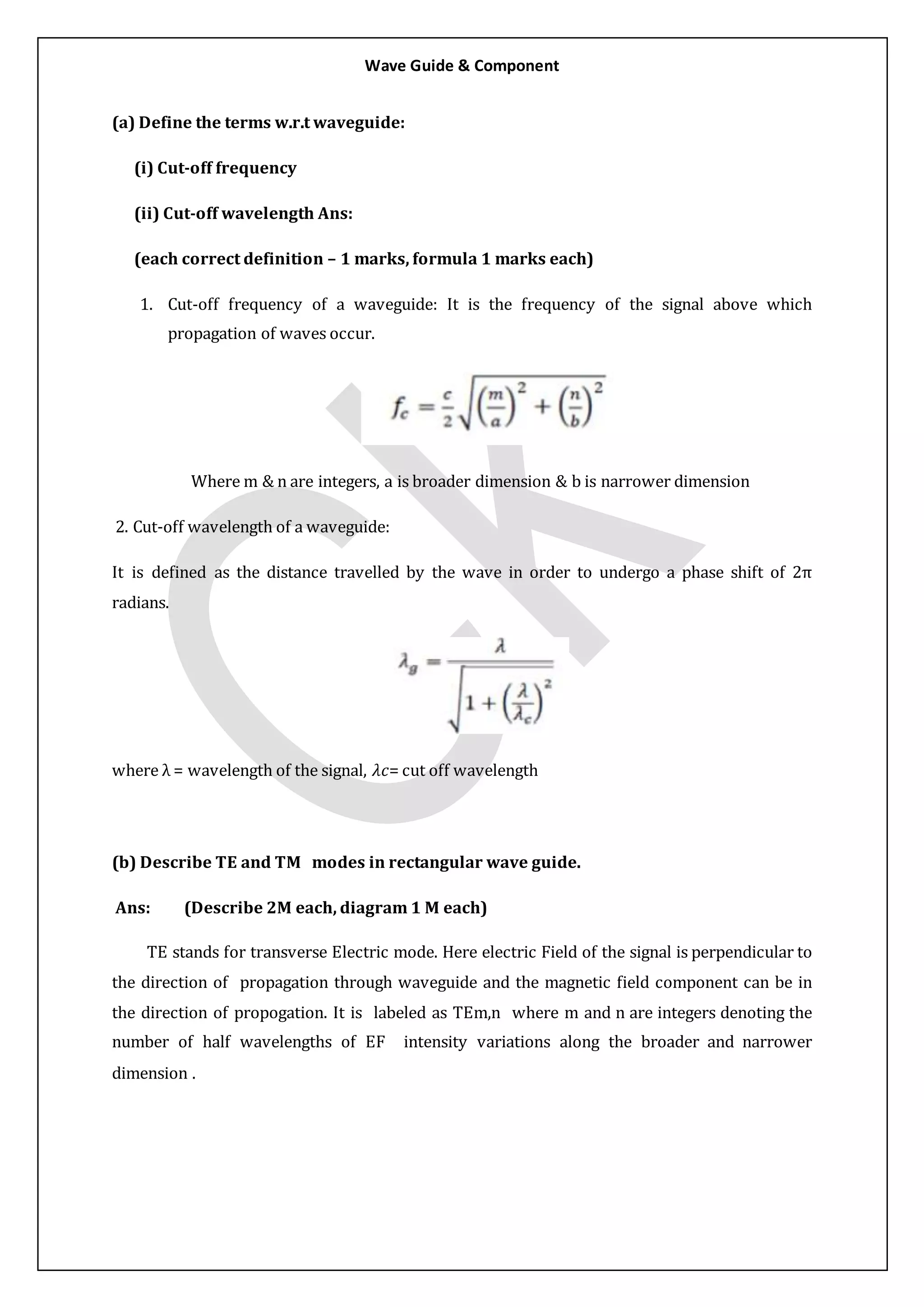
1. Cut-off frequency is the frequency above which waves can propagate through a waveguide. Cut-off wavelength is the wavelength corresponding to the cut-off frequency.
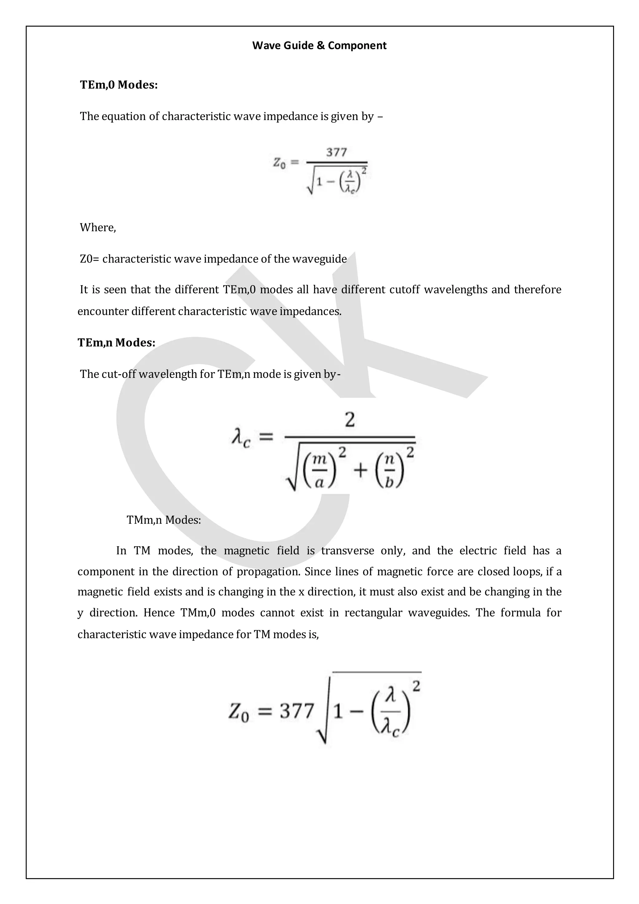
2. TE modes have a transverse electric field and longitudinal magnetic field. TM modes have a transverse magnetic field and longitudinal electric field.
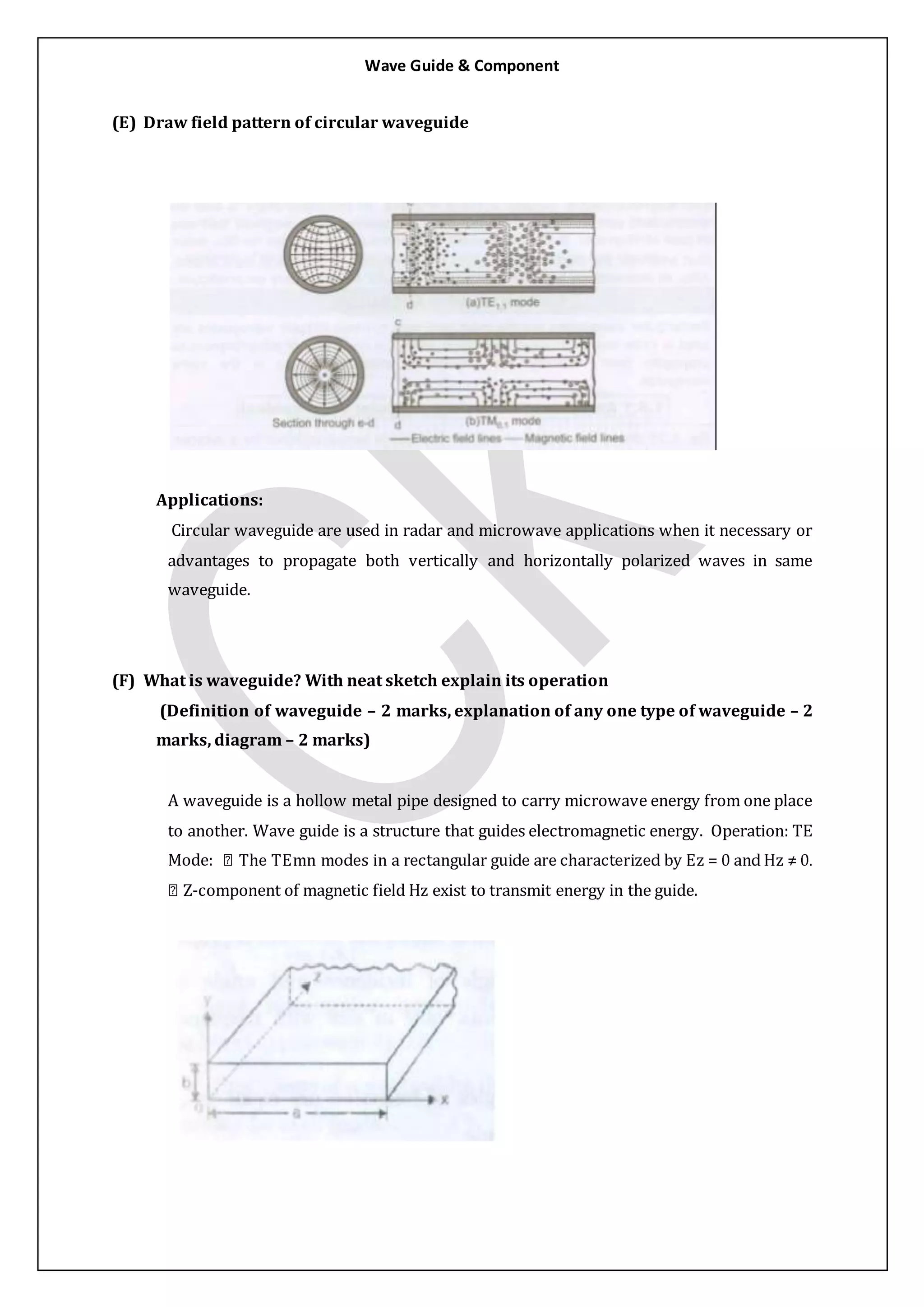
3. Circular waveguides have advantages over rectangular waveguides like being easier to manufacture and join, and allowing propagation of both vertically and horizontally polarized waves. They are used in applications requiring microwave transmission over long distances or high power handling like radar.