Download as PDF, PPTX

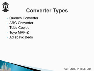
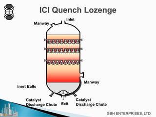
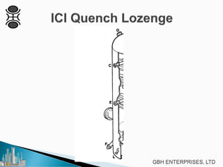
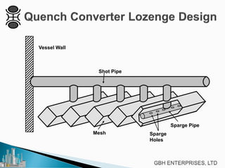
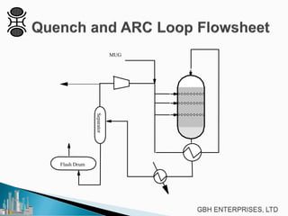
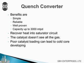
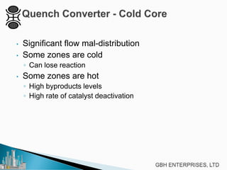
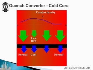
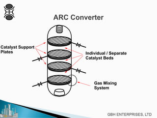
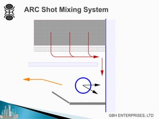
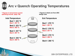
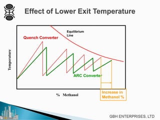
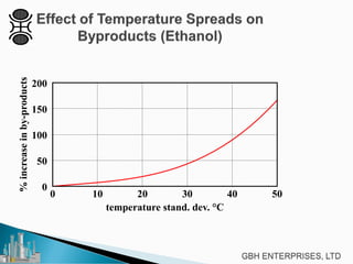
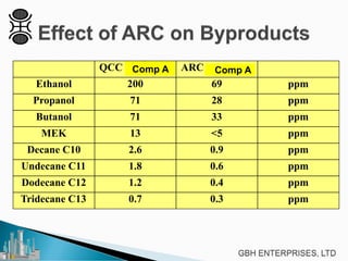
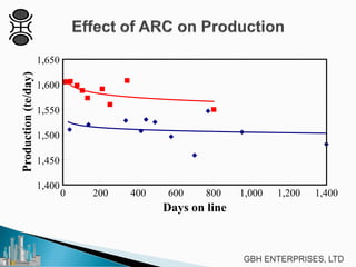
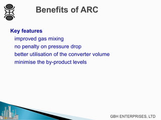
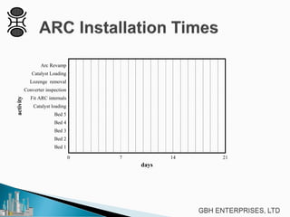
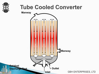
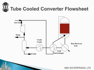
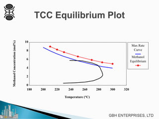
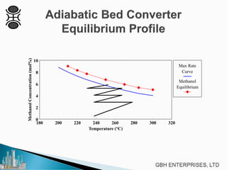


This document discusses different types of methanol synthesis reactors, including quench converters, ARC converters, tube cooled converters, and adiabatic bed reactors. It provides details on the benefits and drawbacks of each type, such as the quench converter being simple and reliable but prone to temperature maldistribution issues across the catalyst beds. The document also examines techniques for improving reactor design and operation, such as the ARC retrofit developed to improve gas mixing in quench converters.


![Kbr[1] report](https://cdn.slidesharecdn.com/ss_thumbnails/kbr1-160104072613-thumbnail.jpg?width=640&height=640&fit=bounds)


