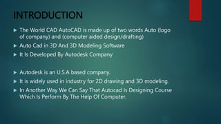
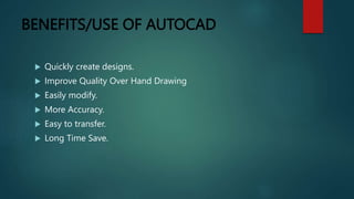
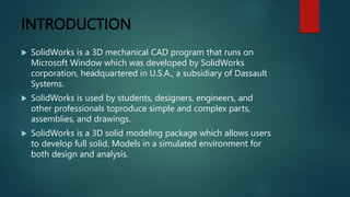
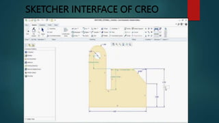
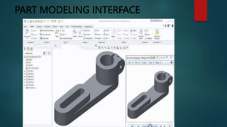
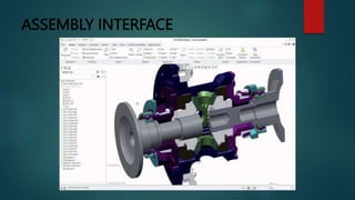
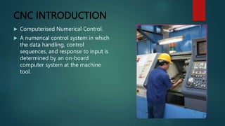
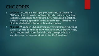
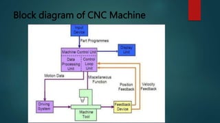
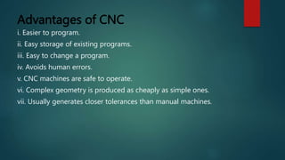
INTERNSHIP AT
INDO GERMAN TOOL ROOM AHMEDABAD
NAME=CHAUHAN DIPAKKUMAR NITINBHAI
EN NO = 210430119566
PMMS TEAM ID = 409300
SEM=8
GUIDE NAME=PROF. P.V.PAREKH SIR
INTRODUCTION
 Since liberalization of the economy established in 1994, India
faces strong international competition. Thus, growth and
diversification of its industry are increasingly characterized by
a shift from simple to technically complex products.
 Many enterprises aim at high value-addition. Modernization
and automation of production processes increase productivity
and reduce unit cost.
 This is particularly true for the engineering industries (metal
and plastics processing ventures) as well as small and
medium-scale enterprises (SME). They manufacture tools and
molds or use them for producing parts, components, systems,
and final products, often as sub-contractors of large
enterprises.
Computer-aided design (CAD)
Definition
Computer-aided design (CAD) is a way to digitally
create 2D drawings and 3D models of real-world
products before they’re ever manufactured.
Software
1. Autocad
2. Solidwork
3. Creo
4. Catia
5. Ansys
INTRODUCTION
 The World CAD AutoCAD is made up of two words Auto (logo
of company) and (computer aided design/drafting)
 Auto Cad in 3D And 3D Modeling Software
 It Is Developed By Autodesk Company
 Autodesk is an U.S.A based company.
 It is widely used in industry for 2D drawing and 3D modeling.
 In Another Way We Can Say That Autocad Is Designing Course
Which Is Perform By The Help Of Computer.
AutoCAD SCREEN
HOW AUTOCAD WORKS
 There is a co-ordinate system used in AutoCAD.
 Every drawing shows its co-ordinate.
 There is so many commands like copy, move,rotate mirror in
2D, path array, rectangular array, polar array & more
 Different types of drawing can be made in the same time by
using a command that is LAYER.
 Using line, arc, circle, rectangle, ellipse & polygon, so many
drawing of different type can be made.
CO-Ordinate System
 AutoCAD provides two types of coordinate systems:
 Work Coordinate System (WCS) is fixed and cannot be
changed. In this system (when viewing the origin from 0,0,1),
the X axis starts at the point 0,0,0, and values increase as the
point moves to the operator’s right; the Y axis starts at 0,0,0,
and values increase as the point moves to the top of the
screen; and finally, the Z axis starts at the 0,0,0 point, and
values get larger as it comes toward the user.
 User Coordinate System (UCS) allows you to change the
location and orientation of the X, Y, and Z axes. The UCS
command lets you redefine the origin of your drawing and
establish the positive X and the positive Y axes.
SOME 2D COMMANDS
2D Drawing
SOME AUTOCAD 2D DRAWING
BENEFITS/USE OF AUTOCAD
 Quickly create designs.
 Improve Quality Over Hand Drawing
 Easily modify.
 More Accuracy.
 Easy to transfer.
 Long Time Save.
SOLID WORK
INTRODUCTION
 SolidWorks is a 3D mechanical CAD program that runs on
Microsoft Window which was developed by SolidWorks
corporation, headquartered in U.S.A., a subsidiary of Dassault
Systems.
 SolidWorks is used by students, designers, engineers, and
other professionals toproduce simple and complex parts,
assemblies, and drawings.
 SolidWorks is a 3D solid modeling package which allows users
to develop full solid. Models in a simulated environment for
both design and analysis.
MODULES IN SOLIDWORKS
1. Part Modelling
2. Assembly Modelling
3. Surface Modelling
4. Drawing
1. Part Modelling:-
 The first, and most basic element of a
SolidWorks model is a Part.
 Parts consist of primitive geometry and
features such as extrudes, revolutions, lofts,
sweeps, etc.
 Parts will be the building blocks for all of the
models that you will create.
 The basic modelling process for each part is
follows:
Plan the part,Create the base feature
Create the remaining features,Analyse the
part,Modify the features as necessary
Uses of some 3D features commands:-
2. Assembly Modelling :-
 Assembly is a combination of two or more
components using parametric relationship.
 In SolidWorks, these relationships is called
mates.
 Mates enable you to control part movement
with respect to each other.
SolidWorks Assembly
3. Surface Modelling :-
 SolidWorks surface module can create complex
surface using loft and sweeps with guide
curves, drag handles for easy control and
innovation surface features.
 The basic process to create the surface model is
as follows:
Acquire the wireframe model.
Study the wireframe model.
Create and verify the required surface.
Output the surface model.
4. Drawing :-
 A drawing is the typical way to represent a
3D model such that any engineer (or
manufacturer) can recreate your part.
 Drawings are important because they
provide a standard way of sharing your
design.
CREO
INTRODUCTION
 Creo parametric software provides every member involved in
the product development process, the right tools needed to
achieve the highest quality design in the fastest possible time.
 Creo parametric is a suite of application you can use to design
products the way you want.
 Creo parametric is the standard in 3D CAD, featuring state-of-
the-art productivity tools that promote best practices in
design while simultaneously ensuring.
 compliance with industrial and company standards.
 With creo, you can create analyze view and share designs.
MODULES OF THE CREO
 Sketcher
 Part Modeling
 1. Solid model
 2. Surface model
 3. Sheet metal model
 Assembly modeling
 Mechanism ,Welding ,Animation
 Drawing ,Format creation
 Template creation ,Simulation
SKETCHER INTERFACE OF CREO
PART MODELING INTERFACE
ASSEMBLY INTERFACE
CNC
CNC INTRODUCTION
 Computerised Numerical Control.
 A numerical control system in which
the data handling, control
sequences, and response to input is
determined by an on-board
computer system at the machine
tool.
HOW CNC WORKS
 Controlled by G and M codes.
 These are number values and co-ordinates.
 Each number or code is assigned to a particular operation.
 Typed in manually to CAD by machine operators.
 G & M codes are automatically generated by the computer
software.
ELEMENTS OF CNC MACHINE
 A CNC machine consist of following 6 major elements:
1. Input Device
2. Machine Control Unit
3. Machine Tool
4. Driving System
5. Feedback Devices
6. Display Unit
COMMON FORMAT OF A BLOCK
CNC CODES
1. G-CODE: G-code is the simple programming language for
CNC machines. It consists of lines of code that are organized
in blocks. Each block controls one CNC machining operation,
such as a cutting operation with a specific tool. Each line in a
block is labeled with the letter N and a number.
2. M-CODE:M-code in CNC machines activates various functions
such as spindle control, coolant management, program stops,
tool changes, and more. Each M-code corresponds to a
specific action or command within the CNC machine.
Block diagram of CNC Machine
OPEN LOOP AND CLOSED LOOP
CONTROLS
 In open loop systems the slide may overshoot or may not reach desired
position because of inertia, wear and tear and friction, hence inaccurate
machining.
 In closed loop systems the position sensors are used to correct slide
movements and achieve higher accuracy and repeatability
Advantages of CNC
i. Easier to program.
ii. Easy storage of existing programs.
iii. Easy to change a program.
iv. Avoids human errors.
v. CNC machines are safe to operate.
vi. Complex geometry is produced as cheaply as simple ones.
vii. Usually generates closer tolerances than manual machines.
THANKS YOU

Power point Presentation on AutoCAD And NX software

  • 1.
    INTERNSHIP AT INDO GERMANTOOL ROOM AHMEDABAD NAME=CHAUHAN DIPAKKUMAR NITINBHAI EN NO = 210430119566 PMMS TEAM ID = 409300 SEM=8 GUIDE NAME=PROF. P.V.PAREKH SIR
  • 2.
    INTRODUCTION  Since liberalizationof the economy established in 1994, India faces strong international competition. Thus, growth and diversification of its industry are increasingly characterized by a shift from simple to technically complex products.  Many enterprises aim at high value-addition. Modernization and automation of production processes increase productivity and reduce unit cost.  This is particularly true for the engineering industries (metal and plastics processing ventures) as well as small and medium-scale enterprises (SME). They manufacture tools and molds or use them for producing parts, components, systems, and final products, often as sub-contractors of large enterprises.
  • 3.
    Computer-aided design (CAD) Definition Computer-aideddesign (CAD) is a way to digitally create 2D drawings and 3D models of real-world products before they’re ever manufactured. Software 1. Autocad 2. Solidwork 3. Creo 4. Catia 5. Ansys
  • 4.
    INTRODUCTION  The WorldCAD AutoCAD is made up of two words Auto (logo of company) and (computer aided design/drafting)  Auto Cad in 3D And 3D Modeling Software  It Is Developed By Autodesk Company  Autodesk is an U.S.A based company.  It is widely used in industry for 2D drawing and 3D modeling.  In Another Way We Can Say That Autocad Is Designing Course Which Is Perform By The Help Of Computer.
  • 5.
  • 6.
    HOW AUTOCAD WORKS There is a co-ordinate system used in AutoCAD.  Every drawing shows its co-ordinate.  There is so many commands like copy, move,rotate mirror in 2D, path array, rectangular array, polar array & more  Different types of drawing can be made in the same time by using a command that is LAYER.  Using line, arc, circle, rectangle, ellipse & polygon, so many drawing of different type can be made.
  • 7.
    CO-Ordinate System  AutoCADprovides two types of coordinate systems:  Work Coordinate System (WCS) is fixed and cannot be changed. In this system (when viewing the origin from 0,0,1), the X axis starts at the point 0,0,0, and values increase as the point moves to the operator’s right; the Y axis starts at 0,0,0, and values increase as the point moves to the top of the screen; and finally, the Z axis starts at the 0,0,0 point, and values get larger as it comes toward the user.  User Coordinate System (UCS) allows you to change the location and orientation of the X, Y, and Z axes. The UCS command lets you redefine the origin of your drawing and establish the positive X and the positive Y axes.
  • 8.
  • 9.
  • 10.
  • 11.
    BENEFITS/USE OF AUTOCAD Quickly create designs.  Improve Quality Over Hand Drawing  Easily modify.  More Accuracy.  Easy to transfer.  Long Time Save.
  • 12.
  • 13.
    INTRODUCTION  SolidWorks isa 3D mechanical CAD program that runs on Microsoft Window which was developed by SolidWorks corporation, headquartered in U.S.A., a subsidiary of Dassault Systems.  SolidWorks is used by students, designers, engineers, and other professionals toproduce simple and complex parts, assemblies, and drawings.  SolidWorks is a 3D solid modeling package which allows users to develop full solid. Models in a simulated environment for both design and analysis.
  • 14.
    MODULES IN SOLIDWORKS 1.Part Modelling 2. Assembly Modelling 3. Surface Modelling 4. Drawing
  • 15.
    1. Part Modelling:- The first, and most basic element of a SolidWorks model is a Part.  Parts consist of primitive geometry and features such as extrudes, revolutions, lofts, sweeps, etc.  Parts will be the building blocks for all of the models that you will create.  The basic modelling process for each part is follows: Plan the part,Create the base feature Create the remaining features,Analyse the part,Modify the features as necessary
  • 16.
    Uses of some3D features commands:-
  • 18.
    2. Assembly Modelling:-  Assembly is a combination of two or more components using parametric relationship.  In SolidWorks, these relationships is called mates.  Mates enable you to control part movement with respect to each other.
  • 19.
  • 20.
    3. Surface Modelling:-  SolidWorks surface module can create complex surface using loft and sweeps with guide curves, drag handles for easy control and innovation surface features.  The basic process to create the surface model is as follows: Acquire the wireframe model. Study the wireframe model. Create and verify the required surface. Output the surface model.
  • 21.
    4. Drawing :- A drawing is the typical way to represent a 3D model such that any engineer (or manufacturer) can recreate your part.  Drawings are important because they provide a standard way of sharing your design.
  • 22.
  • 23.
    INTRODUCTION  Creo parametricsoftware provides every member involved in the product development process, the right tools needed to achieve the highest quality design in the fastest possible time.  Creo parametric is a suite of application you can use to design products the way you want.  Creo parametric is the standard in 3D CAD, featuring state-of- the-art productivity tools that promote best practices in design while simultaneously ensuring.  compliance with industrial and company standards.  With creo, you can create analyze view and share designs.
  • 24.
    MODULES OF THECREO  Sketcher  Part Modeling  1. Solid model  2. Surface model  3. Sheet metal model  Assembly modeling  Mechanism ,Welding ,Animation  Drawing ,Format creation  Template creation ,Simulation
  • 25.
  • 26.
  • 27.
  • 28.
  • 29.
    CNC INTRODUCTION  ComputerisedNumerical Control.  A numerical control system in which the data handling, control sequences, and response to input is determined by an on-board computer system at the machine tool.
  • 30.
    HOW CNC WORKS Controlled by G and M codes.  These are number values and co-ordinates.  Each number or code is assigned to a particular operation.  Typed in manually to CAD by machine operators.  G & M codes are automatically generated by the computer software.
  • 31.
    ELEMENTS OF CNCMACHINE  A CNC machine consist of following 6 major elements: 1. Input Device 2. Machine Control Unit 3. Machine Tool 4. Driving System 5. Feedback Devices 6. Display Unit
  • 32.
  • 33.
    CNC CODES 1. G-CODE:G-code is the simple programming language for CNC machines. It consists of lines of code that are organized in blocks. Each block controls one CNC machining operation, such as a cutting operation with a specific tool. Each line in a block is labeled with the letter N and a number. 2. M-CODE:M-code in CNC machines activates various functions such as spindle control, coolant management, program stops, tool changes, and more. Each M-code corresponds to a specific action or command within the CNC machine.
  • 34.
    Block diagram ofCNC Machine
  • 35.
    OPEN LOOP ANDCLOSED LOOP CONTROLS  In open loop systems the slide may overshoot or may not reach desired position because of inertia, wear and tear and friction, hence inaccurate machining.  In closed loop systems the position sensors are used to correct slide movements and achieve higher accuracy and repeatability
  • 36.
    Advantages of CNC i.Easier to program. ii. Easy storage of existing programs. iii. Easy to change a program. iv. Avoids human errors. v. CNC machines are safe to operate. vi. Complex geometry is produced as cheaply as simple ones. vii. Usually generates closer tolerances than manual machines.
  • 37.