V-I characteristics of Zener Diode
•Download as DOCX, PDF•
1 like•2,939 views

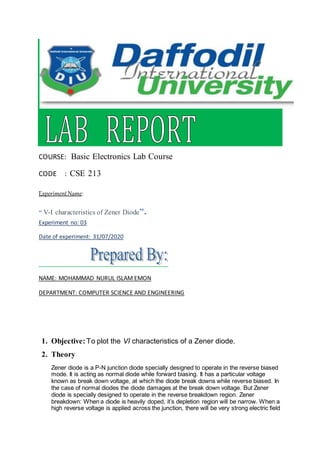
This experiment was conducted to plot the V-I characteristics of a Zener diode. Key equipment used includes a Zener diode, DC voltage supplier, breadboard, 100Ω resistor, and connecting wires. Tables of data collected show forward and reverse bias voltages with the corresponding currents. The graph produced has forward voltage on the positive x-axis and reverse voltage on the negative x-axis, with forward current on the positive y-axis and reverse current on the negative y-axis. In forward bias, the Zener diode behaves like a standard diode, while in reverse bias there is a small leakage current until the breakdown voltage is reached, at which point maximum current flows through the Zener diode.
Report
Share
Report
Share

Recommended
Lab - 03
This document summarizes an experiment on diode clipping and clamping circuits. It includes the objectives, equipment used, circuit diagrams of clipping and clamping circuits tested, and results from those circuits. Key findings are: 1) clipping circuits cut off portions of the input signal above or below certain voltage thresholds, while clamping circuits shift the entire signal up or down by a fixed amount. 2) In a clipping circuit, diodes allow the output to follow the input until a threshold is reached, then clamp the output at that level. 3) A clamping circuit uses a capacitor, diode, and resistor to shift the entire signal down by twice the peak input voltage.
Zener diode as a voltage Regulator
The document discusses the use of Zener diodes as voltage regulators. It begins by describing how Zener diodes allow current to flow in the reverse direction above a certain breakdown voltage. It then discusses different types of Zener diodes categorized by voltage, current, and power ratings. The document explains that Zener diodes can regulate an unsteady input voltage to provide a steady output voltage. It provides an example circuit diagram of a Zener diode regulating a 12V supply down to a steady 8V for a 100mA load. Measurements and component selections are described to illustrate how the Zener diode maintains a constant voltage across varying loads and minor input fluctuations.
Cro (emmi) (1)
This document discusses the cathode-ray oscilloscope (CRO), which is a versatile instrument used to observe and analyze waveforms by plotting amplitude over time. It describes the key components of a CRO, including the cathode-ray tube, vertical and horizontal amplifiers, time-base generator, and triggering circuit. The document provides details on how these components work together to display input signals on the CRT screen and enable measurements of amplitude, frequency, and phase. It also discusses some applications of CROs and covers topics like time-base generators, oscilloscope amplifiers, and the frequency response of CROs.
Water level indicator
This document presents a water level indicator circuit that uses three transistors and LEDs to indicate the water level in a tank. As the water level rises, it makes contact with the transistor bases at different heights, causing the corresponding LEDs to light up. When the water reaches the highest level and activates the third transistor, a buzzer will sound to indicate that the tank is full. The circuit uses inexpensive and easily available components like transistors, LEDs, resistors, and a buzzer. It provides a low-cost solution to monitor water levels and prevent overfilling without consuming much power.
Zener diode as voltage regulator
This document outlines an experiment to understand how a zener diode can be used as a voltage regulator. It describes how zener diodes have a high doping level that allows them to maintain a constant voltage under reverse bias. The circuit uses a zener diode, resistors, potentiometer and battery to regulate the voltage. By varying the potentiometer, the voltage drop across the zener diode remains constant at its breakdown voltage. Voltage regulators are important in electronics to provide a steady voltage for circuits.
Pn junction diode characteristics Lab expriment
This document describes the characteristics of a PN junction diode. It defines a PN junction as where a P-type semiconductor is joined to an N-type semiconductor. In forward bias, current is constant until the cut-in voltage is reached, after which it conducts. In reverse bias, current is small until the breakdown voltage is reached. The objectives are to plot the volt-ampere characteristics, find the cut-in voltage, and determine static and dynamic resistances in forward and reverse bias. The activity involves connecting a diode in a circuit and taking voltage and current readings in forward and reverse bias to generate the VI characteristics graph and calculate resistances.
Field Effect Transistor
FET are :
Voltage controlled devices
Higher input impedance
Less sensitive to temp. variations
Unipolar device
Smaller/ Easily Integrated Chips
Verification of Thevenin’s Theorem. lab report
1) The document describes an experiment to verify Thevenin's theorem, which states that a linear two-terminal circuit can be represented by an equivalent circuit with a voltage source Vth and resistor Rth.
2) The experiment used a DC power supply, resistors, wires, a voltmeter, and ammeter to construct the circuit and measure voltages and currents.
3) Calculations showed that Vth = 3.4V, Rth = 113Ω, Io = 10mA, IL' = 10.2mA with an error of 1.96% between the actual and equivalent currents, verifying Thevenin's theorem.
Water level indicator
A water detector is an electronicdevice that is designed to detect the presence of water and provide an alert in time to allow the prevention of water damage.
Single stage bjt amplifier. experiment 6
This document describes the theory and experimental procedure of a single stage BJT amplifier. It discusses the three common configurations of BJT amplifiers: common emitter, common base, and common collector. The experiment aims to differentiate the configurations, measure DC and AC parameters, and observe the voltage gain differences between common emitter and common collector circuits. Key results showed the common emitter configuration amplified the signal as expected, while the common collector configuration did not amplify and had a voltage gain close to unity.
3 nodal analysis
The document discusses the steps of nodal analysis which includes choosing a reference node, assigning voltages to nodes, applying Kirchhoff's Current Law (KCL) at each node to obtain equations relating currents and voltages, and solving the system of equations to determine node voltages. An example circuit is presented and nodal analysis is performed on it by defining node voltages, writing KCL equations, and solving to find the output voltage. Nodal analysis is a technique for analyzing electrical circuits by writing equations at nodes based on KCL.
Electronics 1 : Chapter # 05 : DC Biasing BJT
Electronics 1 complete course plus guide. For complete course and more visit our website https://www.swebllc.com/?cat=12
Diode Application
Diode applications can be configured in series or parallel circuits. In series configurations, the diode resistance is small compared to other elements when forward biased, and has high resistance when reverse biased. Parallel and series-parallel configurations determine network resistances. Half-wave rectification only passes one half of the AC cycle. Peak inverse voltage must exceed the peak AC voltage to prevent reverse breakdown. Clippers and clampers use diodes to modify input signals without distortion.
BJT, FET, MOSFET as Switch
The document discusses how bipolar junction transistors (BJTs) and field effect transistors (FETs) can be used as switches. It provides examples of using NPN and PNP BJTs as switches by biasing them into saturation or cutoff regions. FETs like JFETs and MOSFETs can also be used as switches by operating them in saturation, cutoff, or ohmic regions depending on the gate-source voltage. Circuits are presented showing BJTs and FETs controlling loads like lamps and LEDs by acting as open or closed switches. The document explains how small control signals can turn transistors on to handle much larger load currents.
TOWNSEND'S CURRENT GROWTH EQUATION DERIVATION IN HINDI|TOWNSEND'S THEORY|HIGH...
This document discusses John Sealy Townsend's theories on breakdown in gases and his current growth equation. Townsend studied the process of ionization where an electron liberates an atom, forming a positive ion and two electrons. He found that current first increases proportionally with voltage, then remains constant, and finally increases exponentially at higher voltages due to electron collision ionization of gas. Townsend's current growth equation models how the number of electrons increases exponentially based on the number of ionizing collisions per unit distance, represented by Townsend's first ionization coefficient, and the distance from the cathode.
Different types of interconnection of two port networks
This document discusses different ways that two-port networks can be interconnected: in parallel, in series, and in cascade. It provides the mathematical equations for calculating the overall network parameters (Y, Z, and ABCD parameters) when two networks are connected in series, parallel or cascade configurations. The document includes references to textbooks and publications on microwave engineering and RF circuit design for further reading.
Zener Diode-As Voltage Regulator
On this presentation describe all the detail of zener diode. And also describe the working as voltage regulator.
Rectifier and Filter circuits (chapter14)
The three types of rectifiers in just 18 slides. Learn and enjoy the concepts. This PowerPoint presentation not only tells about the working and principles of rectifiers but also determines the disadvantages and advantages of different rectifiers. This PowerPoint presentation also has circuit diagrams that suit your necessities. This PPT can be written as an answer for a long type of question too.
Zenerdiode lab report
This document outlines an experiment to study the characteristics and voltage regulation properties of a Zener diode. The experiment involves constructing circuits using a 10V Zener diode and measuring voltages and currents across the diode and various resistors as the supply voltage is varied. Key characteristics of the Zener diode such as reverse breakdown voltage and operation as a voltage regulator are examined.
Half wave Rectifier & Full wave Rectifier with their descriptions.
This document summarizes half wave and full wave rectifiers. It describes that a rectifier converts alternating current (AC) to direct current (DC) through a process called rectification. There are two main types - half wave and full wave rectifiers. A half wave rectifier only conducts during the positive half cycle of the input AC signal, while a full wave rectifier conducts during both half cycles using two diodes or a diode bridge. Full wave rectifiers have higher efficiency and output than half wave rectifiers but require more diodes. The document provides circuit diagrams and explanations of operation for both half wave and full wave rectifier configurations.
L11 rc triggering circuit
Part of Lecture series on EE321N, Power Electronics-I delivered by me during Fifth Semester of B.Tech. Electrical Engg., 2012
Z H College of Engg. & Technology, Aligarh Muslim University, Aligarh
Please comment and feel free to ask anything related. Thanks!
Initial and final condition for circuit
Initial and final condition for circuit
Explain the transient response of a RC circuit
As the capacitor stores energy when there is:
a transition in a unit step function source, u(t-to)
or a voltage or current source is switched into the circuit.
Explain the transient response of a RL circuit
As the inductor stores energy when there is:
a transition in a unit step function source, u(t-to)
or a voltage or current source is switched into the circuit.
RC Circuit
RL Circuit
Large signal vs small signal
1. Large-signal analysis finds the operating point or bias conditions of a circuit by using device equations and KVL/KCL. Small-signal analysis linearizes the circuit around this operating point to find parameters like gain.
2. Small-signal analysis involves adding a small AC signal to tweak the operating point. Near the operating point, non-linear devices can be approximated as linear to analyze the circuit response.
3. The small-signal model is constructed using parameters derived from the large-signal operating point and used to analyze quantities like gain and resistances.
Tunnel Diode
Tunnel Diode- Introduction, Definition, Circuit diagram, Process, VI characteristics, advantages, Disadvantages and Application
Module3: opamp as a Schmitt trigger
The document discusses operational amplifiers and Schmitt triggers. It defines a Schmitt trigger as a comparator that uses positive feedback, giving it distinct upper and lower threshold voltages. The document describes the inverting and non-inverting configurations of Schmitt triggers and provides mathematical expressions for calculating the threshold voltages. It compares the characteristics of comparators and Schmitt triggers, noting that Schmitt triggers can convert waveforms to square waves using positive feedback. The document was presented by an electrical engineering professor to explain operational amplifier applications.
Mesh Analysis.pptx
Mesh analysis is a technique for analyzing electrical circuits by applying Kirchhoff's voltage law around loops of meshes. It reduces the number of equations needed to the number of meshes. The steps are to identify meshes, assign currents to each mesh, apply KVL to each mesh to generate equations, and solve the system of linear equations. Supermeshes can form when two meshes share a common current source, in which case that branch is removed.
Tellegen's theorem
This document discusses Tellegen's theorem of circuit theory. It states that at any time t, the algebraic sum of the instantaneous power in n branches of a network equals zero if Kirchhoff's current law (KCL) and Kirchhoff's voltage law (KVL) are satisfied. The document provides the mathematical statement of the theorem and proves it using a sample circuit where KCL and KVL are verified and the power in each branch is calculated to show that the total power supplied equals the total power dissipated.
Zener diode
The document discusses Zener diodes, which are designed to operate reliably in reverse breakdown. Zener diodes have a sharp, well-defined breakdown voltage determined by the doping concentration. There are two types of breakdown mechanisms - Zener breakdown for heavily doped PN junctions and avalanche breakdown for lightly doped junctions. Zener diodes can be used as voltage regulators since their breakdown voltage remains constant, allowing the output voltage to remain stable despite input voltage or load variations by maintaining the current through the Zener. The value of the series resistor in a Zener regulator circuit is calculated based on the input and Zener voltages and the total current.
207137236 ee2207-lm
homework help,online homework help,online tutors,online tutoring,research paper help,do my homework,
https://www.homeworkping.com/
227 sample chapter
The document discusses semiconductor diodes and their applications. It explains how a p-n junction is formed and the barrier potential that is set up. It describes the forward and reverse biasing of diodes and how this affects conduction. The voltage-current characteristics of ideal diodes and real diodes are examined. Applications of diodes include rectification, clipping, and clamping in circuits. Half-wave and full-wave rectifier circuits are explained.
More Related Content
What's hot
Water level indicator
A water detector is an electronicdevice that is designed to detect the presence of water and provide an alert in time to allow the prevention of water damage.
Single stage bjt amplifier. experiment 6
This document describes the theory and experimental procedure of a single stage BJT amplifier. It discusses the three common configurations of BJT amplifiers: common emitter, common base, and common collector. The experiment aims to differentiate the configurations, measure DC and AC parameters, and observe the voltage gain differences between common emitter and common collector circuits. Key results showed the common emitter configuration amplified the signal as expected, while the common collector configuration did not amplify and had a voltage gain close to unity.
3 nodal analysis
The document discusses the steps of nodal analysis which includes choosing a reference node, assigning voltages to nodes, applying Kirchhoff's Current Law (KCL) at each node to obtain equations relating currents and voltages, and solving the system of equations to determine node voltages. An example circuit is presented and nodal analysis is performed on it by defining node voltages, writing KCL equations, and solving to find the output voltage. Nodal analysis is a technique for analyzing electrical circuits by writing equations at nodes based on KCL.
Electronics 1 : Chapter # 05 : DC Biasing BJT
Electronics 1 complete course plus guide. For complete course and more visit our website https://www.swebllc.com/?cat=12
Diode Application
Diode applications can be configured in series or parallel circuits. In series configurations, the diode resistance is small compared to other elements when forward biased, and has high resistance when reverse biased. Parallel and series-parallel configurations determine network resistances. Half-wave rectification only passes one half of the AC cycle. Peak inverse voltage must exceed the peak AC voltage to prevent reverse breakdown. Clippers and clampers use diodes to modify input signals without distortion.
BJT, FET, MOSFET as Switch
The document discusses how bipolar junction transistors (BJTs) and field effect transistors (FETs) can be used as switches. It provides examples of using NPN and PNP BJTs as switches by biasing them into saturation or cutoff regions. FETs like JFETs and MOSFETs can also be used as switches by operating them in saturation, cutoff, or ohmic regions depending on the gate-source voltage. Circuits are presented showing BJTs and FETs controlling loads like lamps and LEDs by acting as open or closed switches. The document explains how small control signals can turn transistors on to handle much larger load currents.
TOWNSEND'S CURRENT GROWTH EQUATION DERIVATION IN HINDI|TOWNSEND'S THEORY|HIGH...
This document discusses John Sealy Townsend's theories on breakdown in gases and his current growth equation. Townsend studied the process of ionization where an electron liberates an atom, forming a positive ion and two electrons. He found that current first increases proportionally with voltage, then remains constant, and finally increases exponentially at higher voltages due to electron collision ionization of gas. Townsend's current growth equation models how the number of electrons increases exponentially based on the number of ionizing collisions per unit distance, represented by Townsend's first ionization coefficient, and the distance from the cathode.
Different types of interconnection of two port networks
This document discusses different ways that two-port networks can be interconnected: in parallel, in series, and in cascade. It provides the mathematical equations for calculating the overall network parameters (Y, Z, and ABCD parameters) when two networks are connected in series, parallel or cascade configurations. The document includes references to textbooks and publications on microwave engineering and RF circuit design for further reading.
Zener Diode-As Voltage Regulator
On this presentation describe all the detail of zener diode. And also describe the working as voltage regulator.
Rectifier and Filter circuits (chapter14)
The three types of rectifiers in just 18 slides. Learn and enjoy the concepts. This PowerPoint presentation not only tells about the working and principles of rectifiers but also determines the disadvantages and advantages of different rectifiers. This PowerPoint presentation also has circuit diagrams that suit your necessities. This PPT can be written as an answer for a long type of question too.
Zenerdiode lab report
This document outlines an experiment to study the characteristics and voltage regulation properties of a Zener diode. The experiment involves constructing circuits using a 10V Zener diode and measuring voltages and currents across the diode and various resistors as the supply voltage is varied. Key characteristics of the Zener diode such as reverse breakdown voltage and operation as a voltage regulator are examined.
Half wave Rectifier & Full wave Rectifier with their descriptions.
This document summarizes half wave and full wave rectifiers. It describes that a rectifier converts alternating current (AC) to direct current (DC) through a process called rectification. There are two main types - half wave and full wave rectifiers. A half wave rectifier only conducts during the positive half cycle of the input AC signal, while a full wave rectifier conducts during both half cycles using two diodes or a diode bridge. Full wave rectifiers have higher efficiency and output than half wave rectifiers but require more diodes. The document provides circuit diagrams and explanations of operation for both half wave and full wave rectifier configurations.
L11 rc triggering circuit
Part of Lecture series on EE321N, Power Electronics-I delivered by me during Fifth Semester of B.Tech. Electrical Engg., 2012
Z H College of Engg. & Technology, Aligarh Muslim University, Aligarh
Please comment and feel free to ask anything related. Thanks!
Initial and final condition for circuit
Initial and final condition for circuit
Explain the transient response of a RC circuit
As the capacitor stores energy when there is:
a transition in a unit step function source, u(t-to)
or a voltage or current source is switched into the circuit.
Explain the transient response of a RL circuit
As the inductor stores energy when there is:
a transition in a unit step function source, u(t-to)
or a voltage or current source is switched into the circuit.
RC Circuit
RL Circuit
Large signal vs small signal
1. Large-signal analysis finds the operating point or bias conditions of a circuit by using device equations and KVL/KCL. Small-signal analysis linearizes the circuit around this operating point to find parameters like gain.
2. Small-signal analysis involves adding a small AC signal to tweak the operating point. Near the operating point, non-linear devices can be approximated as linear to analyze the circuit response.
3. The small-signal model is constructed using parameters derived from the large-signal operating point and used to analyze quantities like gain and resistances.
Tunnel Diode
Tunnel Diode- Introduction, Definition, Circuit diagram, Process, VI characteristics, advantages, Disadvantages and Application
Module3: opamp as a Schmitt trigger
The document discusses operational amplifiers and Schmitt triggers. It defines a Schmitt trigger as a comparator that uses positive feedback, giving it distinct upper and lower threshold voltages. The document describes the inverting and non-inverting configurations of Schmitt triggers and provides mathematical expressions for calculating the threshold voltages. It compares the characteristics of comparators and Schmitt triggers, noting that Schmitt triggers can convert waveforms to square waves using positive feedback. The document was presented by an electrical engineering professor to explain operational amplifier applications.
Mesh Analysis.pptx
Mesh analysis is a technique for analyzing electrical circuits by applying Kirchhoff's voltage law around loops of meshes. It reduces the number of equations needed to the number of meshes. The steps are to identify meshes, assign currents to each mesh, apply KVL to each mesh to generate equations, and solve the system of linear equations. Supermeshes can form when two meshes share a common current source, in which case that branch is removed.
Tellegen's theorem
This document discusses Tellegen's theorem of circuit theory. It states that at any time t, the algebraic sum of the instantaneous power in n branches of a network equals zero if Kirchhoff's current law (KCL) and Kirchhoff's voltage law (KVL) are satisfied. The document provides the mathematical statement of the theorem and proves it using a sample circuit where KCL and KVL are verified and the power in each branch is calculated to show that the total power supplied equals the total power dissipated.
Zener diode
The document discusses Zener diodes, which are designed to operate reliably in reverse breakdown. Zener diodes have a sharp, well-defined breakdown voltage determined by the doping concentration. There are two types of breakdown mechanisms - Zener breakdown for heavily doped PN junctions and avalanche breakdown for lightly doped junctions. Zener diodes can be used as voltage regulators since their breakdown voltage remains constant, allowing the output voltage to remain stable despite input voltage or load variations by maintaining the current through the Zener. The value of the series resistor in a Zener regulator circuit is calculated based on the input and Zener voltages and the total current.
What's hot (20)
TOWNSEND'S CURRENT GROWTH EQUATION DERIVATION IN HINDI|TOWNSEND'S THEORY|HIGH...
TOWNSEND'S CURRENT GROWTH EQUATION DERIVATION IN HINDI|TOWNSEND'S THEORY|HIGH...
Different types of interconnection of two port networks
Different types of interconnection of two port networks
Half wave Rectifier & Full wave Rectifier with their descriptions.
Half wave Rectifier & Full wave Rectifier with their descriptions.
Similar to V-I characteristics of Zener Diode
207137236 ee2207-lm
homework help,online homework help,online tutors,online tutoring,research paper help,do my homework,
https://www.homeworkping.com/
227 sample chapter
The document discusses semiconductor diodes and their applications. It explains how a p-n junction is formed and the barrier potential that is set up. It describes the forward and reverse biasing of diodes and how this affects conduction. The voltage-current characteristics of ideal diodes and real diodes are examined. Applications of diodes include rectification, clipping, and clamping in circuits. Half-wave and full-wave rectifier circuits are explained.
EDC LAB MASTER MANUAL AY 22-23.doc
This document describes experiments to be performed in an electronic devices and circuits lab. It includes 12 experiments involving diodes, transistors, rectifiers, and other electronic components. The first experiment listed is to characterize a PN junction diode by measuring its forward and reverse bias voltage-current characteristics and calculating values like cut-in voltage and resistance. The second experiment involves obtaining characteristics and determining the zener breakdown voltage of a zener diode, as well as using a zener diode as a voltage regulator. The third experiment measures the performance of a full-wave rectifier both with and without a filter capacitor, determining values like ripple factor and regulation percentage.
Zener diode experiment.
The Zener diode is fabricated in such a way that, its advantage is in its reverse bios. After a sufficient increase in reverse voltage across the junction, the minority carriers get sufficient kinetic energy due to the strong electric field. The high kinetic energy free electrons can collide strongly with the lattice ions so that they emit more free electrons, these liberated electrons also get high kinetic energy due to reverse applied electric field and they create more free electrons by collision cumulatively. This process may continue repeatedly and soon large free electron gas is created in the depletion layer, at which a small change in potential creates huge recombination and surge of carriers across the junction and hence large current through the circuit spontaneously and hence the entire diode will become conductive.
Zener diode is an important electronic device mainly used as voltage regulator. The experiment explains the determination of zener voltage and resistance of diode.
I-v charateristics of zener diode
This document discusses Zener diodes. It begins by explaining that a Zener diode allows current to flow in both the forward and reverse directions, unlike a normal diode. It then provides the symbol for a Zener diode and explains how it operates in forward and reverse bias. The document notes that Zener diodes are commonly used to regulate voltage in circuits by maintaining a constant voltage regardless of changes in current or supply voltage. It concludes by listing some common applications of Zener diodes, such as in voltage stabilizers, over voltage protection circuits, and as reference elements.
Eg1108 rectifiers
The document discusses diode rectifiers and power supplies. It describes how diodes allow current to flow in only one direction, and how this property is exploited in rectifier circuits to convert alternating current (AC) to direct current (DC). Specifically, it examines the half-wave rectifier circuit, which uses a single diode to rectify the positive half of the AC waveform. The output of the half-wave rectifier is pulsed DC with a large ripple. Power supplies often use rectifier circuits to convert high voltage AC mains electricity to a lower voltage DC for electronic circuits.
Zener Diode Presentation
This presentation summarizes the Zener diode. It begins by defining a diode and introducing the Zener diode, which was invented by Clarence Zener and allows current to flow in reverse bias above the Zener voltage. It then discusses the construction and depletion region of the Zener diode. The presentation covers the key features and graphical representation of current-voltage characteristics. It concludes by outlining several applications of Zener diodes in voltage regulation, waveform clipping, voltage shifting, surge protection, and random number generation.
EDC.pdf
This document describes experiments on diode characteristics and applications. Experiment 1 involves identifying diode terminals and measuring the current-voltage characteristics of silicon and germanium diodes. Experiment 2 examines half-wave rectifier circuits and the effect of capacitors. Experiment 3 analyzes full-wave rectifier circuits with center tap and their voltage waveforms. Later experiments cover zener diode characteristics, clipper circuits, and clamper circuits. Diode switching is used to clip signal waveforms in various ways.
Chapter2
Electrical current, voltage, resistance, capacitance, and inductance are a few of the basic elements of electronics and radio. Apart from current, voltage, resistance, capacitance, and inductance, there are many other interesting elements to electronic technology. ... Use Electronics Notes to learn electronics online.
Physics Investigatory:To Study V-I Characteristics Of Zener Diode
This File Covers The Topic Of Zener Diode To Study It's V-I Characteristics and Reverse breakdown Voltage by Performing an experiment
Bee Electronic microproject Roll No.41 to 44.pptx
1. The report discusses the working of a Zener diode and how it can be used as a voltage regulator. It explains that a Zener diode allows current to flow in the reverse direction when the Zener voltage is reached.
2. The report includes the symbol of a Zener diode and provides a circuit diagram showing how a Zener diode can regulate voltage. It explains that the voltage across a Zener diode remains constant over a range of currents.
3. Resources on Zener diodes and voltage regulators are cited at the end to provide additional information on the topic.
Electrical and Electronics Engineering
Electrical Engineering is the Branch of Engineering. Electrical Engineering field requires an understanding of core areas including Thermal and Hydraulics Prime Movers, Analog Electronic Circuits, Network Analysis and Synthesis, DC Machines and Transformers, Digital Electronic Circuits, Fundamentals of Power Electronics, Control System Engineering, Engineering Electromagnetics, Microprocessor and Microcontroller. Ekeeda offers Online Mechanical Engineering Courses for all the Subjects as per the Syllabus. Visit : https://ekeeda.com/streamdetails/stream/Electrical-and-Electronics-Engineering
Diodes and semiconductors - an introduction
It's a description of diodes and semiconductors. It has the information about they work in the circuitry and how they are used in the industry.
Electronics power supplies
1. Power supplies convert the 240V AC mains supply into suitable DC voltages between 5-30V for electronic equipment through transformers, rectifiers, and regulators.
2. Transformers convert the AC voltage to a lower isolated AC voltage, which is then rectified to DC and smoothed by capacitors.
3. Various rectifier circuits like half-wave, full-wave, and bridge are used to rectify different portions of the AC cycle. Smoothing circuits use large capacitors to reduce ripple in the DC output.
4. Regulator circuits like zener diodes and integrated circuits are used to stabilize the output DC voltage against fluctuations in the input voltage and load. Heat sinks are required to dissip
Semiconductor diodes
Semiconductor
If a valence Electron acquires sufficient kinetic energy to break its covalent bond and fills the void created by a hole then a vacancy, or hole will be created in the covalent bond that released the electron
Hence there is a transfer of holes to the left and electrons to the right
EGRE 224 - Microelectronics
The document describes five diode circuit designs: a half-wave rectifier, peak rectifier, negative DC restorer, voltage doubler, and voltage tripler. It provides theoretical background on how each circuit works, including diagrams of the circuit schematics and example waveforms. Equations are presented showing the relationships between voltage and current in the circuits. The purpose of the lab is to physically implement these five circuits using diodes, resistors, and capacitors and compare the results to theoretical predictions.
Basic electronics (p-n Junction)
A p-n junction diode allows current to flow easily in one direction, but blocks it in the other. It is made up of p-type and n-type semiconductor material. In forward bias, current flows when the positive terminal is connected to the p-side and negative to the n-side. In reverse bias, little to no current flows when the connections are reversed. An ideal diode model approximates the diode as having zero resistance in forward bias and infinite resistance in reverse bias.
Three phase shifter appliance
The document is a report on the design of a three phase shifter appliance. It includes chapters introducing the project and describing the need for automation in power systems. It lists the components used in the circuit diagram, including operational amplifiers, transistors, relays, zener diodes and other electrical components. The block diagram and circuit diagram are presented and key components like the comparator, zener diode, and p-n junction are described in detail.
Diode Applications & Transistor Basics
1. The document discusses the V-I characteristics of a p-n junction diode and describes its behavior under zero external voltage, forward bias, and reverse bias.
2. Rectifiers are introduced as circuits that convert AC to DC. Half-wave and full-wave rectifiers are described, including their circuit arrangements and operations. Centre-tap and bridge configurations are covered for full-wave rectification.
3. Zener diodes are discussed as properly doped diodes with a sharp breakdown voltage. They are always connected in reverse bias and have a defined zener voltage.
Microelectronic circuits and devices: chapter one
This document discusses diode models and characteristics. It introduces the ideal diode model and its voltage-current relationship. It then discusses more realistic models that account for the diode's finite voltage drop of around 0.7V. The document explains how to determine the diode constants like the emission coefficient and leakage current by analyzing voltage-current curves. It also discusses how temperature affects the diode's leakage current and voltage characteristics.
Similar to V-I characteristics of Zener Diode (20)
Physics Investigatory:To Study V-I Characteristics Of Zener Diode
Physics Investigatory:To Study V-I Characteristics Of Zener Diode
Recently uploaded
原版制作(unimelb毕业证书)墨尔本大学毕业证Offer一模一样
学校原件一模一样【微信:741003700 】《(unimelb毕业证书)墨尔本大学毕业证》【微信:741003700 】学位证,留信认证(真实可查,永久存档)原件一模一样纸张工艺/offer、雅思、外壳等材料/诚信可靠,可直接看成品样本,帮您解决无法毕业带来的各种难题!外壳,原版制作,诚信可靠,可直接看成品样本。行业标杆!精益求精,诚心合作,真诚制作!多年品质 ,按需精细制作,24小时接单,全套进口原装设备。十五年致力于帮助留学生解决难题,包您满意。
本公司拥有海外各大学样板无数,能完美还原。
1:1完美还原海外各大学毕业材料上的工艺:水印,阴影底纹,钢印LOGO烫金烫银,LOGO烫金烫银复合重叠。文字图案浮雕、激光镭射、紫外荧光、温感、复印防伪等防伪工艺。材料咨询办理、认证咨询办理请加学历顾问Q/微741003700
【主营项目】
一.毕业证【q微741003700】成绩单、使馆认证、教育部认证、雅思托福成绩单、学生卡等!
二.真实使馆公证(即留学回国人员证明,不成功不收费)
三.真实教育部学历学位认证(教育部存档!教育部留服网站永久可查)
四.办理各国各大学文凭(一对一专业服务,可全程监控跟踪进度)
如果您处于以下几种情况:
◇在校期间,因各种原因未能顺利毕业……拿不到官方毕业证【q/微741003700】
◇面对父母的压力,希望尽快拿到;
◇不清楚认证流程以及材料该如何准备;
◇回国时间很长,忘记办理;
◇回国马上就要找工作,办给用人单位看;
◇企事业单位必须要求办理的
◇需要报考公务员、购买免税车、落转户口
◇申请留学生创业基金
留信网认证的作用:
1:该专业认证可证明留学生真实身份
2:同时对留学生所学专业登记给予评定
3:国家专业人才认证中心颁发入库证书
4:这个认证书并且可以归档倒地方
5:凡事获得留信网入网的信息将会逐步更新到个人身份内,将在公安局网内查询个人身份证信息后,同步读取人才网入库信息
6:个人职称评审加20分
7:个人信誉贷款加10分
8:在国家人才网主办的国家网络招聘大会中纳入资料,供国家高端企业选择人才
办(uts毕业证书)悉尼科技大学毕业证学历证书原版一模一样
原版一模一样【微信:741003700 】【(uts毕业证书)悉尼科技大学毕业证学历证书】【微信:741003700 】学位证,留信认证(真实可查,永久存档)offer、雅思、外壳等材料/诚信可靠,可直接看成品样本,帮您解决无法毕业带来的各种难题!外壳,原版制作,诚信可靠,可直接看成品样本。行业标杆!精益求精,诚心合作,真诚制作!多年品质 ,按需精细制作,24小时接单,全套进口原装设备。十五年致力于帮助留学生解决难题,包您满意。
本公司拥有海外各大学样板无数,能完美还原海外各大学 Bachelor Diploma degree, Master Degree Diploma
1:1完美还原海外各大学毕业材料上的工艺:水印,阴影底纹,钢印LOGO烫金烫银,LOGO烫金烫银复合重叠。文字图案浮雕、激光镭射、紫外荧光、温感、复印防伪等防伪工艺。材料咨询办理、认证咨询办理请加学历顾问Q/微741003700
留信网认证的作用:
1:该专业认证可证明留学生真实身份
2:同时对留学生所学专业登记给予评定
3:国家专业人才认证中心颁发入库证书
4:这个认证书并且可以归档倒地方
5:凡事获得留信网入网的信息将会逐步更新到个人身份内,将在公安局网内查询个人身份证信息后,同步读取人才网入库信息
6:个人职称评审加20分
7:个人信誉贷款加10分
8:在国家人才网主办的国家网络招聘大会中纳入资料,供国家高端企业选择人才
ViewShift: Hassle-free Dynamic Policy Enforcement for Every Data Lake
Dynamic policy enforcement is becoming an increasingly important topic in today’s world where data privacy and compliance is a top priority for companies, individuals, and regulators alike. In these slides, we discuss how LinkedIn implements a powerful dynamic policy enforcement engine, called ViewShift, and integrates it within its data lake. We show the query engine architecture and how catalog implementations can automatically route table resolutions to compliance-enforcing SQL views. Such views have a set of very interesting properties: (1) They are auto-generated from declarative data annotations. (2) They respect user-level consent and preferences (3) They are context-aware, encoding a different set of transformations for different use cases (4) They are portable; while the SQL logic is only implemented in one SQL dialect, it is accessible in all engines.
#SQL #Views #Privacy #Compliance #DataLake
The Ipsos - AI - Monitor 2024 Report.pdf
According to Ipsos AI Monitor's 2024 report, 65% Indians said that products and services using AI have profoundly changed their daily life in the past 3-5 years.
Predictably Improve Your B2B Tech Company's Performance by Leveraging Data
Harness the power of AI-backed reports, benchmarking and data analysis to predict trends and detect anomalies in your marketing efforts.
Peter Caputa, CEO at Databox, reveals how you can discover the strategies and tools to increase your growth rate (and margins!).
From metrics to track to data habits to pick up, enhance your reporting for powerful insights to improve your B2B tech company's marketing.
- - -
This is the webinar recording from the June 2024 HubSpot User Group (HUG) for B2B Technology USA.
Watch the video recording at https://youtu.be/5vjwGfPN9lw
Sign up for future HUG events at https://events.hubspot.com/b2b-technology-usa/
一比一原版(UO毕业证)渥太华大学毕业证如何办理
UO毕业证录取书【微信95270640】购买(渥太华大学毕业证成绩单硕士学历)Q微信95270640代办UO学历认证留信网伪造渥太华大学学位证书精仿渥太华大学本科/硕士文凭证书补办渥太华大学 diplomaoffer,Transcript购买渥太华大学毕业证成绩单购买UO假毕业证学位证书购买伪造渥太华大学文凭证书学位证书,专业办理雅思、托福成绩单,学生ID卡,在读证明,海外各大学offer录取通知书,毕业证书,成绩单,文凭等材料:1:1完美还原毕业证、offer录取通知书、学生卡等各种在读或毕业材料的防伪工艺(包括 烫金、烫银、钢印、底纹、凹凸版、水印、防伪光标、热敏防伪、文字图案浮雕,激光镭射,紫外荧光,温感光标)学校原版上有的工艺我们一样不会少,不论是老版本还是最新版本,都能保证最高程度还原,力争完美以求让所有同学都能享受到完美的品质服务。
文凭办理流程:
1客户提供办理信息:姓名生日专业学位毕业时间等(如信息不确定可以咨询顾问:微信95270640我们有专业老师帮你查询);
2开始安排制作毕业证成绩单电子图;
3毕业证成绩单电子版做好以后发送给您确认;
4毕业证成绩单电子版您确认信息无误之后安排制作成品;
5成品做好拍照或者视频给您确认;
6快递给客户(国内顺丰国外DHLUPS等快读邮寄)。
7完成交易删除客户资料
高精端提供以下服务:
一:渥太华大学渥太华大学毕业证文凭证书全套材料从防伪到印刷水印底纹到钢印烫金
二:真实使馆认证(留学人员回国证明)使馆存档
三:真实教育部认证教育部存档教育部留服网站可查
四:留信认证留学生信息网站可查
五:与学校颁发的相关证件1:1纸质尺寸制定(定期向各大院校毕业生购买最新版本毕,业证成绩单保证您拿到的是鲁昂大学内部最新版本毕业证成绩单微信95270640)
A.为什么留学生需要操作留信认证?
留信认证全称全国留学生信息服务网认证,隶属于北京中科院。①留信认证门槛条件更低,费用更美丽,并且包过,完单周期短,效率高②留信认证虽然不能去国企,但是一般的公司都没有问题,因为国内很多公司连基本的留学生学历认证都不了解。这对于留学生来说,这就比自己光拿一个证书更有说服力,因为留学学历可以在留信网站上进行查询!
B.为什么我们提供的毕业证成绩单具有使用价值?
查询留服认证是国内鉴别留学生海外学历的唯一途径但认证只是个体行为不是所有留学生都操作所以没有办理认证的留学生的学历在国内也是查询不到的他们也仅仅只有一张文凭。所以这时候我们提供的和学校颁发的一模一样的毕业证成绩单就有了使用价值。只硕大的蛇皮袋手里拎着长铁钩正站在门口朝黑色的屋内张望不好坏人小偷山娃一怔却也灵机一动立马仰起头双手拢在嘴边朝楼上大喊:“爸爸爸——有人找——那人一听朝山娃尴尬地笑笑悻悻地走了山娃立马“嘭的一声将铁门锁死心却咚咚地乱跳当山娃跟父亲说起这事时父亲很吃惊抚摸着山娃的头说还好醒得及时要不家早被人掏空了到时连电视也没得看啰不过父亲还是夸山娃能临危不乱随机应变有胆有谋山娃笑笑说那都是书上学的看童话和小说时多
在线办理(英国UCA毕业证书)创意艺术大学毕业证在读证明一模一样
学校原件一模一样【微信:741003700 】《(英国UCA毕业证书)创意艺术大学毕业证》【微信:741003700 】学位证,留信认证(真实可查,永久存档)原件一模一样纸张工艺/offer、雅思、外壳等材料/诚信可靠,可直接看成品样本,帮您解决无法毕业带来的各种难题!外壳,原版制作,诚信可靠,可直接看成品样本。行业标杆!精益求精,诚心合作,真诚制作!多年品质 ,按需精细制作,24小时接单,全套进口原装设备。十五年致力于帮助留学生解决难题,包您满意。
本公司拥有海外各大学样板无数,能完美还原。
1:1完美还原海外各大学毕业材料上的工艺:水印,阴影底纹,钢印LOGO烫金烫银,LOGO烫金烫银复合重叠。文字图案浮雕、激光镭射、紫外荧光、温感、复印防伪等防伪工艺。材料咨询办理、认证咨询办理请加学历顾问Q/微741003700
【主营项目】
一.毕业证【q微741003700】成绩单、使馆认证、教育部认证、雅思托福成绩单、学生卡等!
二.真实使馆公证(即留学回国人员证明,不成功不收费)
三.真实教育部学历学位认证(教育部存档!教育部留服网站永久可查)
四.办理各国各大学文凭(一对一专业服务,可全程监控跟踪进度)
如果您处于以下几种情况:
◇在校期间,因各种原因未能顺利毕业……拿不到官方毕业证【q/微741003700】
◇面对父母的压力,希望尽快拿到;
◇不清楚认证流程以及材料该如何准备;
◇回国时间很长,忘记办理;
◇回国马上就要找工作,办给用人单位看;
◇企事业单位必须要求办理的
◇需要报考公务员、购买免税车、落转户口
◇申请留学生创业基金
留信网认证的作用:
1:该专业认证可证明留学生真实身份
2:同时对留学生所学专业登记给予评定
3:国家专业人才认证中心颁发入库证书
4:这个认证书并且可以归档倒地方
5:凡事获得留信网入网的信息将会逐步更新到个人身份内,将在公安局网内查询个人身份证信息后,同步读取人才网入库信息
6:个人职称评审加20分
7:个人信誉贷款加10分
8:在国家人才网主办的国家网络招聘大会中纳入资料,供国家高端企业选择人才
University of New South Wales degree offer diploma Transcript
澳洲UNSW毕业证书制作新南威尔士大学假文凭定制Q微168899991做UNSW留信网教留服认证海牙认证改UNSW成绩单GPA做UNSW假学位证假文凭高仿毕业证申请新南威尔士大学University of New South Wales degree offer diploma Transcript
4th Modern Marketing Reckoner by MMA Global India & Group M: 60+ experts on W...
The Modern Marketing Reckoner (MMR) is a comprehensive resource packed with POVs from 60+ industry leaders on how AI is transforming the 4 key pillars of marketing – product, place, price and promotions.
Global Situational Awareness of A.I. and where its headed
You can see the future first in San Francisco.
Over the past year, the talk of the town has shifted from $10 billion compute clusters to $100 billion clusters to trillion-dollar clusters. Every six months another zero is added to the boardroom plans. Behind the scenes, there’s a fierce scramble to secure every power contract still available for the rest of the decade, every voltage transformer that can possibly be procured. American big business is gearing up to pour trillions of dollars into a long-unseen mobilization of American industrial might. By the end of the decade, American electricity production will have grown tens of percent; from the shale fields of Pennsylvania to the solar farms of Nevada, hundreds of millions of GPUs will hum.
The AGI race has begun. We are building machines that can think and reason. By 2025/26, these machines will outpace college graduates. By the end of the decade, they will be smarter than you or I; we will have superintelligence, in the true sense of the word. Along the way, national security forces not seen in half a century will be un-leashed, and before long, The Project will be on. If we’re lucky, we’ll be in an all-out race with the CCP; if we’re unlucky, an all-out war.
Everyone is now talking about AI, but few have the faintest glimmer of what is about to hit them. Nvidia analysts still think 2024 might be close to the peak. Mainstream pundits are stuck on the wilful blindness of “it’s just predicting the next word”. They see only hype and business-as-usual; at most they entertain another internet-scale technological change.
Before long, the world will wake up. But right now, there are perhaps a few hundred people, most of them in San Francisco and the AI labs, that have situational awareness. Through whatever peculiar forces of fate, I have found myself amongst them. A few years ago, these people were derided as crazy—but they trusted the trendlines, which allowed them to correctly predict the AI advances of the past few years. Whether these people are also right about the next few years remains to be seen. But these are very smart people—the smartest people I have ever met—and they are the ones building this technology. Perhaps they will be an odd footnote in history, or perhaps they will go down in history like Szilard and Oppenheimer and Teller. If they are seeing the future even close to correctly, we are in for a wild ride.
Let me tell you what we see.
STATATHON: Unleashing the Power of Statistics in a 48-Hour Knowledge Extravag...
"Join us for STATATHON, a dynamic 2-day event dedicated to exploring statistical knowledge and its real-world applications. From theory to practice, participants engage in intensive learning sessions, workshops, and challenges, fostering a deeper understanding of statistical methodologies and their significance in various fields."
一比一原版(UCSF文凭证书)旧金山分校毕业证如何办理
毕业原版【微信:176555708】【(UCSF毕业证书)旧金山分校毕业证】【微信:176555708】成绩单、外壳、offer、留信学历认证(永久存档真实可查)采用学校原版纸张、特殊工艺完全按照原版一比一制作(包括:隐形水印,阴影底纹,钢印LOGO烫金烫银,LOGO烫金烫银复合重叠,文字图案浮雕,激光镭射,紫外荧光,温感,复印防伪)行业标杆!精益求精,诚心合作,真诚制作!多年品质 ,按需精细制作,24小时接单,全套进口原装设备,十五年致力于帮助留学生解决难题,业务范围有加拿大、英国、澳洲、韩国、美国、新加坡,新西兰等学历材料,包您满意。
【我们承诺采用的是学校原版纸张(纸质、底色、纹路),我们拥有全套进口原装设备,特殊工艺都是采用不同机器制作,仿真度基本可以达到100%,所有工艺效果都可提前给客户展示,不满意可以根据客户要求进行调整,直到满意为止!】
【业务选择办理准则】
一、工作未确定,回国需先给父母、亲戚朋友看下文凭的情况,办理一份就读学校的毕业证【微信176555708】文凭即可
二、回国进私企、外企、自己做生意的情况,这些单位是不查询毕业证真伪的,而且国内没有渠道去查询国外文凭的真假,也不需要提供真实教育部认证。鉴于此,办理一份毕业证【微信176555708】即可
三、进国企,银行,事业单位,考公务员等等,这些单位是必需要提供真实教育部认证的,办理教育部认证所需资料众多且烦琐,所有材料您都必须提供原件,我们凭借丰富的经验,快捷的绿色通道帮您快速整合材料,让您少走弯路。
留信网认证的作用:
1:该专业认证可证明留学生真实身份
2:同时对留学生所学专业登记给予评定
3:国家专业人才认证中心颁发入库证书
4:这个认证书并且可以归档倒地方
5:凡事获得留信网入网的信息将会逐步更新到个人身份内,将在公安局网内查询个人身份证信息后,同步读取人才网入库信息
6:个人职称评审加20分
7:个人信誉贷款加10分
8:在国家人才网主办的国家网络招聘大会中纳入资料,供国家高端企业选择人才
留信网服务项目:
1、留学生专业人才库服务(留信分析)
2、国(境)学习人员提供就业推荐信服务
3、留学人员区块链存储服务
→ 【关于价格问题(保证一手价格)】
我们所定的价格是非常合理的,而且我们现在做得单子大多数都是代理和回头客户介绍的所以一般现在有新的单子 我给客户的都是第一手的代理价格,因为我想坦诚对待大家 不想跟大家在价格方面浪费时间
对于老客户或者被老客户介绍过来的朋友,我们都会适当给一些优惠。
选择实体注册公司办理,更放心,更安全!我们的承诺:客户在留信官方认证查询网站查询到认证通过结果后付款,不成功不收费!
Open Source Contributions to Postgres: The Basics POSETTE 2024
Postgres is the most advanced open-source database in the world and it's supported by a community, not a single company. So how does this work? How does code actually get into Postgres? I recently had a patch submitted and committed and I want to share what I learned in that process. I’ll give you an overview of Postgres versions and how the underlying project codebase functions. I’ll also show you the process for submitting a patch and getting that tested and committed.
Population Growth in Bataan: The effects of population growth around rural pl...
A population analysis specific to Bataan.
Beyond the Basics of A/B Tests: Highly Innovative Experimentation Tactics You...
This webinar will explore cutting-edge, less familiar but powerful experimentation methodologies which address well-known limitations of standard A/B Testing. Designed for data and product leaders, this session aims to inspire the embrace of innovative approaches and provide insights into the frontiers of experimentation!
一比一原版(UCSB文凭证书)圣芭芭拉分校毕业证如何办理
毕业原版【微信:176555708】【(UCSB毕业证书)圣芭芭拉分校毕业证】【微信:176555708】成绩单、外壳、offer、留信学历认证(永久存档真实可查)采用学校原版纸张、特殊工艺完全按照原版一比一制作(包括:隐形水印,阴影底纹,钢印LOGO烫金烫银,LOGO烫金烫银复合重叠,文字图案浮雕,激光镭射,紫外荧光,温感,复印防伪)行业标杆!精益求精,诚心合作,真诚制作!多年品质 ,按需精细制作,24小时接单,全套进口原装设备,十五年致力于帮助留学生解决难题,业务范围有加拿大、英国、澳洲、韩国、美国、新加坡,新西兰等学历材料,包您满意。
【我们承诺采用的是学校原版纸张(纸质、底色、纹路),我们拥有全套进口原装设备,特殊工艺都是采用不同机器制作,仿真度基本可以达到100%,所有工艺效果都可提前给客户展示,不满意可以根据客户要求进行调整,直到满意为止!】
【业务选择办理准则】
一、工作未确定,回国需先给父母、亲戚朋友看下文凭的情况,办理一份就读学校的毕业证【微信176555708】文凭即可
二、回国进私企、外企、自己做生意的情况,这些单位是不查询毕业证真伪的,而且国内没有渠道去查询国外文凭的真假,也不需要提供真实教育部认证。鉴于此,办理一份毕业证【微信176555708】即可
三、进国企,银行,事业单位,考公务员等等,这些单位是必需要提供真实教育部认证的,办理教育部认证所需资料众多且烦琐,所有材料您都必须提供原件,我们凭借丰富的经验,快捷的绿色通道帮您快速整合材料,让您少走弯路。
留信网认证的作用:
1:该专业认证可证明留学生真实身份
2:同时对留学生所学专业登记给予评定
3:国家专业人才认证中心颁发入库证书
4:这个认证书并且可以归档倒地方
5:凡事获得留信网入网的信息将会逐步更新到个人身份内,将在公安局网内查询个人身份证信息后,同步读取人才网入库信息
6:个人职称评审加20分
7:个人信誉贷款加10分
8:在国家人才网主办的国家网络招聘大会中纳入资料,供国家高端企业选择人才
留信网服务项目:
1、留学生专业人才库服务(留信分析)
2、国(境)学习人员提供就业推荐信服务
3、留学人员区块链存储服务
→ 【关于价格问题(保证一手价格)】
我们所定的价格是非常合理的,而且我们现在做得单子大多数都是代理和回头客户介绍的所以一般现在有新的单子 我给客户的都是第一手的代理价格,因为我想坦诚对待大家 不想跟大家在价格方面浪费时间
对于老客户或者被老客户介绍过来的朋友,我们都会适当给一些优惠。
选择实体注册公司办理,更放心,更安全!我们的承诺:客户在留信官方认证查询网站查询到认证通过结果后付款,不成功不收费!
Recently uploaded (20)
ViewShift: Hassle-free Dynamic Policy Enforcement for Every Data Lake
ViewShift: Hassle-free Dynamic Policy Enforcement for Every Data Lake
Predictably Improve Your B2B Tech Company's Performance by Leveraging Data
Predictably Improve Your B2B Tech Company's Performance by Leveraging Data
A presentation that explain the Power BI Licensing
A presentation that explain the Power BI Licensing
Udemy_2024_Global_Learning_Skills_Trends_Report (1).pdf
Udemy_2024_Global_Learning_Skills_Trends_Report (1).pdf
University of New South Wales degree offer diploma Transcript
University of New South Wales degree offer diploma Transcript
4th Modern Marketing Reckoner by MMA Global India & Group M: 60+ experts on W...
4th Modern Marketing Reckoner by MMA Global India & Group M: 60+ experts on W...
Global Situational Awareness of A.I. and where its headed
Global Situational Awareness of A.I. and where its headed
STATATHON: Unleashing the Power of Statistics in a 48-Hour Knowledge Extravag...
STATATHON: Unleashing the Power of Statistics in a 48-Hour Knowledge Extravag...
Open Source Contributions to Postgres: The Basics POSETTE 2024
Open Source Contributions to Postgres: The Basics POSETTE 2024
Population Growth in Bataan: The effects of population growth around rural pl...
Population Growth in Bataan: The effects of population growth around rural pl...
Beyond the Basics of A/B Tests: Highly Innovative Experimentation Tactics You...
Beyond the Basics of A/B Tests: Highly Innovative Experimentation Tactics You...
V-I characteristics of Zener Diode
- 1. COURSE: Basic Electronics Lab Course CODE : CSE 213 ExperimentName: “ V-I characteristics of Zener Diode”. Experiment no: 03 Date of experiment: 31/07/2020 NAME: MOHAMMAD NURUL ISLAM EMON DEPARTMENT: COMPUTER SCIENCE AND ENGINEERING 1. Objective:To plot the VI characteristics of a Zener diode. 2. Theory Zener diode is a P-N junction diode specially designed to operate in the reverse biased mode. It is acting as normal diode while forward biasing. It has a particular voltage known as break down voltage, at which the diode break downs while reverse biased. In the case of normal diodes the diode damages at the break down voltage. But Zener diode is specially designed to operate in the reverse breakdown region. Zener breakdown: When a diode is heavily doped, it’s depletion region will be narrow. When a high reverse voltage is applied across the junction, there will be very strong electric field
- 2. at the junction. The electron hole pair generation takes place and heavy current flows. Breakdown: There is a limit for the reverse voltage can increase until the diode breakdown voltage reaches. This point is called Avalanche Breakdown region. At this stage maximum current will flow through the zener diode. This breakdown point is referred as “Zener voltage”. 3. Equipment A. A zener diode B. A DC voltage supplier C. Bread board D. 100Ω resistor E. Connecting wires 3. Circuit Diagram Figure: V-I characteristics ofZener Diode 5. Data Collection: Table for forward-bias voltage and forward current: Forward bias Voltage (V) Forward Current If(mA) 0.0 0 0.2 0.001 0.3 0.002
- 3. 0.6 0.5 0.7 1.1 0.8 2.2 1.0 3 1.2 5.1 1.4 7.5 1.6 10 1.8 15 2.0 20.4 2.2 25.3 2.4 30 Table for reverse-bias voltage andreverse current: Reverse bias Voltage(v) Reverse current (A) 0 0 0.5 1.1 7.1 2.33 9.1 3 11.1 4 13.1 5.5 15.1 7 17.1 9.2 19.1 11 21.1 13.7 23.1 15 25.0 25 Graph Graph (Instructions):
- 4. 1. Take a graph sheet and divide it into 4 equal parts. Mark origin at center of the graph sheet. 2. Now mark + ve x-axis as Vf - Ve x-axis as Vr + Ve y-axis as If - ve y-axis as Ir
- 5. . 7. Discussion The illustration above shows this phenomenon in a current vs voltage graph with a zener diode connected in the forward direction .It behaves exactly asa standard diode. In the reverse direction however there is a very small leakage c urrent between 0v and the zener voltage –i.e. just a tiny amount of currentis able to flow. .