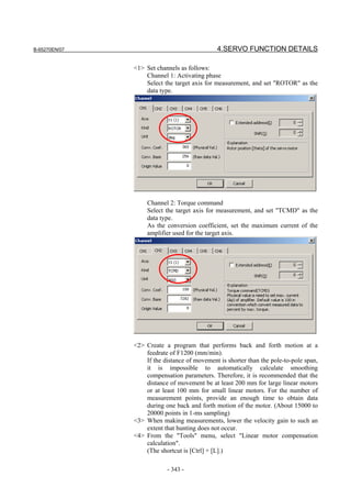
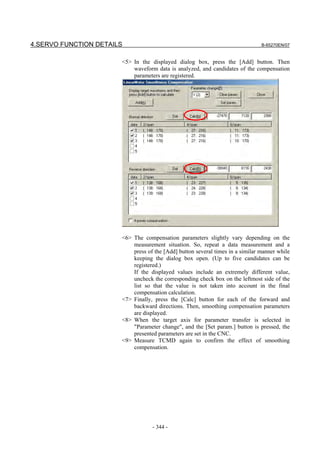
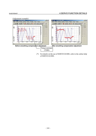
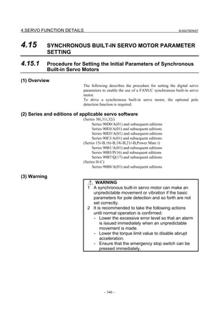
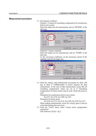
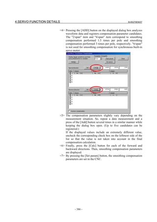
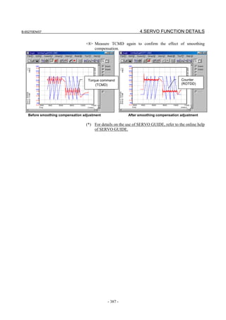
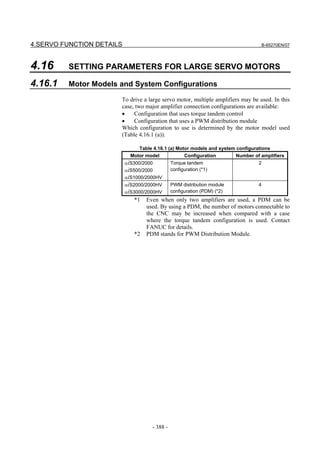
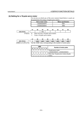
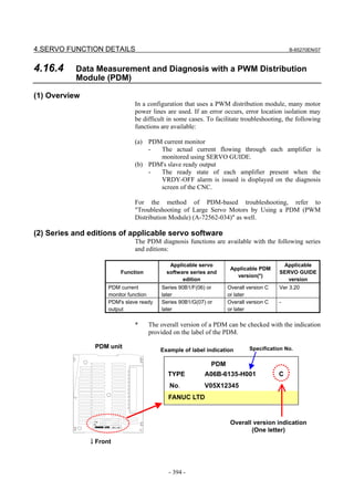
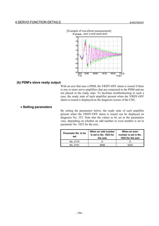
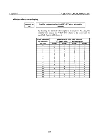
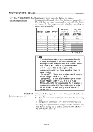
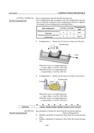
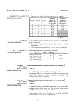
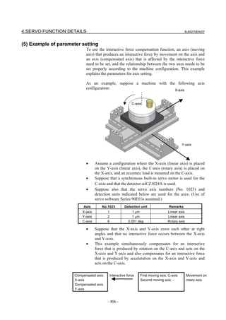
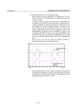
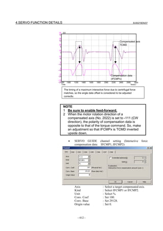
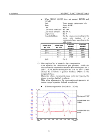
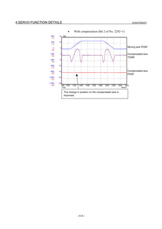
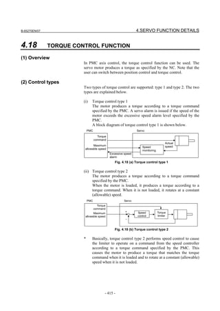
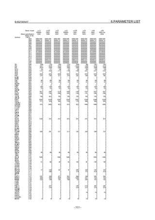
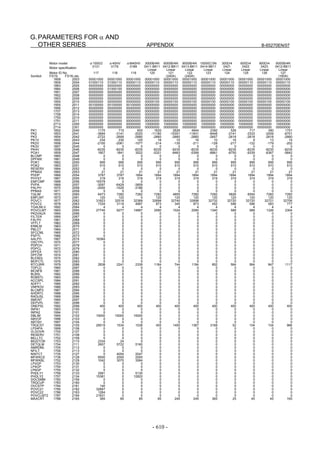
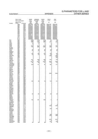
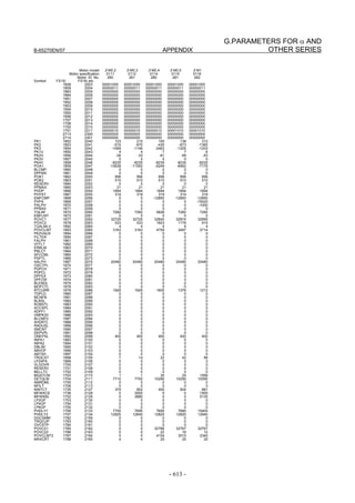
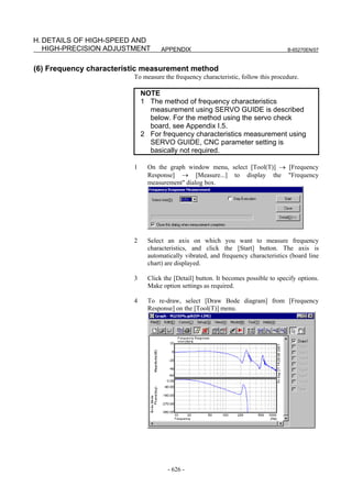
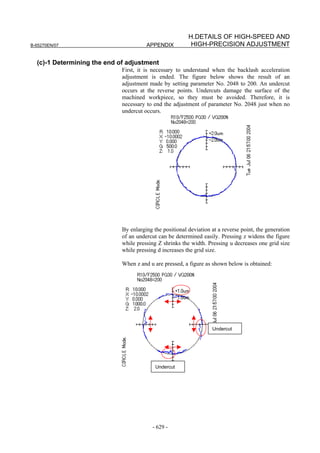
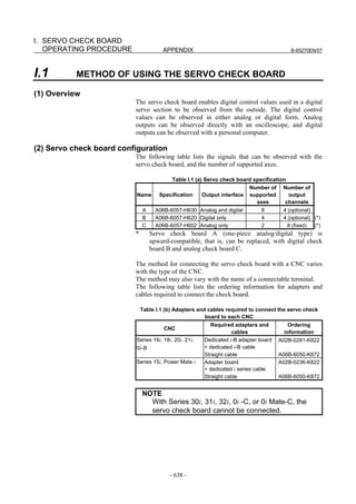
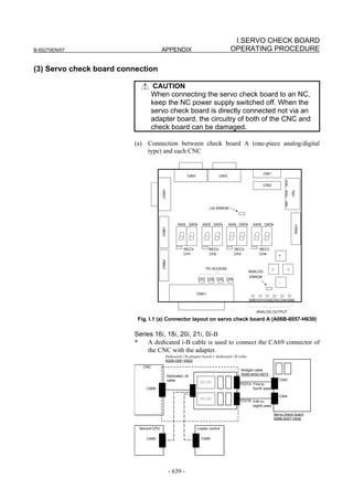
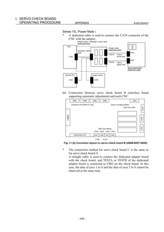
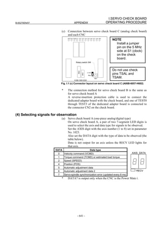
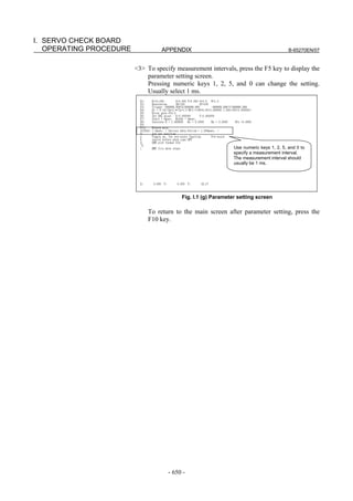
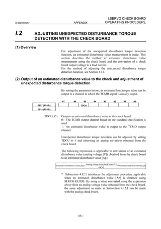
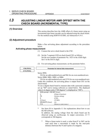
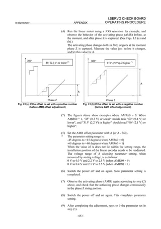
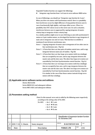
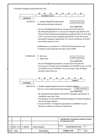
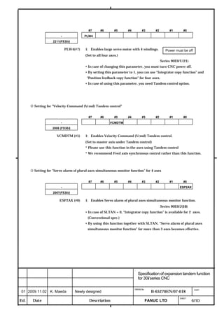
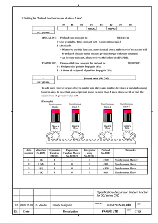
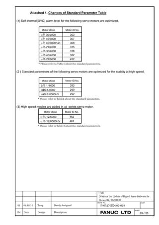
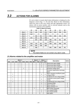
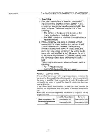
This document provides parameter manuals for FANUC AC servo motors, linear motors, and synchronous built-in servo motors. It describes how to initialize servo parameters, adjust parameters, and details various servo functions. The document contains safety information, tables of contents, sections on setting parameters, parameter adjustment, function details, parameter details, and appendices.


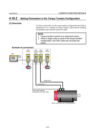
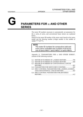
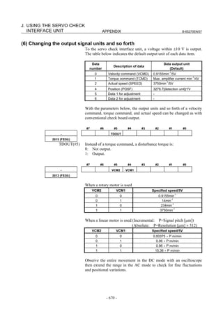
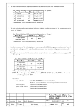
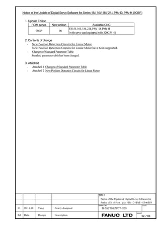
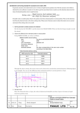
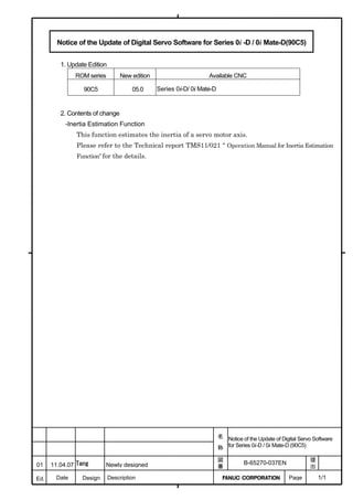
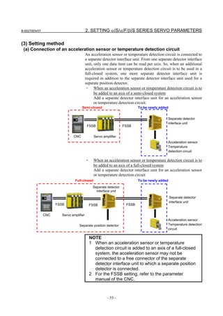
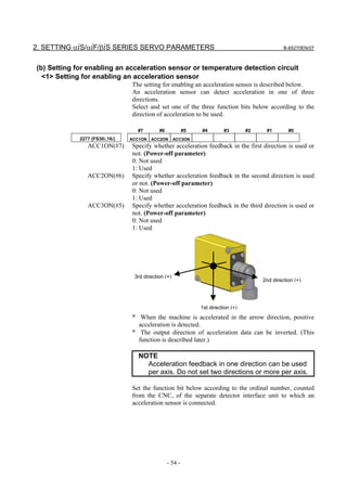
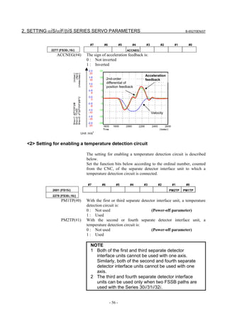
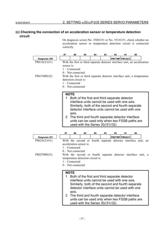
![B-65270EN/07 2. SETTING αiS/αiF/βiS SERIES SERVO PARAMETERS
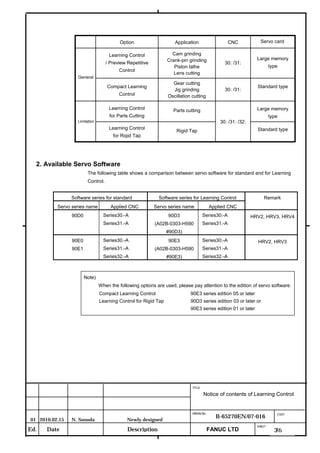
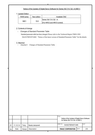
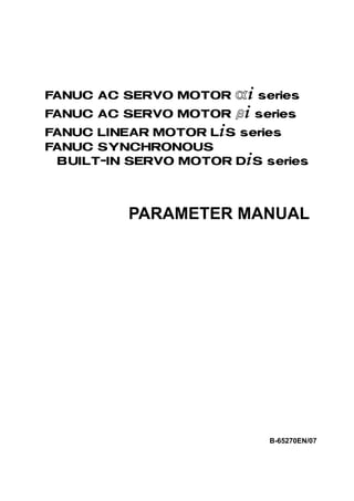
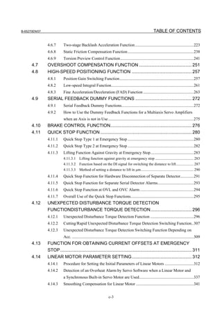
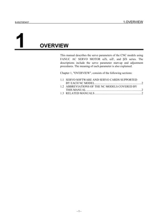
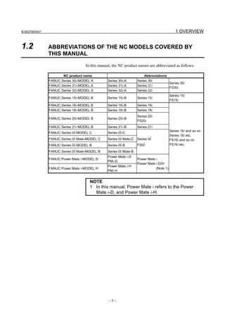
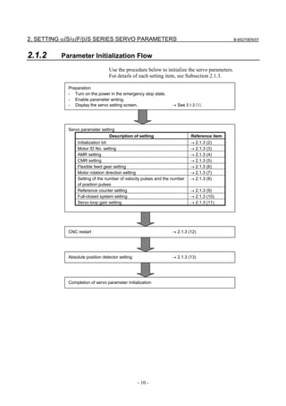
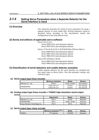
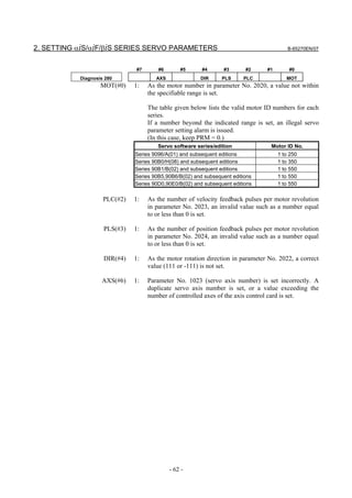
2.1.3 Servo Parameter Initialization Procedure
(1) Preparation
Switch on the NC in an emergency stop state.
Enable parameter writing (PWE = 1).
Initialize servo parameters on the servo setting screen.
For a Power Mate i with no CRT, specify a value for an item number
on the servo setting screen. See Fig. 2.1.3.
To display the servo setting screen, follow the procedure below, using
the key on the NC.
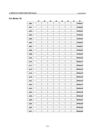
- Series 15i
Press the SYSTEM
function key several times, and the servo setting
screen will appear.
- Series 0i-C
Press the function key several times until the PARAMETER
SETTING SUPPORT screen appears.
Press soft key [(OPRT)], move the cursor to the SERVO SETTING
item, and press [SELECT] to display the PARAMETER SETTING
SUPPORT screen.
Fig. 2.1.3(a) PARAMETER SETTING SUPPORT screen
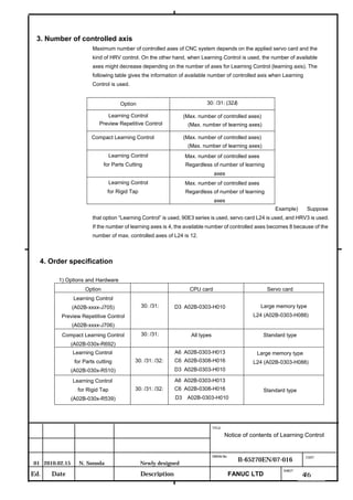
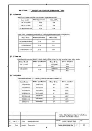
With 0i-C, two types of servo setting screens are available: the
standard screen and the conventional compatible screen. Initialization
can be performed by using either of the screens. This manual
describes the method of setting using the conventional compatible
screen.
For the standard screen, refer to "FANUC Series 0i-MODEL C/0i
Mate- MODEL C START-UP MANUAL (B-64114EN-1)".
- 11 -](https://image.slidesharecdn.com/b-65270en07-121129013640-phpapp01/85/B-65270-en-07-21-320.jpg)
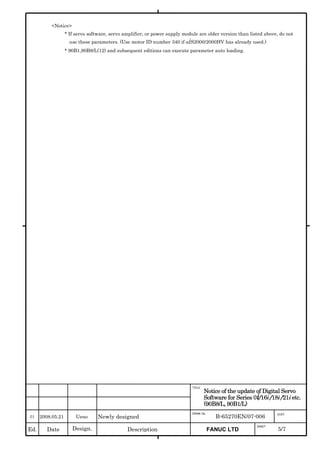
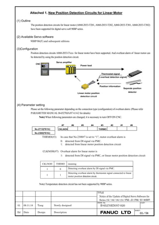
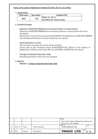
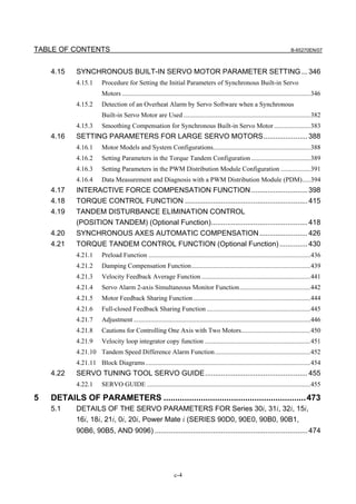
![2. SETTING αiS/αiF/βiS SERIES SERVO PARAMETERS B-65270EN/07
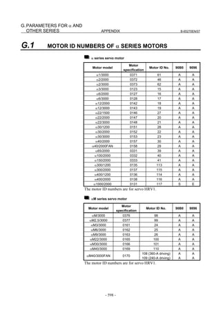
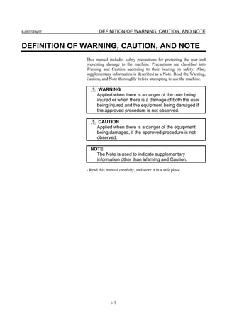
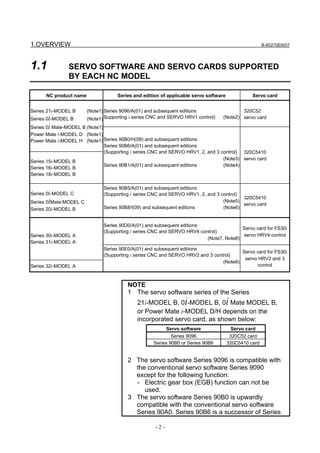
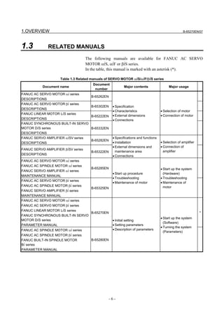
(Standard screen) (Conventional compatible screen)
Fig. 2.1.3(b) 0i-C Servo tuning screen
When the servo setting screen (standard screen) is displayed, the servo
setting screen (conventional compatible screen) can be displayed by
operating the soft keys as follows:
[(OPRT)] → [ ] → [CHANGE]
- Series30i,31i,32i,16i,18i,21i,20i,0i-B
→ [SYSTEM] → [ ] → [SV-PRM]
If no servo screen appears, set the following parameter as shown, and
switch the NC off and on again.
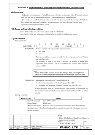
#7 #6 #5 #4 #3 #2 #1 #0
3111 SVS
SVS (#0) 1: Displays the servo screen.
When the following screen appears, move the cursor to the item you
want to specify, and enter the value directly.
Power Mate
Servo set 01000 N0000
X axis Z axis
INITIAL SET BITS 00001010 00001010 No.2000
Motor ID No. 16 16 No.2020
AMR 00000000 00000000 No.2001
CMR 2 2 No.1820
Feed gear N 1 1 No.2084
(N/M) M 100 100 No.2085
Direction Set 111 111 No.2022
Velocity Pulse No. 8192 8192 No.2023
Position Pulse No. 12500 12500 No.2024
Ref. counter 10000 10000 No.1821
Fig. 2.1.3(c) Servo setting screen Correspondence of Power Mate i
- 12 -](https://image.slidesharecdn.com/b-65270en07-121129013640-phpapp01/85/B-65270-en-07-22-320.jpg)
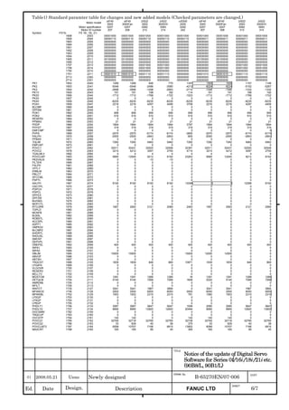
![B-65270EN/07 2. SETTING αiS/αiF/βiS SERIES SERVO PARAMETERS
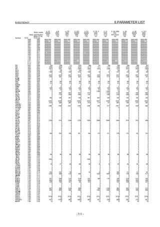
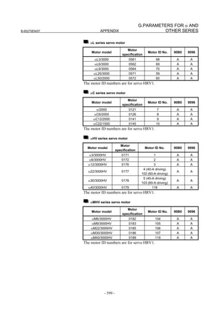
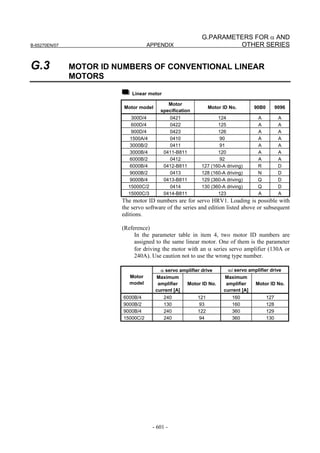
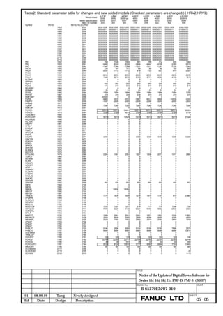
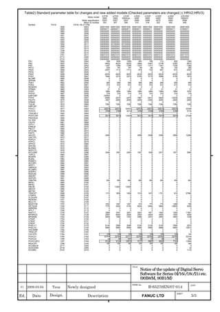
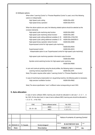
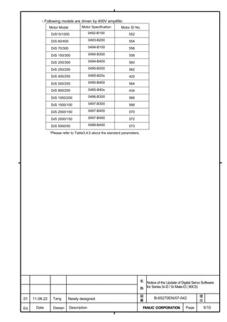
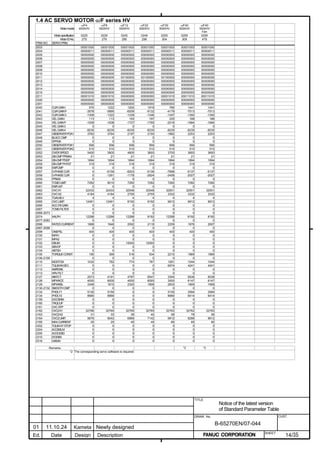
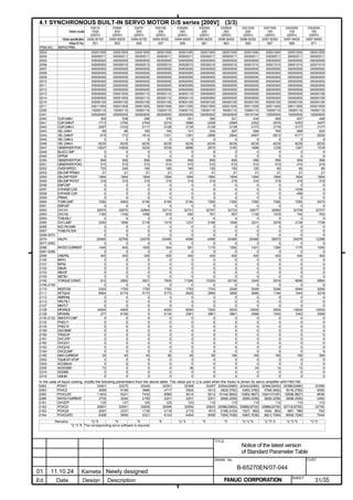
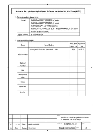
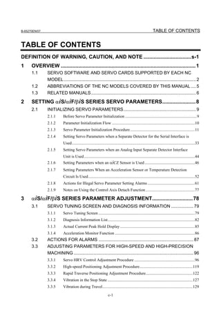
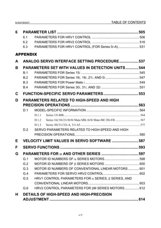
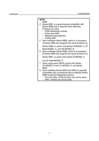
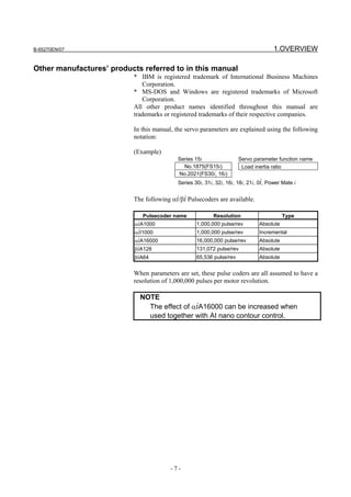
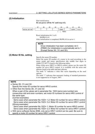
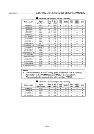
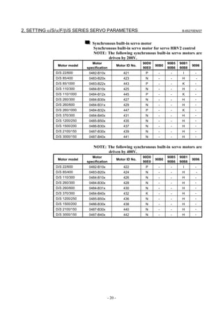
Linear motor parameters for servo HRV1 control
Motor 90D0 90B5
Motor model Motor ID No. 90B0 90B1 9096
specification 90E0 90B6
LiS 1500B1/4 0444-B210 90 A A A A A
LiS 3000B2/2 0445-B110 91 A A A A A
LiS 6000B2/2 0447-B110 92 A A A A A
LiS 9000B2/2 0449-B110 93 A A A A A
LiS 1500C2/2 0456-B110 94 A A A A A
LiS 3000B2/4 0445-B210 120 A A A A A
LiS 6000B2/4 0447-B210 121 A A A A A
LiS 9000B2/4 0449-B210 122 A A A A A
LiS 15000C2/3 0456-B210 123 A A A A A
LiS 300A1/4 0441-B200 124 A A A A A
LiS 600A1/4 0442-B200 125 A A A A A
LiS 900A1/4 0443-B200 126 A A A A A
127 A A A D
LiS 6000B2/4 0412-B811 R
(160-A driving)
128 A A A D
LiS 9000B2/2 0413 N
(160-A driving)
129 A A A D
LiS 9000B2/4 0413-B811 Q
(360-A driving)
130 A A A D
LiS 15000C2/2 0414 Q
(360-A driving)
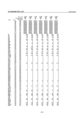
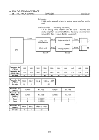
(Reference)
The parameter table presented in Chapter 6 has two motor ID Nos. for
the same linear motor. One of the two is for driving the α series servo
amplifiers (130A and 240A). Be careful not to use the wrong ID No.
α servo amplifier driving αi servo amplifier driving
Motor model Amplifier Amplifier
maximum Motor ID No. maximum Motor ID No.
current [A] current [A]
LiS 6000B2/4 240 121 160 127
LiS 9000B2/2 130 93 160 128
LiS 9000B2/4 240 122 360 129
LiS 15000C2/2 240 94 360 130
- 19 -](https://image.slidesharecdn.com/b-65270en07-121129013640-phpapp01/85/B-65270-en-07-29-320.jpg)
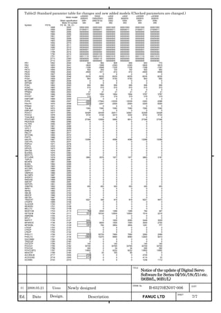
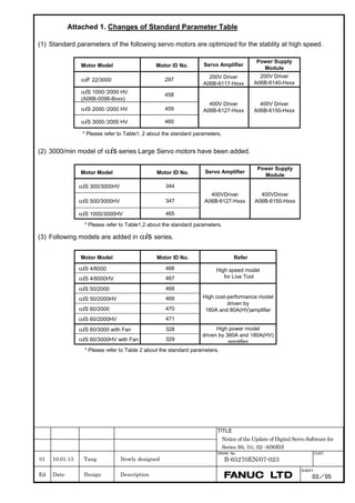
![2. SETTING αiS/αiF/βiS SERIES SERVO PARAMETERS B-65270EN/07
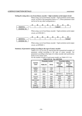
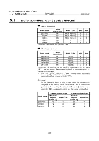
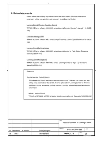
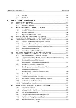
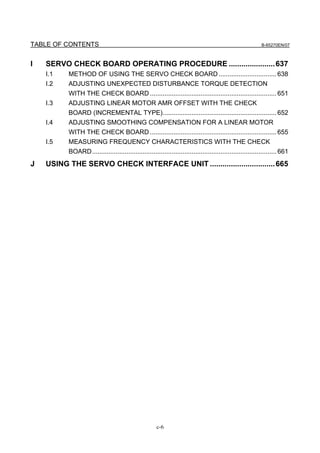
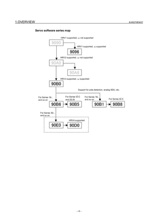
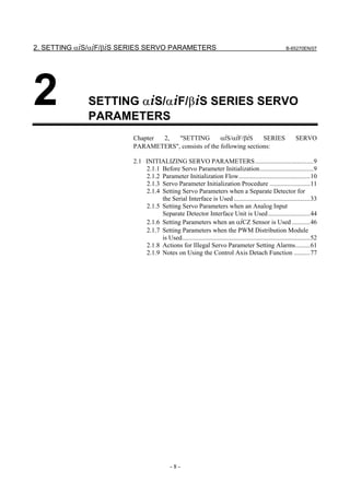
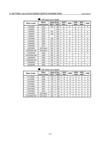
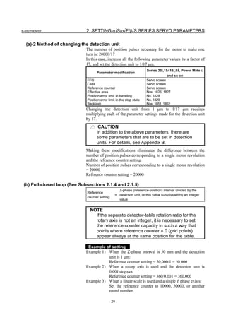
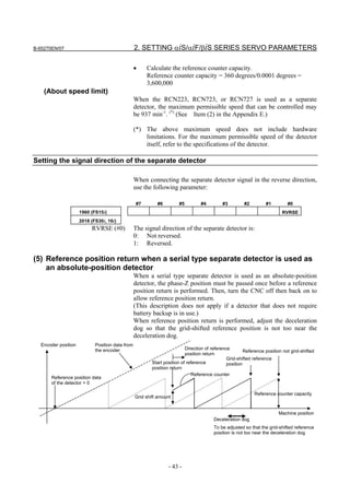
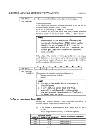
(a)-1 Method that sets a reference counter capacity with a fraction
(a)-2 Method that changes the detection unit
An example of each setting method is explained below.
(a)-1 Method of specifying the reference counter capacity with a fraction (except
Series 9096)
The number of position pulses necessary for the motor to make one
turn is: 20000/17
Set the following parameter as stated below.
1896 (FS15i) Reference counter capacity (numerator)
1821 (FS30i, 16i)
[Valid data range] 0 to 99999999
Set the numerator of a fraction for the reference counter capacity.
2622 (FS15i) Reference counter capacity (denominator)
2179 (FS30i, 16i)
[Valid data range] 0 to 100
A value up to around 100 is assumed to be set as the denominator of
the reference counter capacity. Note that if a larger value is set, the
grid width becomes too small, which makes it difficult to perform
reference position return by grid method.
The denominator parameter is not indicated in the servo setting screen,
so it must be set in the parameter screen.
In this example, set the numerator and denominator, respectively, to
20000 and 17.
NOTE
Even if a setting is made with a fraction, set the
number of position pulses per motor revolution/M for
a semi-closed loop rotary axis when the reduction
ratio is M/N.
Reference counter =
Number of position pulses per motor revolution/M, or
The same number divided by an integer
- 28 -](https://image.slidesharecdn.com/b-65270en07-121129013640-phpapp01/85/B-65270-en-07-38-320.jpg)
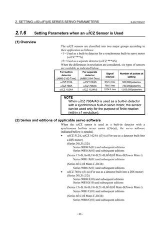
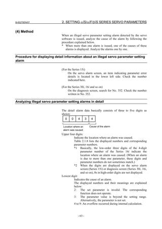
![2. SETTING αiS/αiF/βiS SERIES SERVO PARAMETERS B-65270EN/07
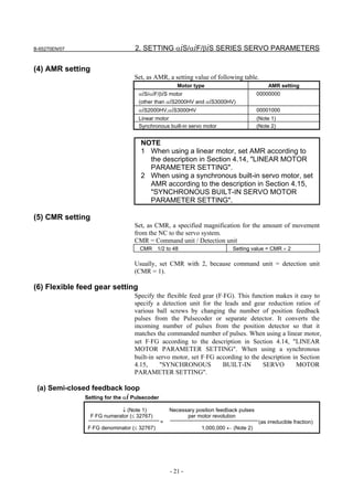
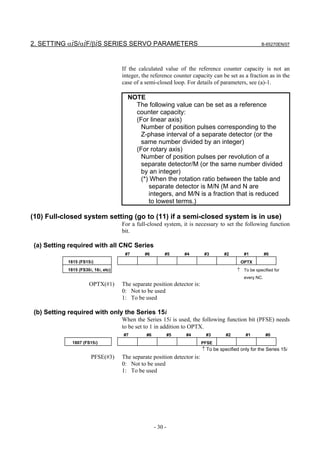
(d) RCN220, RCN223, RCN723, and RCN727 manufactured by HEIDENHAIN
Minimum resolution (Note 1) Model Backup
20
HEIDENHAIN 2 pulse/rev RCN220 Not required
223 pulse/rev RCN223, 723 Not required
227 pulse/rev RCN727 Not required
NOTE
1 The minimum resolution of a rotary encoder is the resolution of the
encoder itself. For the FANUC systems, however, please set
parameters with regarding the number of pulses/rev as follows:
One million pulses/rev for a minimum resolution of 220 pulses/rev
Eight million pulses/rev for a minimum resolution of 223 pulses/rev
Eight million pulses/rev for a minimum resolution of 227 pulses/rev
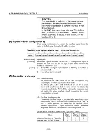
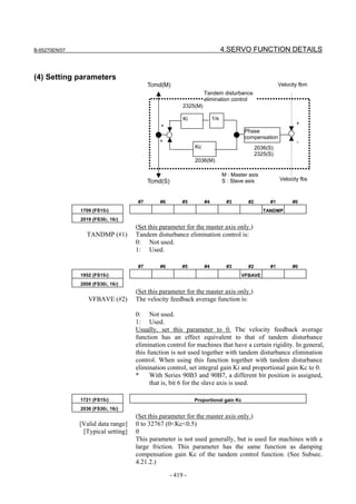
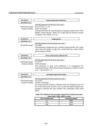
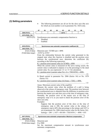
(4) Setting parameters
Set the following parameters according to the type of the detector
(described in the previous item).
(a) Parameter setting for a linear encoder of a serial output type
(Parameter setting method)
In addition to the conventional settings for a separate detector (bit 1 of
parameter No. 1815 (Series30i,15i,16i,18i,21i,20i,0i, and Power Mate
i), bit 3 of parameter No. 1807 (Series 15i), and if needed, FSSB),
note the following parameters:
[Flexible feed gear]
Parameter Nos. 1977 and 1978 (Series 15i) or Nos. 2084 and 2085
(Series 30i, 16i and so on)
Flexible feed gear (N/M) =
Minimum resolution of detector [µm] / controller detection unit [µm]
[Number of position pulses]
Parameter No. 1891 (Series 15i) or No. 2024 (Series 30i, 16i and so
on)
Number of position pulses =
Amount of movement per motor revolution [mm] /
detection unit of the sensor [mm]
* If the result of the above calculation does not fall in the setting
range (0 to 32767) for the number of position pulses, use
“position feedback pulse conversion coefficient” to specify the
number of position pulses according to the following procedure.
Number of position pulses to be set = A × B
Select B so that A is within 32767. Then, set the following:
A: Position pulses parameter (32767 or less)
No.1891 (Series15i), No.2024 (Series 30i, 16i and so on)
B: Position pulses conversion coefficient parameter
No.2628 (Series15i), No.2185 (Series 30i, 16i and so on)
- 34 -](https://image.slidesharecdn.com/b-65270en07-121129013640-phpapp01/85/B-65270-en-07-44-320.jpg)
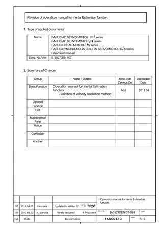
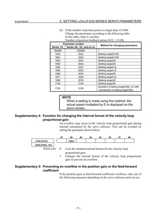
![B-65270EN/07 2. SETTING αiS/αiF/βiS SERIES SERVO PARAMETERS
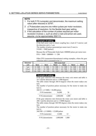
(Example of parameter setting)
[System configuration]
• The Series 16i is used.
• A linear scale with a minimum resolution of 0.1 µm is used.
• The least input increment of the controller is 1 µm.
• The amount of movement per motor revolution is 16 mm.
[Parameter setting]
• To enable a separate detector, set bit 1 of parameter No. 1815 to
1.
• Calculate the parameters for the flexible feed gear.
Because flexible feed gear (N/M) = 0.1 µm/1 µm = 1/10:
No. 2084 = 1 and No. 2085 = 10
• Calculate the number of position pulses.
Number of position pulses = 16 mm/0.0001mm = 160000
Because this result does not fall in the setting range (0 to 32767),
set A and B, respectively, with the "number of position pulses"
and "position pulses conversion coefficient" by assuming:
160,000 = 10,000 × 16 → A = 10,000 and B = 16
No.2024 = 10,000, No.2185 = 16
(b) Parameter setting for analog output type linear encoder +
FANUC high-resolution serial output circuit
(Parameter setting method)
In addition to the conventional separate detector settings (bit 1 of
parameter No. 1815 (Series15i,30i,16i,18i,21i,20i,0i, and Power Mate
i), bit 3 of parameter No. 1807 (Series 15i), and, if necessary, FSSB
setting), pay attention to the following parameter settings.
First check the type of the FANUC high-resolution output circuit to be
coupled to the linear encoder, and then determine the settings of the
following function bits.
[Function bit]
Interpolation
Circuit Specification
magnification
High-resolution serial output circuit A860-0333-T501 512
High-resolution serial output circuit H A860-0333-T701 2048
High-resolution serial output circuit C A860-0333-T801 2048
- 35 -](https://image.slidesharecdn.com/b-65270en07-121129013640-phpapp01/85/B-65270-en-07-45-320.jpg)
![2. SETTING αiS/αiF/βiS SERIES SERVO PARAMETERS B-65270EN/07
#7 #6 #5 #4 #3 #2 #1 #0
2687 (FS15i) HP2048
2274 (FS30i, 16i)
HP2048(#0) The 2048-magnification interpolation circuit (high-resolution serial
output circuit H or C) is:
0: Not to be used
1: To be used
NOTE
1 When high-resolution serial output circuit H is used,
set the setting pin SW3 inside the circuit to "Setting
B" usually.
2 This function bit can be used with the following
series and editions:
(Series 30i, 31i, 32i)
Series 90D0/A(01) and subsequent editions
Series 90E0/A(01) and subsequent editions
(Series 15i-B, 16i-B, 18i-B, 21i-B, 0i-B, 0i Mate-B,
Power Mate i)
Series 90B0/Q(17) and subsequent editions
Series 90B1/A(01) and subsequent editions
Series 90B6/A(01) and subsequent editions
(Series 0i-C, 0i Mate-C, 20i-B)
Series 90B5/A(01) and subsequent editions
Series 90B8/A(01) and subsequent editions
If this bit is specified, the minimum resolution
setting of the detector is assumed to be:
Encoder signal pitch/512 [µm]
If the minimum resolution (signal pitch/2048 [µm])
is necessary as the detection unit, specify:
Flexible feed gear = 4/1
3 When high-resolution serial output circuit H is used,
and the input frequency 750 kHz needs to be
supported, set the following:
- Set the setting pin SW3 to "Setting A".
- Set HP2048=1.
- Set the minimum resolution of the detector as:
Encoder signal pitch/128 [µm]
(Related report: TMS03/16E)
- 36 -](https://image.slidesharecdn.com/b-65270en07-121129013640-phpapp01/85/B-65270-en-07-46-320.jpg)
![B-65270EN/07 2. SETTING αiS/αiF/βiS SERIES SERVO PARAMETERS
[Minimum resolution of the detector]
In the following calculation of a flexible feed gear and the number of
position pulses, the minimum detector resolution to be used is:
(Linear encoder signal pitch/512 [µm])
(Specifying the above function bit appropriately makes it unnecessary
to take the difference in the interpolation magnification among the
high-resolution serial output circuits into account. So always use 512
for calculations.)
[Flexible feed gear]
Parameters Nos. 1977 and 1978 (Series 15i) or Nos. 2084 and 2085
(Series 30i, 16i, and so on)
Flexible feed gear (N/M)
= minimum resolution of the detector [µm] /
detection unit of controller [µm]
[Number of position pulses]
Parameter No. 1891 (Series 15i) or No. 2024 (Series 30i, 16i, and so
on)
Number of position pulses
= Amount of movement per motor revolution [mm] /
minimum resolution of the detector [mm]
* If the result of the above calculation does not fall in the setting
range (0 to 32767) for the number of position pulses, use
“position feedback pulse conversion coefficient” to specify the
number of position pulses according to the following procedure.
Number of position pulses to be set = A × B
Select B so that A is within 32767. Then, set the following:
A: Position pulses parameter (32767 or less)
No.1891 (Series15i), No.2024 (Series 30i, 16i, and so on)
B: Position pulses conversion coefficient parameter
No.2628 (Series15i), No.2185 (Series 30i, 16i, and so on)
(Example of parameter setting)
[System configuration]
• The Series 16i is used.
• A linear encoder with a signal pitch of 20 µm is used.
• The linear encoder is coupled with high-resolution serial output
circuit H.
• The least input increment of the controller is 1 µm.
• The amount of movement per motor revolution is 16 mm.
[Parameter setting]
• To enable a separate detector, set bit 1 of parameter No. 1815 to
1.
• To use high-resolution serial output circuit H, set bit 0 of
parameter No. 2274 to 1.
Minimum resolution of the detector = 20 µm/512
= 0.0390625 µm
- 37 -](https://image.slidesharecdn.com/b-65270en07-121129013640-phpapp01/85/B-65270-en-07-47-320.jpg)
![2. SETTING αiS/αiF/βiS SERIES SERVO PARAMETERS B-65270EN/07
• Calculate the parameters for the flexible feed gear.
Because flexible feed gear (N/M)=(20/512µm)/1µm=5/128
No.2084=5, No.2085=128
• Calculate the number of position pulses.
Number of position pulses = 16 mm/(20/512µm) = 409,600
Because this result does not fall in the setting range (0 to 32767),
set A and B, respectively, with the "number of position pulses"
and "position pulses conversion coefficient" by assuming:
409,600 = 25,600 × 16 → A = 25,600, B = 16
No.2024 = 25,600, No.2185 = 16
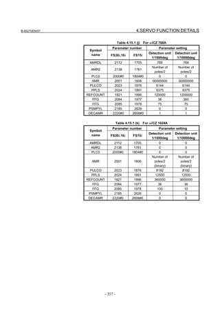
(c) Parameter setting for the serial output type rotary encoder
* For explanations about the rotary encoders RCN220, RCN223,
RCN723, and RCN727 made by HEIDENHAIN, see "Parameter
setting for the rotary encoders RCN220, RCN223, RCN723, and
RCN727 made by HEIDENHAIN."
(Parameter setting method)
In addition to the conventional settings for a separate detector (bit 1 of
parameter No. 1815 (Series15i, 30i, 16i, 18i, 21i, 20i, 0i, and Power
Mate i), bit 3 of parameter No. 1807 (Series 15i), and if needed,
FSSB), note the following parameters:
[Flexible feed gear]
Parameters Nos. 1977 and 1978 (Series 15i) or Nos. 2084 and 2085
(Series 30i, 16i and so on)
Flexible feed gear (N/M) =
(Amount of table movement [deg] per detector revolution) /
(detection unit [deg]) / 1,000,000
[Number of position pulses]
Parameter No. 1891 (Series 15i) or No. 2024 (Series 30i, 16i and so
on)
Number of position pulses = 12500×(motor-to-table reduction ratio)
* If the result of the above calculation does not fall in the setting
range (0 to 32767) for the number of position pulses, use
“position feedback pulse conversion coefficient” to specify the
number of position pulses according to the following procedure.
Number of position pulses to be set = A × B
Select B so that A is within 32767. Then, set the following:
A: Position pulses parameter (32767 or less)
No.1891 (Series15i), No.2024 (Series 30i, 16i and so on)
B: Position pulses conversion coefficient parameter
No.2628 (Series15i), No.2185 (Series 30i, 16i and so on)
- 38 -](https://image.slidesharecdn.com/b-65270en07-121129013640-phpapp01/85/B-65270-en-07-48-320.jpg)
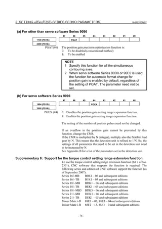
![B-65270EN/07 2. SETTING αiS/αiF/βiS SERIES SERVO PARAMETERS
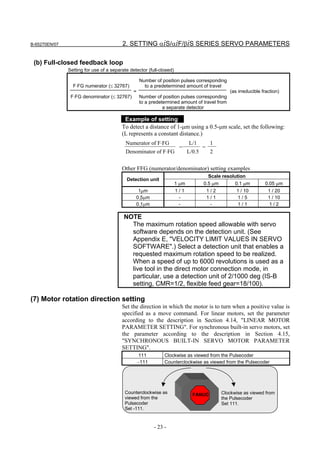
(Example of parameter setting)
[System configuration]
• The Series 16i is used.
• The least input increment of the controller is 1/1000 degrees.
• The amount of movement per motor revolution is 180 degrees
(reduction ratio: 1/2)
• Table-to-separate-encoder reduction ratio = 1/1
[Parameter setting]
• To enable a separate detector, set bit 1 of parameter No. 1815 to
1.
• Calculate the parameters for the flexible feed gear.
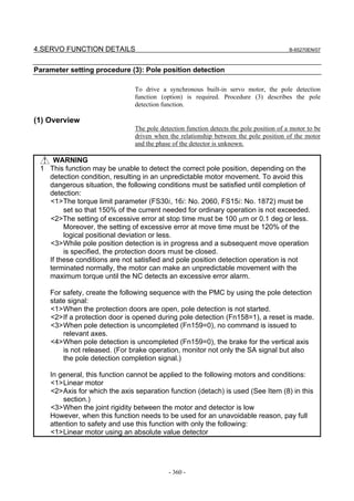
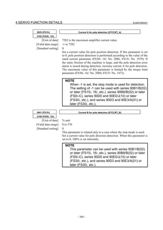
Because flexible feed gear (N/M)
=360 degrees /0.001 degrees /1,000,000 =36/100
No.2084=36, No.2085=100
• Calculate the number of position pulses.
Because number of position pulses = 12500 × (1/2)=6250
No.2024=6250
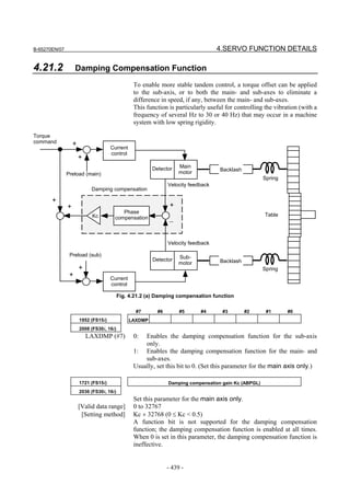
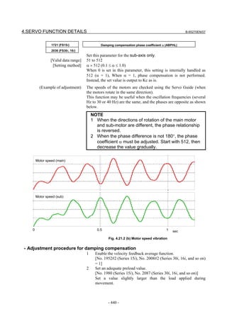
- 39 -](https://image.slidesharecdn.com/b-65270en07-121129013640-phpapp01/85/B-65270-en-07-49-320.jpg)
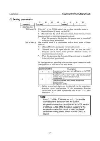
![2. SETTING αiS/αiF/βiS SERIES SERVO PARAMETERS B-65270EN/07
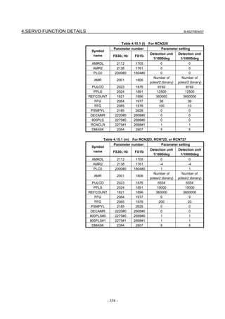
(d) Parameter setting for the rotary encoders RCN220, RCN223, RCN723, and
RCN727 made by HEIDENHAIN
(Series and editions of applicable servo software)
To use the high-resolution rotary encoders RCN220, RCN223,
RCN723, and RCN727 manufactured by HEIDENHAIN as separate
detectors, the following servo software is required:
[RCN220,223,723]
(Series 30i,31i,32i)
Series 90D0/A(01) and subsequent editions
Series 90E0/A(01) and subsequent editions
(Series 15i-B,16i-B,18i-B,21i-B,0i-B,0i Mate-B,Power Mate i)
Series 90B0/T(19) and subsequent editions
Series 90B1/A(01) and subsequent editions
Series 90B6/A(01) and subsequent editions
(Series 0i-C,0i Mate-C,20i-B)
Series 90B5/A(01) and subsequent editions
Series 90B8/A(01) and subsequent editions
[RCN727]
(Series 30i,31i,32i)
Series 90D0/J(10) and subsequent editions
Series 90E0/J(10) and subsequent editions
(Series 15i-B,16i-B,18i-B,21i-B,0i-B,0i Mate-B,Power Mate i)
Series 90B1/B(02) and subsequent editions
(Series 0i-C,0i Mate-C,20i-B)
Series 90B8/B(02) and subsequent editions
(Parameter setting method)
To specify parameters for the high-resolution rotary encoders
RCN220, RCN223, RCN723, and RCN727 (supporting FANUC serial
interface) made by HEIDENHAIN, use the following procedure.
In addition to the conventional separate detector settings (bit 1 of
parameter No. 1815 (Series 30i, 15i, 16i, 18i, 21i, 0i, and Power Mate
i), bit 3 of parameter No. 1807 (Series 15i), and, if necessary, FSSB
setting), pay attention to the following parameter settings.
[Function bit]
To use the RCN220, RCN223, RCN723, or RCN727, set the
following function bit to 1.
#7 #6 #5 #4 #3 #2 #1 #0
2688 (FS15i) RCNCLR 800PLS
2275 (FS30i, 16i)
800PLS (#0) A rotary encoder with eight million pulses per revolution is:
0: Not to be used. (To use the RCN220, leave this bit set to 0.)
1: To be used. (To use the RCN223, RCN723, or RCN727, set the
bit to 1.)
- 40 -](https://image.slidesharecdn.com/b-65270en07-121129013640-phpapp01/85/B-65270-en-07-50-320.jpg)
![B-65270EN/07 2. SETTING αiS/αiF/βiS SERIES SERVO PARAMETERS
RCNCLR (#1) The number of revolution is:
0: Not to be cleared.
1: To be cleared. (To use the RCN220, RCN223, RCN723, or
RCN727, set the bit to 1.)
This function bit is to be set in combination with the number of data
mask digits, described below.
2807 (FS15i) Number of data mask digits
2394 (FS30i, 16i)
[Settings] 8. (To use the RCN223, RCN723, or RCN727)
5. (To use the RCN220)
The value to be set in this parameter depends on the detector. At
present, only the above detectors require clearing the speed data.
This parameter is to be set in combination with RCNCLR, described
above.
NOTE
The speed data of the RCN220, RCN223,
RCN723, or RCN727 is maintained while the power
to the separate detector interface unit is on. The
data, however, is cleared when the unit is turned
off. Since the speed data becomes undetermined
depending on where the power is turned off, it is
necessary to make a setting to clear the speed
data. In addition, for this reason, the RCN220,
RCN223, RCN723, and RCN727 cannot be used
with a linear axis.
When using the RCN220, set the parameters for the flexible feed gear
and the number of position pulses according to the setting method
described in the previous item, "Parameter setting for the serial output
type rotary encoder".
The following explains how to calculate the parameter values when
the RCN223, RCN723, or RCN727 is used.
[Flexible feed gear]
Parameters Nos. 1977 and 1978 (Series 15i) or Nos. 2084 and 2085
(Series 30i, 16i, and so on)
Flexible feed gear (N/M) =
(Amount of table movement [deg] per detector revolution) /
(detection unit [deg]) / 8,000,000
For the RCN223, RCN723, and RCN727, the number of pulses per
detector turn is assumed to be eight million for calculation.
For the RCN727, when the detection unit is set to 1/8,000,000
revolution or less, the flexible feed gear may be set to up to 8/1. (If the
flexible feed gear is set to 8/1, the detection unit is 64,000,000 pulses
per revolution.)
- 41 -](https://image.slidesharecdn.com/b-65270en07-121129013640-phpapp01/85/B-65270-en-07-51-320.jpg)
![2. SETTING αiS/αiF/βiS SERIES SERVO PARAMETERS B-65270EN/07
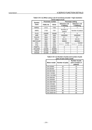
[Number of position pulses]
Parameter No. 1891 (Series 15i) or No. 2024 (Series 30i, 16i, and so
on)
Number of position pulses = 100,000×(motor-to-table reduction ratio)
* If the result of the above calculation does not fall in the setting
range (0 to 32767) for the number of position pulses, use
“position feedback pulse conversion coefficient” to specify the
number of position pulses according to the following procedure.
Number of position pulses to be set = A × B
Select B so that A is within 32767. Then, set the following:
A: Position pulses parameter (32767 or less)
No.1891 (Series15i), No.2024 (Series 30i, 16i, and so on)
B: Position pulses conversion coefficient parameter
No.2628 (Series15i), No.2185 (Series 30i, 16i, and so on)
[Reference counter capacity]
Parameter No. 1896 (Series 15i) or No. 1821 (Series 30i, 16i, and so
on)
Specify the number of feedback pulses per table turn (detection unit).
* If bit 0 of parameter No. 2688 (Series 15i) or parameter No. 2275
(Series 30i, 16i, and so on) is 0, specify the number of pulses per
table turn divided by 8 as the reference counter capacity. In this
case, eight grid points occur per table turn.
(Example of parameter setting)
[System configuration]
• The Series 16i is used.
• The rotary encoder RCN223 made by HEIDENHAIN is used.
• The least input increment of the controller is 1/10,000 degrees.
• The amount of movement per motor revolution is 180 degrees
(reduction ratio: 1/2)
• Table-to-separate-encoder reduction ratio = 1/1
[Parameter setting]
• To enable a separate detector, set bit 1 of parameter No. 1815 to
1.
• To use the detector RCN223, set bit 0 of parameter No. 2275 to 1,
bit 1 of this parameter to 1, and parameter No. 2394 to 8.
• Calculate the parameters for the flexible feed gear.
Because flexible feed gear (N/M) =
(360 degrees /0.0001 degrees)/8,000,000=9/20
No.2084=9, No.2085=20
• Calculate the number of position pulses.
Number of position pulses = 100,000 × (1/2) = 50,000
Because this result does not fall in the setting range (0 to 32767),
set A and B, respectively, with the "number of position pulses"
and "position pulses conversion coefficient" by assuming:
50,000 = 12,500 × 4 → A = 12,500, B = 4
No.2024 = 12,500, No.2185 = 4
- 42 -](https://image.slidesharecdn.com/b-65270en07-121129013640-phpapp01/85/B-65270-en-07-52-320.jpg)
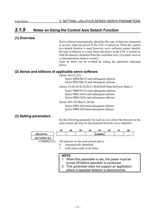
![2. SETTING αiS/αiF/βiS SERIES SERVO PARAMETERS B-65270EN/07
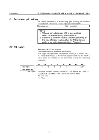
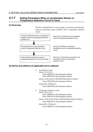
2.1.5 Setting Servo Parameters when an Analog Input Separate
Detector Interface Unit is Used
(1) Overview
An analog input separate detector interface unit (analog SDU) can be
connected directly to an encoder having an analog output signal of 1
Vp-p. This subsection explains parameter settings to be made when
this unit is connected to a separate detector. After performing the
initialization procedure (full-closed loop) described in Subsection
2.1.3, change the setting described below according to the signal pitch
of the detector.
Configuration where analog SDU is used
Separate detector
X 000.000
Y 000.000
Z 000.000
FSSB 1Vp-p
Analog SDU
(2) Series and editions of applicable servo software
(Series 30i,31i,32i)
Series 90D0/J(10) and subsequent editions
Series 90E0/J(10) and subsequent editions
(Series 15i-B,16i-B,18i-B,21i-B,0i-B,0i Mate-B,Power Mate i)
Series 90B1/C(03) and subsequent editions
(Series 0i-C,0i Mate-C)
Series 90B8/C(03) and subsequent editions
(3) Setting parameters
After performing the initialization (full-closed loop) described in
Subsection 2.1.3, change the following setting according to the signal
pitch of the detector:
[Setting the flexible feed gear]
1977 (FS15i) Numerator of flexible feed gear
2084 (FS30i,16i)
1978 (FS15i) Denominator of flexible feed gear
2085 (FS30i,16i)
Set the flexible feed gear according to the following equation.
(Equation for parameter calculation)
Detector signal pitch [µm]/512
Flexible feed gear (N/M) =
Detection unit of controller [µm]
- 44 -](https://image.slidesharecdn.com/b-65270en07-121129013640-phpapp01/85/B-65270-en-07-54-320.jpg)
![B-65270EN/07 2. SETTING αiS/αiF/βiS SERIES SERVO PARAMETERS
[Setting the number of position pulses]
1891 (FS15i) Number of position pulses (PPLS)
2024 (FS30i,16i)
Set the number of position pulses according to the following equation:
(Equation for parameter calculation)
Amount of movement per motor revolution [mm]
Number of position pulses =
Detector signal pitch [mm]/512
If the calculation result is greater than 32767, use the following
position pulse conversion coefficient (PSMPYL) to obtain the
parameter setting (PPLS).
2628 (FS15i) Position pulse conversion coefficient (PSMPYL)
2185 (FS30i,16ii)
This parameter is used when the calculation result of the number of
position pulses is greater than 32767.
(Equation for parameter calculation)
Set this parameter so that the following equation is satisfied:
Number of position pulses = PPLS × PSMPYL
(→ See Supplementary 3 in Subsection 2.1.8.)
(Example of parameter setting)
[System configuration]
• The Series 30i is used.
• A linear scale with a signal pitch of 20 µm is used.
• The least input increment of the controller is 1 µm.
• The amount of movement per motor revolution is 16 mm.
[Parameter setting]
• To enable a separate detector, set bit 1 of parameter No. 1815 to
1.
• Calculate the parameters for the flexible feed gear.
Because flexible feed gear (N/M)=(20/512µm)/1µm=5/128
No.2084=5, No.2085=128
• Calculate the number of position pulses.
Number of position pulses = 16 mm/(0.02 mm/512)= 409,600
Because this result does not fall in the setting range (0 to 32767),
set A and B, respectively, with the "number of position pulses"
and "position pulses conversion coefficient" by assuming:
409,600 = 25,600 × 16 → A = 25,600, B = 16
No.2024 = 25,600, No.2185 = 16
- 45 -](https://image.slidesharecdn.com/b-65270en07-121129013640-phpapp01/85/B-65270-en-07-55-320.jpg)
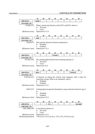
![B-65270EN/07 2. SETTING αiS/αiF/βiS SERIES SERVO PARAMETERS
• αiCZ 512AS, αiCZ 768AS, αiCZ 1024AS ((3)-(b) For use as a
separate detector)
(Series 30i,31i,32i)
Series 90D0/A(01) and subsequent editions
Series 90E0/A(01) and subsequent editions
(Series 15i-B,16i-B,18i-B,21i-B,0i-B,0i Mate-B,Power Mate i)
Series 90B0/A(01) and subsequent editions
Series 90B1/A(01) and subsequent editions
Series 90B6/A(01) and subsequent editions
(Series 0i-C,0i Mate-C,20i-B)
Series 90B5/A(01) and subsequent editions
Series 90B8/A(01) and subsequent editions
(3) Setting parameters
(a) Used as the detector for a synchronous built-in servo motor)
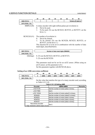
[Setting AMR]
#7 #6 #5 #4 #3 #2 #1 #0
1806 (FS15i) 0 AMR6 AMR5 AMR4 AMR3 AMR2 AMR1 AMR0
2001 (FS30i,16i)
Set the value listed below according to the detector.
Detector AMR
Set the number of poles of the synchronous built-in servo
αiCZ 512A
motor in binary.
αiCZ 768A Set 0.
Set a value obtained by dividing the number of poles of the
αiCZ 1024A
synchronous built-in servo motor by 2 in binary.
Setting example:
When an 88-pole synchronous built-in servo motor and the αiCZ
1024A are used:
Number of poles/2 = 88/2 = 44
→ The binary representation of the above value is 00101100.
This value is set in AMR.
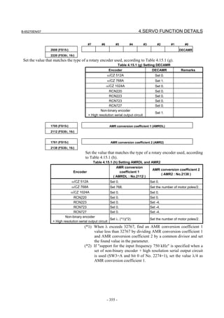
#7 #6 #5 #4 #3 #2 #1 #0
2608 (FS15i) DECAMR
2220 (FS30i,16i)
Set one of the following values according to the detector.
Detector DECAMR
αiCZ 512A Set 0.
αiCZ 768A Set 1.
αiCZ 1024A Set 0.
- 47 -](https://image.slidesharecdn.com/b-65270en07-121129013640-phpapp01/85/B-65270-en-07-57-320.jpg)
![2. SETTING αiS/αiF/βiS SERIES SERVO PARAMETERS B-65270EN/07
1705 (FS15i) AMR conversion coefficient 1
2112 (FS30i,16i)
1761 (FS15i) AMR conversion coefficient 2
2138 (FS30i,16i)
Set one of the following values according to the detector.
AMR conversion
Detector AMR conversion coefficient 2
coefficient 1
αiCZ 512A Set 0. Set 0.
αiCZ 768A Set 768. Set half the number of poles.
αiCZ 1024A Set 0. Set 0.
[Setting flexible feed gear]
1977 (FS15i) Flexible feed gear (numerator)
2084 (FS30i,16i)
1978 (FS15i) Flexible feed gear (denominator)
2085 (FS30i,16i)
Set the flexible feed gear according to the equation below.
The number of pulses per detector rotation is as follows:
Detector Flexible feed gear
Amount of movement per motor revolution [deg]/
αiCZ 512A detection unit [deg]
500,000
Amount of movement per motor revolution [deg]/
αiCZ 768A detection unit [deg]
750,000
Amount of movement per motor revolution [deg]/
αiCZ 1024A detection unit [deg]
1,000,000
(Equation for parameter calculation)
Amount of movement per motor revolution [deg]/
Flexible feed gear (N/M) = detection unit [deg]
Number of pulses per detector rotation
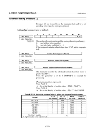
[Setting number of velocity pulses]
1876 (FS15i) Number of velocity pulses (PULCO)
2023 (FS30i,16i)
Set a value listed in the following table according to the detector used.
Detector Number of velocity pulses
αiCZ 512A 4096
αiCZ 768A 6144
αiCZ 1024A 8192
- 48 -](https://image.slidesharecdn.com/b-65270en07-121129013640-phpapp01/85/B-65270-en-07-58-320.jpg)
![B-65270EN/07 2. SETTING αiS/αiF/βiS SERIES SERVO PARAMETERS
[Setting number of position pulses]
1891 (FS15i) Number of position pulses (PPLS)
2024 (FS30i,16i)
Set a value listed in the following table according to the detector used.
Detector Number of position pulses
αiCZ 512A 6250
αiCZ 768A 9375
αiCZ 1024A 12500
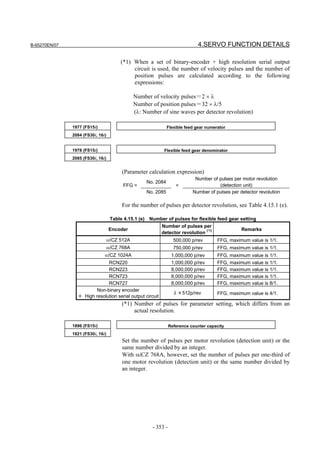
[Setting reference counter capacity]
1896 (FS15i) Reference counter capacity
1821 (FS30i,16i)
Set one of the following values according to the detector.
Detector Reference counter capacity
Set the number of pulses per motor revolution (detection
αiCZ 512A unit) or a value obtained by dividing that number by an
integer.
Set the number of pulses per 120-degree motor revolution
αiCZ 768A (one-third revolution) (detection unit) or a value obtained
by dividing that number by an integer.
Set the number of pulses per motor revolution (detection
αiCZ 1024A unit) or a value obtained by dividing that number by an
integer.
(Example of parameter setting)
[System configuration]
• The Series 30i is used.
• An 88-pole/rev, synchronous built-in servo motor is used.
• The detector used is the αiCZ512A.
• The least input increment of the controller is 1/1000 deg.
• Gear ratio 1:1
[Parameter setting]
AMR=01011000 (88 in decimal representation)
Flexible feed gear (N/M) = 360,000/500,000 = 18/25, so parameter No.
2084 = 18, and parameter No. 2085 = 25
Number of velocity pulses = 4096
Number of position pulses = 6250
Reference counter capacity = 360,000
- 49 -](https://image.slidesharecdn.com/b-65270en07-121129013640-phpapp01/85/B-65270-en-07-59-320.jpg)
![2. SETTING αiS/αiF/βiS SERIES SERVO PARAMETERS B-65270EN/07
(b) Used as a separate detector
After performing the initialization procedure (full-closed loop)
described in Subsection 2.1.3, change the settings described below
according to the signal pitch of the detector.
[Setting flexible feed gear]
1977 (FS15i) Flexible feed gear (numerator) (N)
2084 (FS30i,16i)
1978 (FS15i) Flexible feed gear (denominator) (M)
2085 (FS30i,16i)
Set a value listed in the following table according to the detector used.
Detector Flexible feed gear
Amount of movement per motor revolution [deg]/
αiCZ 512AS detection unit [deg]
500,000
Amount of movement per motor revolution [deg]/
αiCZ 768AS detection unit [deg]
750,000
Amount of movement per motor revolution [deg]/
αiCZ 1024AS detection unit [deg]
1,000,000
[Setting number of velocity pulses]
1876 (FS15i) Number of velocity pulses (PULCO)
2023 (FS30i,16i)
Set the number of velocity pulses to 8192.
[Setting number of position pulses]
1891 (FS15i) Number of position pulses (PPLS)
2024 (FS30i,16i)
Set a value listed in the following table according to the detector used.
Detector Number of position pulses
αiCZ 512AS 6250 × (gear reduction ratio from the motor to table)
αiCZ 768AS 9375 × (gear reduction ratio from the motor to table)
αiCZ 1024AS 12500 × (gear reduction ratio from the motor to table)
If the calculation result is greater than 32767, use the following
position pulse conversion coefficient (PSMPYL) to obtain the
parameter value (PPLS).
2628 (FS15i) Conversion coefficient for the number of position feedback pulses (PSMPYL)
2185 (FS30i,16i)
This parameter is used when the calculated number of position pulses
is greater than 32767.
(Equation for parameter calculation)
Set this parameter so that the following equation is satisfied:
Number of position pulses = PPLS × PSMPYL
(→ See Supplementary 3 in Subsection 2.1.8.)
- 50 -](https://image.slidesharecdn.com/b-65270en07-121129013640-phpapp01/85/B-65270-en-07-60-320.jpg)
![B-65270EN/07 2. SETTING αiS/αiF/βiS SERIES SERVO PARAMETERS
[Setting reference counter capacity]
1896 (FS15i) Reference counter capacity
1821 (FS30i,16i)
Set one of the following values according to the detector.
Detector Reference counter capacity
Set the number of pulses per revolution of the detector
αiCZ 512AS installed separately (detection unit) or a value obtained by
dividing that number by an integer.
Set the number of pulses per 120-degree revolution
(one-third revolution) of the detector installed separately
αiCZ 768AS
(detection unit) or a value obtained by dividing that
number by an integer.
Set the number of pulses per revolution of the detector
αiCZ 1024AS installed separately (detection unit) or a value obtained by
dividing that number by an integer.
(Example of parameter setting)
[System configuration]
• The Series 30i is used.
• The detector used is the αiCZ1024AS
• The least input increment of the controller is 1/1000 deg.
• Gear ratio 1:1
[Parameter setting]
Flexible feed gear (N/M) = 360,000/1,000,000=9/25,
so parameter No. 2084 = 9, and parameter No. 2085 = 25
Number of position pulses = 12500
Reference counter capacity = 360,000
- 51 -](https://image.slidesharecdn.com/b-65270en07-121129013640-phpapp01/85/B-65270-en-07-61-320.jpg)
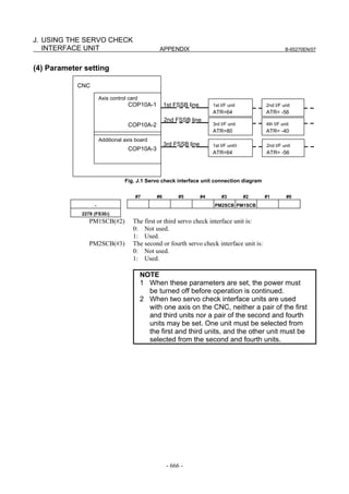
![B-65270EN/07 2. SETTING αiS/αiF/βiS SERIES SERVO PARAMETERS
#7 #6 #5 #4 #3 #2 #1 #0
2278 (FS30i,16i) PM2ACC
PM2ACC(#4) (Power-off parameter)
0: Acceleration sensor data is read from the first or third separate
detector interface unit counted from the CNC, or no acceleration
sensor is used.
1: Acceleration sensor data is read from the second or fourth
separate detector interface unit counted from the CNC.
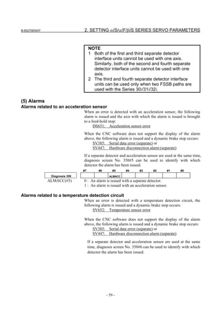
NOTE
1 Both of the first and third separate detector
interface units cannot be used with one axis.
Similarly, both of the second and fourth separate
detector interface units cannot be used with one
axis.
2 The third and fourth separate detector interface
units can be used only when two FSSB paths are
used with the Series 30i/31i/32i.
Set a detection unit in units of 1 nm.
2263 (FS30i,16i) Detection unit setting
[Setting unit] In units of 1 nm
Detection unit 10µm 1µm 0.1µm 0.01µm 0.001µm 0.05µm
Setting 10000 1000 100 10 1 50
To adjust the sign of acceleration feedback, observe position feedback
(POSF) and acceleration feedback (ACC) with SERVO GUIDE at
rapid traverse acceleration/deceleration time.
Set the sign bit ACCNEG for acceleration feedback below so that the
sign of the second-order differential of position feedback (POSF
indicated by Diff2(AT) operation) equals the sign of acceleration
feedback (ACC).
NOTE
The observation of ACC is supported by SERVO
GUIDE version 3.20 or later.
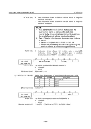
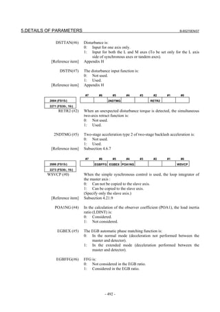
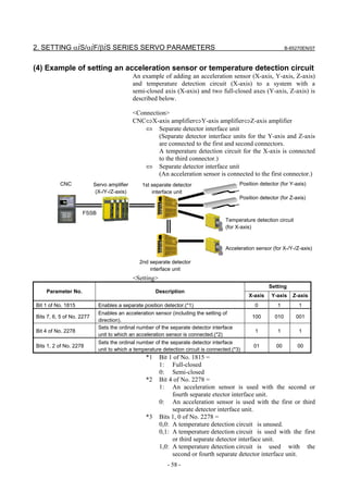
- 55 -](https://image.slidesharecdn.com/b-65270en07-121129013640-phpapp01/85/B-65270-en-07-65-320.jpg)
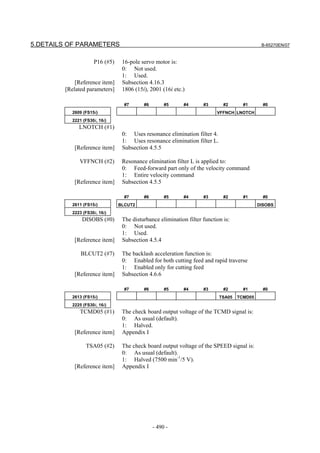
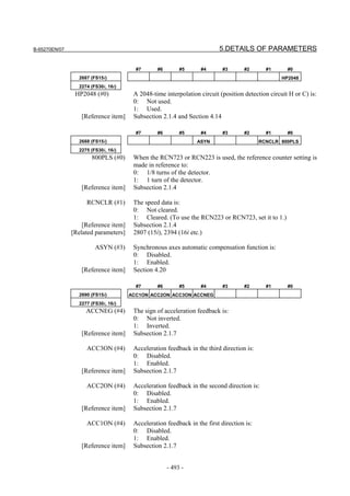
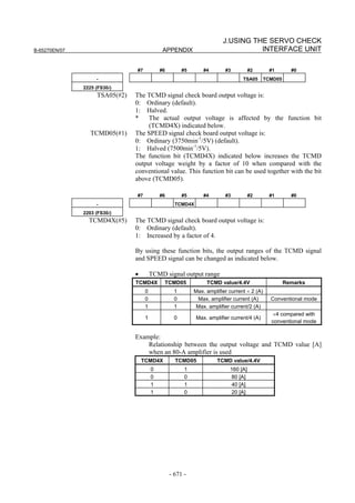
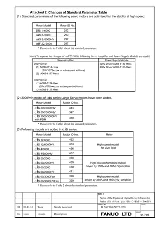
![B-65270EN/07 3. αiS/αiF/βiS SERIES PARAMETER ADJUSTMENT
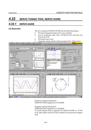
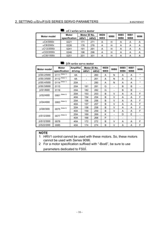
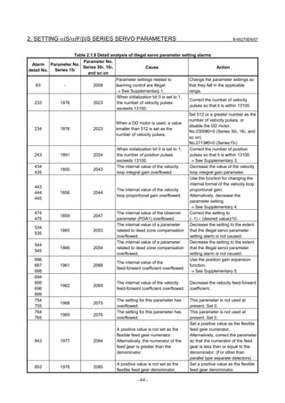
3.1 SERVO TUNING SCREEN AND DIAGNOSIS
INFORMATION
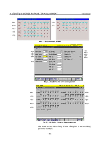
3.1.1 Servo Tuning Screen
Display the servo tuning screen, and check the position error, actual
current, and actual speed on the screen.
Using the keys on the CNC, enter values according to the procedure
explained below. (The Power Mate i DPL/MDI does not provide the
servo tuning function.)
- Series 15i
Press the SYSTEM key several times to display the servo setting screen.
Then press the key to display the servo tuning screen.
- Series 30i, 31i, 32i, 16i, 18i, 21i, 20i, 0i, and Power Mate i
→ [SYSTEM] → [ ] → [SV-PRM] → [SV-TUN]
If the servo setting/tuning screen does not appear, set the following
parameter, then switch the CNC off and on again.
#7 #6 #5 #4 #3 #2 #1 #0
3111 SVS
SVS (#0) 1: Displays the servo setting/tuning screen.
<1> <9>
<2> <10>
<3> <11>
<4> <12>
<5> <13>
<6> <14>
<7> <15>
<8> <16>
<17>
<18>
Fig. 3.1.1(a) Servo tuning screen
- 79 -](https://image.slidesharecdn.com/b-65270en07-121129013640-phpapp01/85/B-65270-en-07-89-320.jpg)
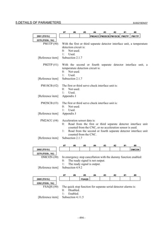
![B-65270EN/07 3. αiS/αiF/βiS SERIES PARAMETER ADJUSTMENT
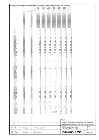
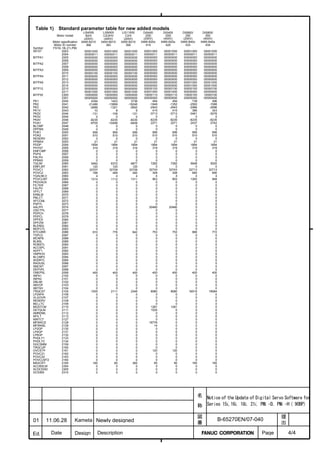
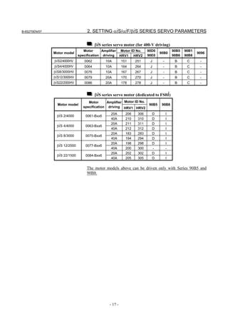
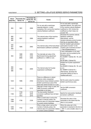
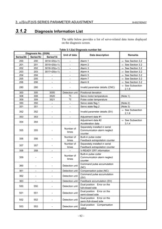
Table 3.1 Correspondence between the servo tuning screen and diagnosis screen, and parameters
Series 15i Series 30i, 16i, and so on
<1> Function bit No. 1808 No. 2003
<2> Loop gain No. 1825 No. 1825
<3> Tuning start bit Not used at present
<4> Setting period Not used at present
<5> Velocity loop integral gain No. 1855 No. 2043
<6> Velocity loop proportional gain No. 1856 No. 2044
<7> TCMD filter No. 1857 No. 2067
Related to No. 1875 Related to No. 2021
The relationship with the load inertia ratio (LDINT=No.1875,No.2021) is as
<8> Velocity loop gain
follows:
Velocity gain = (1 + LDINT/256) × 100 [%]
<9> Alarm 1 diagnosis Diagnosis Nos. 3014 + 20(X - 1) Diagnosis No. 200
<10> Alarm 2 Diagnosis Nos. 3015 + 20(X - 1) Diagnosis No. 201
<11> Alarm 3 Diagnosis Nos. 3016 + 20(X - 1) Diagnosis No. 202
<12> Alarm 4 Diagnosis Nos. 3017 + 20(X - 1) Diagnosis No. 203
<13> Alarm 5 __________ Diagnosis No. 204
<19> Alarm 6 __________ __________
<20> Alarm 7 __________ Diagnosis No. 205
<21> Alarm 8 __________ Diagnosis No. 206
<22> Alarm 9 __________ __________
<14> Loop gain or actual loop gain The actual servo loop gain is displayed.
Diagnosis No. 3000 Diagnosis No. 300
<15> Position error diagnosis Position error =
(feedrate) [mm/min] / (least input increment × 60 × loop gain × 0.01) [mm]
<16> Actual current [%] Indicates the percentage [%] of the current value to the continuous rated
current.
<17> Actual current [Ap] Indicates the current value (peak value).
<18> Actual speed [min-1] or [mm/min] Indicates the actual speed or feedrate.
- 81 -](https://image.slidesharecdn.com/b-65270en07-121129013640-phpapp01/85/B-65270-en-07-91-320.jpg)
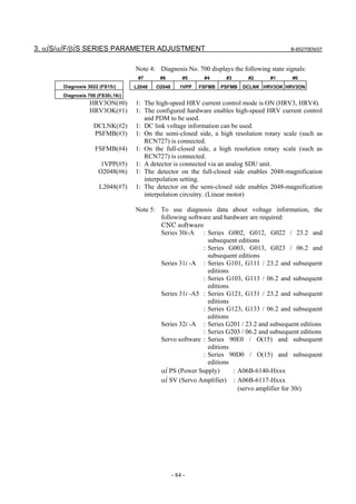
![B-65270EN/07 3. αiS/αiF/βiS SERIES PARAMETER ADJUSTMENT
Diagnosis no. (DGN)
Unit of data Data description Remarks
Series30i Series16i Series15i
700 700 3022 - Servo state flag 3 (Note 4)
750 - 3540 % OVC data Alarm with 100%
752 - - Vrms Voltage information (Note 5)
Imax=Maximum
760 - - Imax[Ap]/6554 R phase current value
amplifier current
Imax=Maximum
761 - - Imax[Ap]/8027 Effective current value
amplifier current
762 - - 360[deg]/256 Excitation phase data
Note 1: When a linear motor or synchronous built-in servo motor is
used and temperature information (thermistor signal) is
connected to a temperature detection circuit, αiCZ detection
circuit, or linear motor detection circuit, the temperature of
the motor can be displayed on diagnosis No. 308.
⇒ See the following subsections:
2.1.7 Setting Parameters When an Acceleration Sensor or
Temperature Detection Circuit Is Used
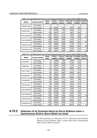
4.14.2 Detection of an Overheat Alarm by Servo Software
when a Linear Motor and a Synchronous Built-in
Servo Motor are Used
Note 2: Diagnosis No. 350 displays the following state signals:
#7 #6 #5 #4 #3 #2 #1 #0
- ALMTMP ALMACC A_PHAL PM0CHK PM0TMP PM0ACC PM0POS
Diagnosis 350 (FS30i,16i)
PM0POS(#0) 1: A position detector is connected to the first SDU unit.
PM0ACC(#1) 1: An acceleration sensor is connected to the first SDU unit.
PM0TMP(#2) 1: A temperature detection circuit is connected to the first SDU unit.
PM0CHK(#3) 1: A servo check interface unit is connected to the first SDU unit.
A_PHAL(#4) 1: An error has occurred in the EEPROM of the αi pulse coder.
(This is not an alarm.)
ALMACC(#5) 1: An alarm is issued from an acceleration sensor.
ALMTMP(#6) 1: An alarm is issued from a temperature detection circuit.
Note 3: Diagnosis No. 351 displays the following state signals:
#7 #6 #5 #4 #3 #2 #1 #0
- PM1CHK PM1TMP PM1ACC PM1POS
Diagnosis 351 (FS30i,16i)
PM1POS(#0) 1: A position detector is connected to the second SDU unit.
PM1ACC(#1) 1: An acceleration sensor is connected to the second SDU unit.
PM1TMP(#2) 1: A temperature detection circuit is connected to the second SDU
unit.
PM1CHK(#3) 1: A servo check interface unit is connected to the second SDU unit.
- 83 -](https://image.slidesharecdn.com/b-65270en07-121129013640-phpapp01/85/B-65270-en-07-93-320.jpg)
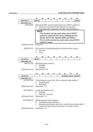
![3. αiS/αiF/βiS SERIES PARAMETER ADJUSTMENT B-65270EN/07
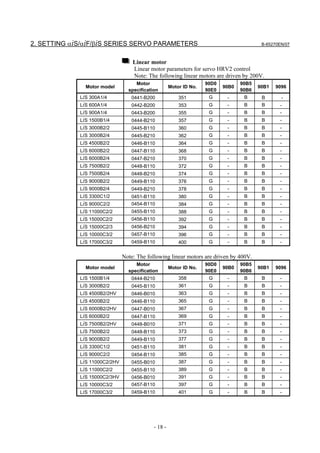
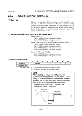
3.1.4 Acceleration Monitor Function
(1) Overview
Width the acceleration monitor function, acceleration feedback can be
observed on diagnosis screen No. 354.
(2) Series and editions of applicable servo software
(Series 30i,31i,32i)
Series 90D0/P(16) and subsequent editions
Series 90E0/P(16) and subsequent editions
(Series 16i-B,18i-B,21i-B,0i-B,0i Mate-B,Power Mate i)
Series 90B1/I(09) and subsequent editions (*1)
(Series 0i-C,0i Mate-C)
Series 90B8/I(09) and subsequent editions (*1)
(*1) Series 90B1 and 90B8 do not support the function (bit 2 of No.
2290) for output of remaining acceleration data.
(3) Setting parameters
By setting bit 0 of No. 2290 to 1 after setting an acceleration sensor
(Subsection 2.1.7), acceleration feedback can be displayed on
diagnosis screen No. 354.
By setting bit 1 of No. 2290 to 1, a peak acceleration rate can be held
(for 1 second). By setting bit 2 of No. 2290 to 1, the remaining
acceleration data after a stop can be observed.
#7 #6 #5 #4 #3 #2 #1 #0
- ACCMON ACCHLD ACCOUT
2290(FS30i,16i)
ACCOUT(#0) To the diagnosis screen (No. 354), acceleration data output is:
0: Not performed.
1: Performed.
ACCHLD(#1) A peak acceleration rate is:
0: Not held.
1: Held (for 1 second).
ACCMON(#2) 0: Acceleration data is output at all times.
1: The remaining acceleration data after a stop is output. (The
acceleration data is cleared to 0 during movement and for 16 ms
after a stop.)
- Acceleration feedback
Diagnosis 354 (FS30i,16i)
[Display unit] mm/s2
- 86 -](https://image.slidesharecdn.com/b-65270en07-121129013640-phpapp01/85/B-65270-en-07-96-320.jpg)
![B-65270EN/07 3. αiS/αiF/βiS SERIES PARAMETER ADJUSTMENT
1971 (FS15i) Dual position feedback conversion coefficient (numerator)
2078 (FS30i, 16i)
1972 (FS15i) Dual position feedback conversion coefficient (denominator)
2079 (FS30i, 16i)
Number of feedback pulses per
motor revolution (detection unit)
Conversion coefficient =
1,000,000
1729 (FS15i) Dual position feedback semi-closed loop error level
2118 (FS30i, 16i)
[Setting unit] Detection unit. When 0 is set, detection does not take place.
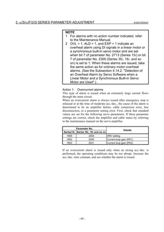
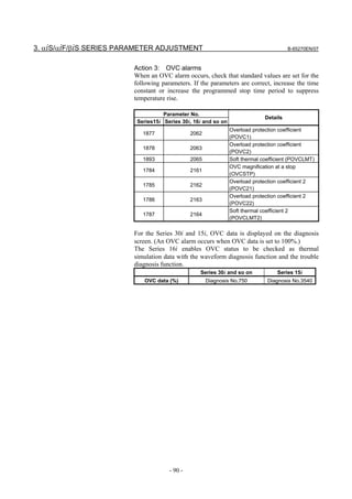
Action 3: The current offset (equivalent to the current value in the
emergency stop state) of the current detector becomes too
large. If the alarm occurs again after the power is turned on
and off, the current detector may be abnormal. Replace the
amplifier.
- 95 -](https://image.slidesharecdn.com/b-65270en07-121129013640-phpapp01/85/B-65270-en-07-105-320.jpg)
![3. αiS/αiF/βiS SERIES PARAMETER ADJUSTMENT B-65270EN/07
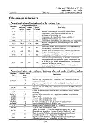
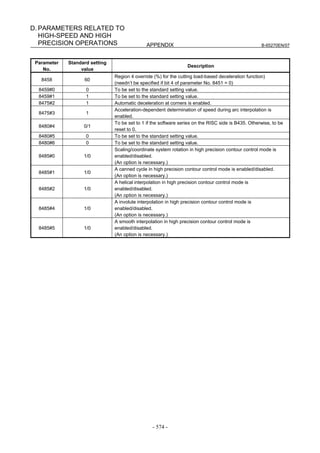
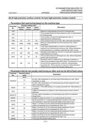
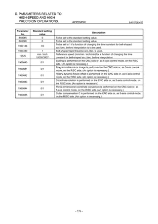
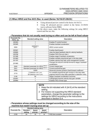
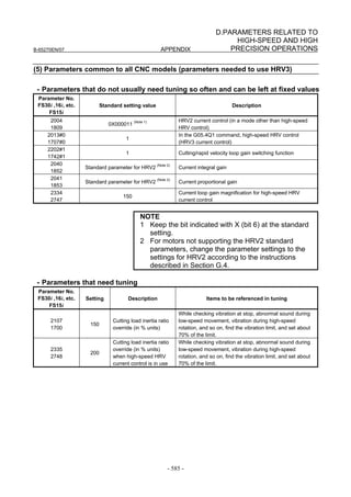
(3) Initialization of parameters related to high-speed and high-precision
machining
The parameter values to be set first before servo adjustments are made
are listed below. Sufficient performance can be obtained just by
setting these values. Furthermore, by separately adjusting the settings
indicated by gray shading, much higher speed and higher precision
can be obtained.
[Fundamental Parameters]
Parameter No.
Standard setting value Description
FS15i FS30i, 16i, and so on
1809 2004 0X000011 (Note 1) Enables HRV2 control
1852 2040 Standard parameter (Note 1) Current integral gain
1853 2041 Standard parameter (Note 1) Current proportional gain
1808 #3 2003 #3 1 (Note 2) Enables PI function
1959 #7 2017 #7 1 (Note 3) Enables velocity loop high cycle management function
1884 #4 2006 #4 1 Enables 1-ms velocity feedback acquisition
1958 #3 2016 #3 1 Enables variable proportional gain in the stop state
For variable proportional gain function in the stop state :
2 (detection unit of 1 µm)
1730 2119 judgment level for stop state
20 (detection unit of 0.1µm)
(specified in detection units)
1825 1825 5000 Servo loop gain
1875 2021 128 Load Inertia ratio (Velocity Loop Gain) (Note 4)
1742 #1 2202 #1 1 Cutting/rapid traverse velocity loop gain variable
1700 2107 150 Velocity loop gain override at cutting traverse
NOTE
1 Optimum parameters can be loaded automatically by setting a motor ID number for
servo HRV2 control.
If there is no motor ID number for servo HRV2 control, load the standard
parameters for servo HRV1, then calculate parameter values as follows:
No. 2004 = 0X000011 (Keep X unchanged.)
No. 2040 = Standard parameter for HRV1 × 0.8
No. 2041 = Standard parameter for HRV1 × 1.6
2 To use I-P function, set 0.
PI function and I-P function have the following features:
PI function: Provides good follow-up to a target command. This function is required
for high-speed and high-precision machining.
I-P function: Requires a relatively short time to attain a target position. This function
is suitable for positioning applications.
3 With some machines, a higher velocity loop gain can be set by using neither the
acceleration feedback function nor auxiliary function rather than by using these
functions. If it is impossible to set a high velocity loop gain (about 300%) when the
velocity loop high cycle management function is used, try to use the acceleration
feedback function (See Subsection 4.4.2), and use the function that allows a higher
velocity loop gain to be set.
4 There is the following relationship between the load inertia ratio and velocity loop
gain (%).
Velocity loop gain (%) = (1 + load inertia ratio / 256) × 100
- 98 -](https://image.slidesharecdn.com/b-65270en07-121129013640-phpapp01/85/B-65270-en-07-108-320.jpg)
![B-65270EN/07 3. αiS/αiF/βiS SERIES PARAMETER ADJUSTMENT
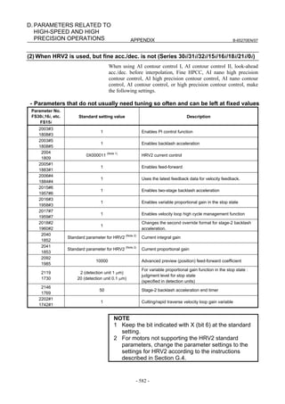
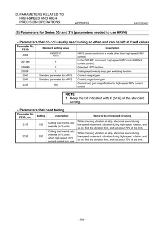
[Feed-forward and FAD(Fine acc./dec.)]
Parameter No.
Standard setting
FS30i, 16i, Description
FS15i value
and so on
1951 #6 2007 #6 1 Enables FAD (Fine acc./dec.) (Note 1)
1749 #2 2209 #2 1 Enables FAD of linear type.
1702 2109 16 FAD time constant (Note 2)
1883 #1 2005 #1 1 Enables feed-forward
1800 #3 1800 #3 0 Feed-forward at rapid traverse (Note 2)
1959 #5 2017 #5 1 RISC feed-forward is improved
1740 #5 2200 #5 1 RISC feed-forward is improved
1985 2092 10000 Advanced preview feed-forward coefficient
1962 2069 50 Velocity feed-forward coefficient
NOTE
1 With the Series 30i, Series 31i, and Series 32i, which use nano interpolation
as a standard function, the fine acc./dec. function is not required.
During AI nano contour control, AI contour control, and high precision
contour control, the fine acc./dec. function is disabled. So, set the time
constant of acc./dec. after interpolation on the CNC side.
2 As the time constant of fine acc./dec., be sure to set a multiple of 8.
When using fine Acc./Dec also in rapid traverse, enable rapid traverse
feed-forward, or use the cutting/rapid FAD switching function (see
Subsection 4.8.3).
3 RISC feed-forward is enabled during AI contour control and high precision
contour control and allows smoother feed-forward operation.
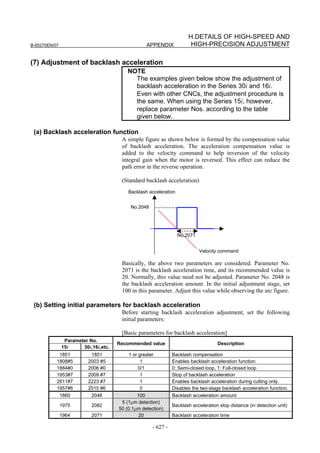
[Backlash Acceleration]
Parameter No.
FS30i, 16i, Standard setting value Description
FS15i
and so on
1851 1851 1 or more Backlash compensation
1808 #5 2003 #5 1 Enables backlash acceleration
0 : Semi-close system
1884 #0 2006 #0 0/1
1 : Full-close system
1953 #7 2009 #7 1 Backlash acceleration stop
1953 #6 2009 #6 1 Backlash acceleration only at cutting feed (FF)
2611 #7 2223 #7 1 Backlash acceleration only at cutting feed (G01)
1957 #6 2015 #6 0 Two-stage backlash acceleration (Note)
1769 2146 50 Two-stage backlash acceleration end timer
1860 2048 100 Backlash acceleration amount
5 (detection unit of 1 µm)
1975 2082 Backlash acceleration stop timing
50 (detection unit of 0.1 µm)
1964 2071 20 Backlash acceleration time
NOTE
The above table lists the initial values set when the conventional backlash
acceleration function is used. When much higher precision is required, use
the two-stage backlash acceleration function.
- 99 -](https://image.slidesharecdn.com/b-65270en07-121129013640-phpapp01/85/B-65270-en-07-109-320.jpg)
![3. αiS/αiF/βiS SERIES PARAMETER ADJUSTMENT B-65270EN/07
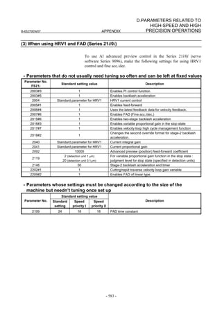
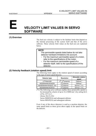
[Time Constant]
Set the initial value of the time constant of acc./dec. according to the
high-speed and high-precision function of the CNC used. Adjust the
time constant of acc./dec. to an optimum value while checking the
rapid traverse and cutting feed operations.
• AI nano contour control, AI contour control, AI advanced
preview control, and advanced preview control
Parameter No. Standard
Description
FS16i and so on setting value
1620 200 Time constant of acc./dec. in rapid traverse - linear part (ms)
1621 200 Time constant of acc./dec. in rapid traverse - bell-shaped part (ms)
1770 10000 Acc./dec. before interpolation: Maximum cutting feedrate
1771 240 Acc./dec. before interpolation: Time (ms) 0.07G
Acc./dec. before interpolation: Bell-shaped time constant (ms) (for other than
1772 64
advanced preview control)
1768 24 Time constant for acc./dec. after interpolation (ms)
• AI nano high-precision contour control, AI high-precision
contour control, and high-precision contour control
Parameter No. Standard
Description
FS16i and so on setting value
1620 200 Time constant of acc./dec. in rapid traverse - linear part (ms)
1621 200 Time constant of acc./dec. in rapid traverse - bell-shaped part (ms)
8400 10000 Acc./dec. before interpolation: Maximum cutting feedrate
Acc./dec. before interpolation: Time (ms) 0.07G (No. 8401 for high precision
19510 240
contour control)
8416 64 Acc./dec. before interpolation: Bell-shaped time constant (ms)
1768 24 Time constant for acc./dec. after interpolation (ms)
• AI contour control I and AI contour control II (Series 30i, Series
31i, and Series 32i)
Parameter No. Standard
Description
FS30i setting value
1620 200 Time constant of acc./dec. in rapid traverse - linear part (ms)
1621 200 Time constant of acc./dec. in rapid traverse - bell-shaped part (ms)
1660 700 Acc./dec. before interpolation: Acceleration(mm/s2) 0.07G
1772 64 Acc./dec. before interpolation: Bell-shaped time constant (ms)
1769 24 Time constant for Acc./dec. after interpolation (ms)
• Series 15i
Parameter No. Standard
Description
FS15i setting value
1620 200 Time constant of Acc./dec. in rapid traverse - linear part (ms)
1636 200 Time constant of Acc./dec. in rapid traverse - bell-shaped part (ms)
1660 700 Acc./dec. before interpolation: Acceleration(mm/s2) 0.07G
Permissible acceleration in velocity reduction based on acceleration (HPCC mode)
1663 700
(mm/s2)
1656 64 Acc./dec. before interpolation: Bell-shaped time constant (ms)
1635 24 Time constant for acc./dec. after interpolation (ms)
- 100 -](https://image.slidesharecdn.com/b-65270en07-121129013640-phpapp01/85/B-65270-en-07-110-320.jpg)
![B-65270EN/07 3. αiS/αiF/βiS SERIES PARAMETER ADJUSTMENT
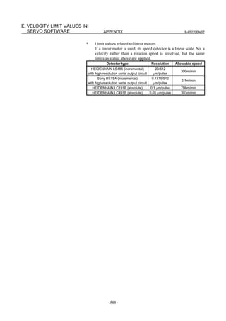
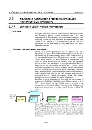
(4) Servo HRV control setting
Set the type of servo HRV control. The setting of servo HRV2 is
always required. So, load the standard parameters for servo HRV2 by
following the description given below. Then, set HRV3 or HRV4 as
necessary.
(For Series 30i)
In standard setting, servo HRV2 control is set. However, to make
high-speed and high-precision adjustments, servo HRV3 is
recommended. If sufficient precision cannot be obtained with
servo HRV3, consider using servo HRV4. (See Subsec. 4.2.2.)
(For other than Series 30i)
In standard setting, servo HRV2 control is set. However, if
sufficient precision cannot be obtained with servo HRV2,
consider using servo HRV3. (See Subsec. 4.2.1.)
(a) Servo HRV2 control
By setting a motor ID number for servo HRV2 control, load the
standard parameters.
NOTE
If there is no motor ID number for servo HRV2
control, load the standard parameters for servo
HRV1, then calculate parameter values as follows:
No. 2004 = 0X000011 (Keep X unchanged.)
No. 2040 = Standard parameter for HRV1 × 0.8
No. 2041 = Standard parameter for HRV1 × 1.6
(b) Servo HRV3 control
After setting servo HRV2 control, set the following parameters:
[HRV3 parameters] (for FS15i, FS16i, and so on)
Parameter No. Recommended
Description
FS15i FS16i value
1707#0 2013#0 1 Enables HRV3 current control.
Enables the cutting/rapid velocity loop
1742#1 2202#1 1
gain switching function.
Enables high-speed HRV current control
- 2283#0 1
in cutting feed (Note 1).
2747 2334 150 Current gain magnification in HRV3 mode
2748 2335 200 Velocity gain magnification in HRV3 mode
NOTE
1 To use high-speed HRV current control, G codes need
to be set. (High-speed HRV current control is enabled
between G5.4Q1 and G5.4Q0.)
2 With Series 90B0, 90B1, 90B5, 90B6, and 90B8, the
torque command during high-speed HRV current control
is limited to 70% of the maximum value.
- 101 -](https://image.slidesharecdn.com/b-65270en07-121129013640-phpapp01/85/B-65270-en-07-111-320.jpg)
![3. αiS/αiF/βiS SERIES PARAMETER ADJUSTMENT B-65270EN/07
[HRV3 parameters] (for FS30i)
Parameter No. Recommended
Description
FS30i value
2013#0 1 Enables HRV3 current control.
Enables the cutting/rapid velocity loop
2202#1 1
gain switching function.
2334 150 Current gain magnification in HRV3 mode
2335 200 Velocity gain magnification in HRV3 mode
NOTE
1 When N2283#0=1, no G code is needed.
2 To use high-speed HRV current control when
N2283#0=0, G codes need to be set. (High-speed HRV
current control is enabled between G5.4Q1 and
G5.4Q0.)
3 Series 90E0 imposes such a restriction that when servo
HRV3 control is used, the maximum number of axes per
servo card decreases.
(c) Servo HRV4 control
After setting servo HRV2 control, set the parameters listed below.
Servo HRV4 control and servo HRV3 control cannot be set at the
same time.
[HRV4 parameters]
Parameter No. Recommended
Description
FS30i value
2014#0 1 Enables HRV4 current control.
2300#0 1 Enables the extended HRV function.
Enables the cutting/rapid velocity loop
2202#1 1
gain switching function.
Current gain magnification in high-speed
2334 150
HRV current control
Velocity gain magnification in high-speed
2335 200
HRV current control
NOTE
1 Servo HRV4 can be used with Series 90D0.
2 Use of servo HRV4 decreases the maximum
number of axes per servo card and limits the
maximum torque of the servo motor to 70%. For
details, see Subsection 4.2.2, "Servo HRVV4
Control".
3 To use high-speed HRV current control, G codes
must be set. (High-speed HRV current control is
enabled between G5.4Q1 and G5.4Q0.)
- 102 -](https://image.slidesharecdn.com/b-65270en07-121129013640-phpapp01/85/B-65270-en-07-112-320.jpg)
![B-65270EN/07 3. αiS/αiF/βiS SERIES PARAMETER ADJUSTMENT
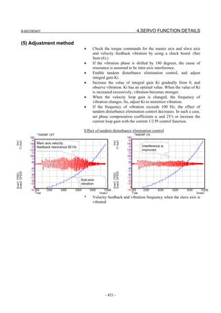
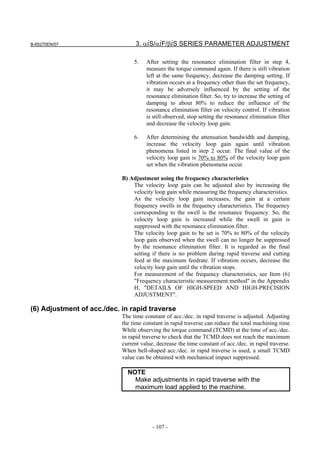
(5) Adjustment of high-speed velocity control
After setting servo HRV control, adjust the velocity loop gain and the
resonance elimination filter.
To obtain high servo performance, a high velocity loop gain must be
set. Some machines, however, vibrate easily at a particular frequency,
and setting a high velocity loop gain can cause vibration at that
frequency (machine resonance). As a result, it becomes impossible to
set a high velocity loop gain.
In such a case, the resonance elimination filter must be adjusted. The
resonance elimination filter can lower the gain only in an area around
a particular frequency, therefore allowing a high velocity loop gain to
be set without the occurrence of machine resonance.
The velocity loop gain and the resonance elimination filter can be
adjusted more easily by using Tuning Navigator of SERVO GUIDE.
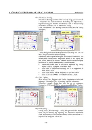
(a) Adjusting the velocity loop gain and the resonance elimination filter (when
Tuning Navigator is used)
For adjustment of the resonance elimination filter, Tuning Navigator
of SERVO GUIDE can be used. On the main bar of SERVO GUIDE,
press the [Navigator] button.
[Starting Tuning Navigator]
Clicking this button displays the menu as shown below.
<1>
<2>
<3>
(Procedure for adjusting the velocity loop gain and the resonance
elimination filter)
In the adjustment of the velocity loop gain and the resonance
elimination filter, use <1> through <3> in the above figure. Make
adjustments in order from <1>.
- 103 -](https://image.slidesharecdn.com/b-65270en07-121129013640-phpapp01/85/B-65270-en-07-113-320.jpg)
![B-65270EN/07 3. αiS/αiF/βiS SERIES PARAMETER ADJUSTMENT
(b) Adjusting the velocity loop gain and the resonance elimination filter (when
Tuning Navigator is not used)
A)Adjustment by torque command waveform
1. Perform rapid traverse with a full stroke of the machine, and
observe the torque command when the machine is stopped
and when the machine moves at high speed. (The sampling
cycle period should be 125 µs.)
NOTE
When using the cutting/rapid velocity loop gain
switching function, perform cutting feed at the
maximum cutting feedrate to also check the
cutting-time oscillation limit.
2. As the velocity loop gain is increased gradually, the
following oscillation phenomena occur:
• Vibration occurs in the torque command waveform.
• Vibration sound is generated from the machine.
• A large variation in positional deviation is observed
when the machine movement stops.
3. Perform frequency analysis (Ctrl-F) for the torque
command issued when the above phenomena occur, and
measure the vibration frequency.
4. Set the measured vibration frequency as the attenuation
center frequency, and set the initial values of the attenuation
bandwidth and damping by consulting the setting guideline.
[Setting guideline]
Resonance frequency Attenuation bandwidth Damping
(Note 3)
Lower than 150 Hz Decrease the velocity loop gain.
(Note 3)
150 to 200 Hz Decrease the velocity loop gain.
200 to 400 Hz 60 to 100Hz 0 to 50%
Higher than 400 Hz 100 to 200Hz 0 to 10%
[Parameter Nos.]
Attenuation
Attenuation
center Damping
Series 30i, 16i bandwidth
frequency [%]
[Hz]
[Hz]
Resonance elimination filter 2 No.2360 No.2361 No.2362
Resonance elimination filter 3 No.2363 No.2364 No.2365
Resonance elimination filter 4 No.2366 No.2367 No.2368
Resonance elimination filter 1 No.2113 No.2177 No.2359
Attenuation
Attenuation
center Damping
Series 15i bandwidth
frequency [%]
[Hz]
[Hz]
Resonance elimination filter 2 No.2773 No.2774 No.2775
Resonance elimination filter 3 No.2776 No.2777 No.2778
Resonance elimination filter 4 No.2779 No.2780 No.2781
Resonance elimination filter 1 No.1706 No.2620 No.2772
- 105 -](https://image.slidesharecdn.com/b-65270en07-121129013640-phpapp01/85/B-65270-en-07-115-320.jpg)
![3. αiS/αiF/βiS SERIES PARAMETER ADJUSTMENT B-65270EN/07
NOTE
1 The disturbance elimination filter (see Subsection
4.5.4) may be effective.
2 When the resonance elimination filter is used, set a
narrow attenuation bandwidth (about 50 Hz or less)
and a large damping attenuation factor (about 50%
to 80%).
3 When the center frequency becomes 200 Hz or
lower, almost the same effect as when the velocity
loop gain is decreased is obtained. Since the
resonance elimination filter also has the effect in
the change of phase, decreasing the velocity loop
gain is recommended.
4 The resonance elimination filter becomes more
effective as damping becomes closer to 0%.
Therefore, when adjusting damping, start with a
large value and decrease it gradually.
When SERVO GUIDE can be used, the resonance elimination filter
can be set from the parameter window.
[Starting the parameter window]
Clicking this button displays the parameter window.
[Parameter window main screen] [Velocity control + filter]
- 106 -](https://image.slidesharecdn.com/b-65270en07-121129013640-phpapp01/85/B-65270-en-07-116-320.jpg)
![B-65270EN/07 3. αiS/αiF/βiS SERIES PARAMETER ADJUSTMENT
[Parameter window main screen] [Acc./dec. + normal control]
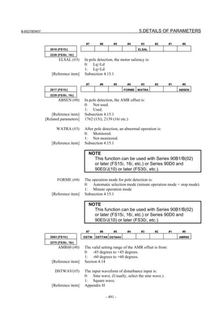
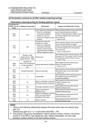
(7) Adjustment of the position gain
Observe the torque command waveform at the time of acc./dec. during
rapid traverse and cutting feed at the maximum cutting feedrate. When
a low frequency vibration (hunting) of about 10 to 30 Hz occurs in the
torque command waveform, the corresponding position gain is
regarded as the oscillation limit. The position gain to be set is about
80% of the position gain of the oscillation limit.
The standard setting is within 5000 to 10000.
<3> Feedrate <4> <5>
<2>
<1> TCMD
<3> <4> <5> <7>
<2>
(Check points)
• No vibration is allowed in the stopped state. Also check the
positional deviation on the CNC. (<1>)
• Neither vibration nor sound must be generated during
acceleration and deceleration. If the TCMD level has reached the
maximum value, increase rapid traverse acc./dec. time constant
T1. (<2>, <5>)
• Neither vibration nor excessive overshoot must be generated at
the end of acceleration and deceleration. If the TCMD level has
reached the maximum value, increase rapid traverse acc./dec.
time constant T2. (<3>, <7>)
• There must be no large variation in feedrate during movement at
a constant feedrate. (<4>)
- 109 -](https://image.slidesharecdn.com/b-65270en07-121129013640-phpapp01/85/B-65270-en-07-119-320.jpg)
![3. αiS/αiF/βiS SERIES PARAMETER ADJUSTMENT B-65270EN/07
NOTE
For axes for which interpolation is performed, set
the same position gain.
[Parameter window main screen] [Position control]
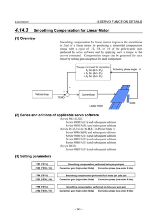
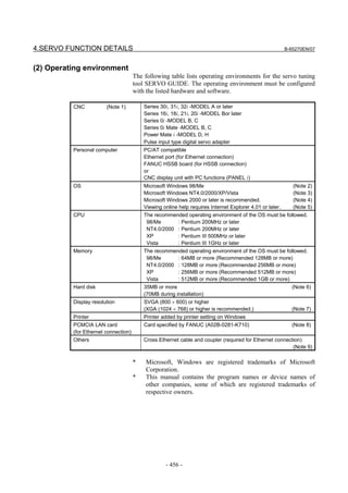
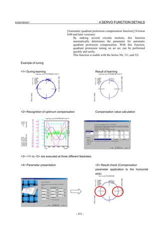
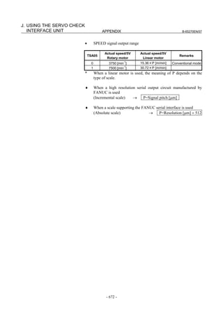
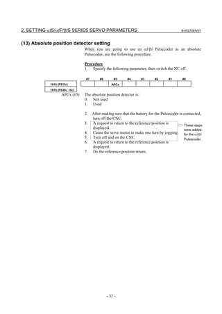
(8) Adjustment by using an arc (adjustment of the feed-forward coefficient
and adjustment of the servo function)
(a) Feed-forward function
For higher precision with small servo follow-up delay, the
feed-forward function is used. When the feed-forward coefficient is
set to 100%, the positional deviation can be almost eliminated.
(Feed-forward)
By adding to a velocity command value the velocity
compensation value equivalent to the position command issued
from the CNC, the contour error due to position loop response
delay can be reduced.
(Velocity feed-forward)
The torque compensation amount equivalent to the amount of
change in velocity command (acceleration) is added to a
specified torque value so that the contour error due to velocity
loop response delay can be reduced.
Velocity
Feed-forward
feed-forward
Velocity compensation Torque
+ amount + compensation
+ + Velocity control +
Position control
Position Velocity Current
-
command command command
Position feedback
- 110 -](https://image.slidesharecdn.com/b-65270en07-121129013640-phpapp01/85/B-65270-en-07-120-320.jpg)
![B-65270EN/07 3. αiS/αiF/βiS SERIES PARAMETER ADJUSTMENT
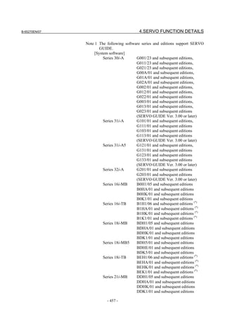
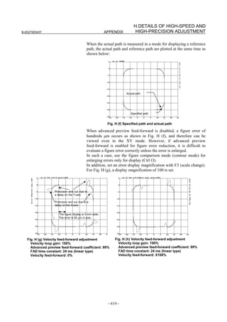
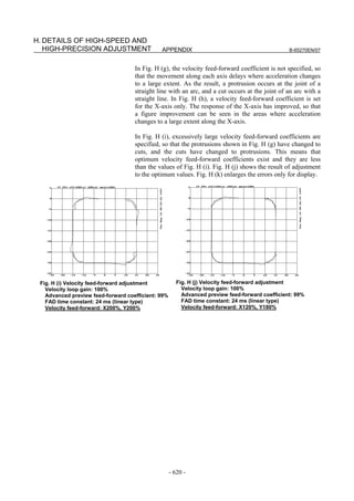
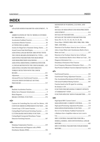
The following figure shows the effect of the feed-forward function.
The figure indicates that an arc radius error of 250 µm, which was
measured before the use of the feed-forward function, has been
reduced to almost 0 after the use of the feed-forward function.
Feed-forward coefficient 0% Feed-forward coefficient 100%
Radius error is about Radius error is
250 µm almost 0 µm
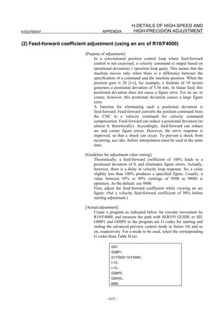
(b) Adjusting the feed-forward coefficient
The feed-forward coefficient can be adjusted on the screen shown
below. Note that, however, setting the feed-forward coefficient to
more than 10000 (100%) means that the actual machine position
advances ahead of commands from the CNC. So, such setting is not
permitted.
[Parameter window main screen] [Contour error suppression + feed-forward]
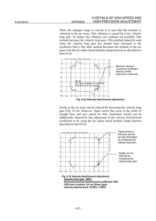
While checking fluctuation of radius by using an arc with about
R10/F4000 or R100/F10000 set, make an adjustment so that the actual
path matches the commanded path. At this time set the velocity
feed-forward coefficient to about 100.
NOTE
To fine-tune the amount of arc radius, also adjust
the feed-forward timing parameter after adjusting
the feed-forward coefficient. (See Subsection
4.6.5.)
- 111 -](https://image.slidesharecdn.com/b-65270en07-121129013640-phpapp01/85/B-65270-en-07-121-320.jpg)
![3. αiS/αiF/βiS SERIES PARAMETER ADJUSTMENT B-65270EN/07
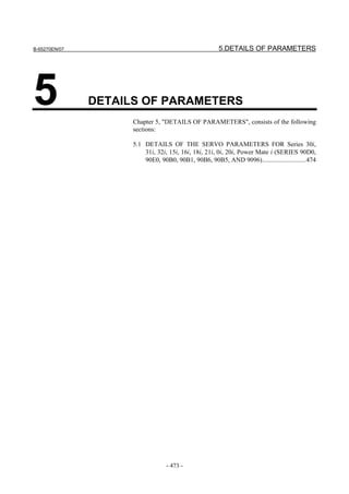
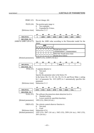
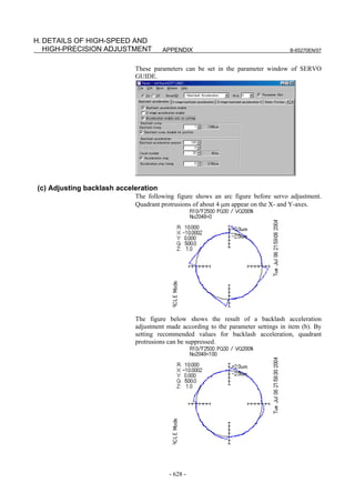
(c) Adjusting backlash acceleration
To reduce quadrant protrusions (errors generated where the axis move
direction is reversed), the backlash acceleration function is used.
While observing the quadrant protrusion size, change the backlash
acceleration value in steps of about 10 to 20, and ends the adjustment
immediately before undercut occurs. A large quadrant protrusion or
undercut may adversely affect cutting results. So, adjust the backlash
acceleration so that any quadrant protrusion is not greater than 5 µm.
NOTE
1 For the adjustment of the conventional backlash
acceleration function, see Subsection 4.6.6.
2 When higher precision is required, use the 2-stage
backlash acceleration function (see Subsection
4.6.7).
[Parameter window main screen] [Contour error suppression + backlash acceleration]
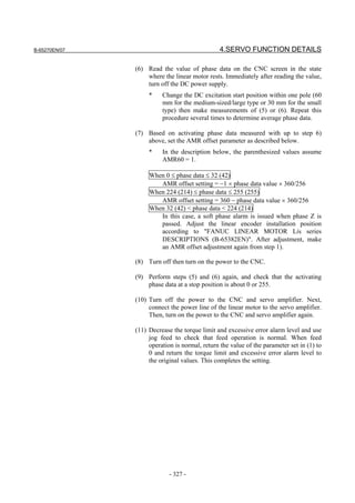
- 112 -](https://image.slidesharecdn.com/b-65270en07-121129013640-phpapp01/85/B-65270-en-07-122-320.jpg)
![B-65270EN/07 3. αiS/αiF/βiS SERIES PARAMETER ADJUSTMENT
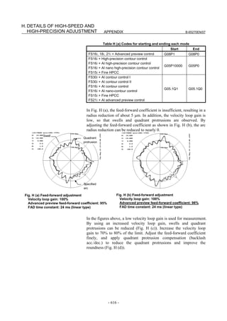
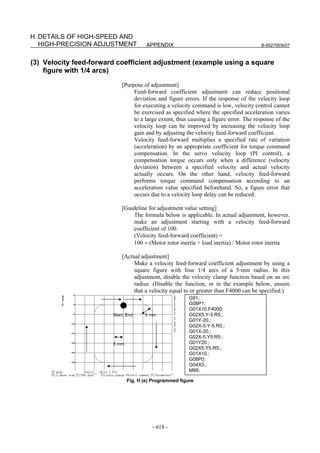
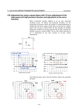
(9) Adjustment by using a square figure (adjustment of the high-speed and
high-precision function and adjustment of the servo function)
(a) Setting the corner deceleration function
When the automatic corner deceleration function is used, an error at
the corner (overshoot) can be reduced. First, set the reduced corner
feedrate to 400 mm/min.
[Parameter window main screen] [Acc./dec. + AI contour control 2 (when AI contour
control II is used)]
The figure below shows the effect of the corner deceleration function.
Deceleration at a corner reduces the amount of the overshoot.
20µm 20µm
Axis Axis
movement movement
NOTE
For fine-adjustment of a corner overshoot, the
following parameters are also related:
• Acc./dec. before interpolation
• Velocity feed-forward coefficient
- 113 -](https://image.slidesharecdn.com/b-65270en07-121129013640-phpapp01/85/B-65270-en-07-123-320.jpg)
![3. αiS/αiF/βiS SERIES PARAMETER ADJUSTMENT B-65270EN/07
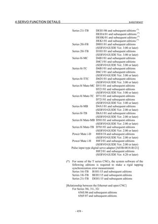
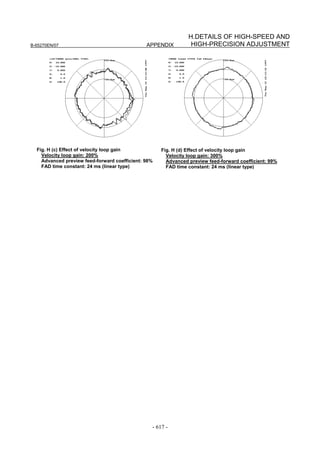
(b) Adjusting the time constant in cutting feed
In automatic corner deceleration, the feedrate at which the tool moves
along a corner is reduced according to the permissible acceleration set
for acc./dec. before interpolation. When the automatic corner
deceleration function is used, the tangential feedrate at the corner
changes in a V-shaped manner as shown below. As the permissible
acceleration for acc./dec. before interpolation is decreased,
deceleration at the corner becomes smoother, therefore, the contour
error at the corner can be decreased.
D A
Y
Position path
X
C B
Linear part
F3000 Feedrate along X-axis
F3000
A B C D
A B C D
Feedrate along Y-axis
Corner: F500
Tangential feedrate indication Indication of feedrate along each axis
[Parameter window main screen] [Acc./dec. + AI contour control 2 (when AI
contour control II is used)]
If the contour error at the corner cannot be reduced even by adjusting
the permissible feedrate difference, increase the time constant of
acc./dec. before interpolation.
When bell-shaped Acc/Dec. before interpolation is used, contour
errors not only at corners but also rounded corners may be improved.
Note that, however, a larger time constant extends the total machining
time.
- 114 -](https://image.slidesharecdn.com/b-65270en07-121129013640-phpapp01/85/B-65270-en-07-124-320.jpg)
![B-65270EN/07 3. αiS/αiF/βiS SERIES PARAMETER ADJUSTMENT
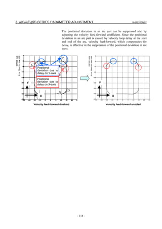
(c) Adjusting velocity feed-forward
The velocity feed-forward function has the effect of helping the torque
command start earlier at the time of acc./dec. This effect is reflected in
corner figures. So, adjust the velocity feed-forward coefficient so that
corner figures can be improved. When nano interpolation is not used,
set the coefficient value to 400 or smaller.
[Parameter window main screen] [Contour error suppression + feed-forward]
- 115 -](https://image.slidesharecdn.com/b-65270en07-121129013640-phpapp01/85/B-65270-en-07-125-320.jpg)
![B-65270EN/07 3. αiS/αiF/βiS SERIES PARAMETER ADJUSTMENT
[Parameter window main screen] [Acc./dec. + AI contour control 2 (when AI
contour control II is used)]
When advanced preview control is used, the feedrate at a rounded
portion is suppressed by setting the arc radius and feedrate. For
example, when the arc radius is 5 mm, and the feedrate is to be
decreased to F2000, set R to 5 mm, and the feedrate to F2000
mm/min.
[Parameter window main screen] [Acc./dec. + advanced preview control (when
advanced preview control is used)]
- 117 -](https://image.slidesharecdn.com/b-65270en07-121129013640-phpapp01/85/B-65270-en-07-127-320.jpg)
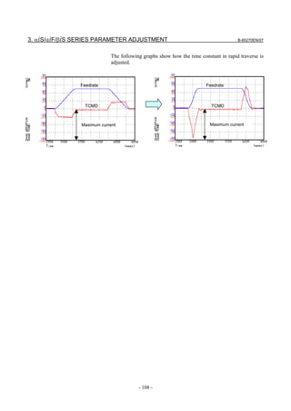
![3. αiS/αiF/βiS SERIES PARAMETER ADJUSTMENT B-65270EN/07
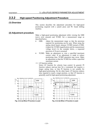
3.3.3 Rapid Traverse Positioning Adjustment Procedure
(1) Overview
The fine acc./dec. function applies a filter to each axis in the servo
software to reduce a shock associated with acc./dec. By combining the
fine acc./dec. function with feed-forward, high-speed positioning can
be achieved in rapid traverse. This section describes rapid traverse
positioning adjustment.
NOTE
1 With the Series 30i, smooth acc./dec. is performed
based on nano interpolation even during rapid
traverse, so that fine acc./dec. is unnecessary
(unusable). For adjustment, only rapid traverse
bell-shaped acc./dec. is used. With the Series 30i,
rapid traverse bell-shaped acc./dec. is a basic
function.
2 With the Series 16i and so forth, nano interpolation
is not applied during rapid traverse, so that the use
of fine acc./dec. for smoothing command execution
is effective. With the Series 16i, rapid traverse
bell-shaped acc./dec. is an optional function.
(2) High-speed positioning by a combination of fine acc./dec. and
feed-forward
(Rapid traverse positioning when fine acc./dec. is not used)
A servo loop not performing feed-forward has a delay equivalent to a
position loop gain. The time required for positioning after completion
of distribution from the CNC is four to five times the position gain
time constant (33 ms for 30 [1/s]) (133 to 165 ms for a position gain of
30). In normal rapid traverse, rapid traverse linear acc./dec. (Fig. 3.3.3
(a)) is used, so that acceleration changes to a large extent at the start
and end of acceleration. However, since feed-forward is not used,
acceleration change is made moderate by a position loop gain, and a
shock does not occur.
If a low linear acc./dec. time constant is set for high-speed positioning,
and a high position gain and feed-forward are set, the time required
for positioning is reduced, but a shock occurs. In this case, a shock can
be reduced by setting rapid traverse bell-shaped acc./dec. (Fig. 3.3.3
(a)).
- 122 -](https://image.slidesharecdn.com/b-65270en07-121129013640-phpapp01/85/B-65270-en-07-132-320.jpg)
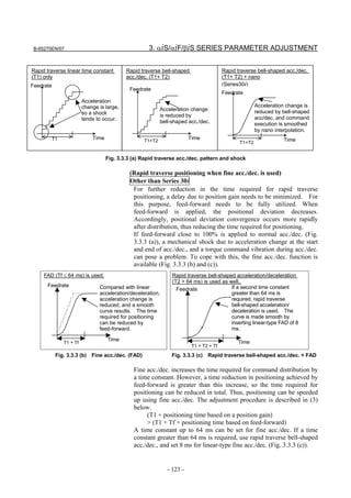
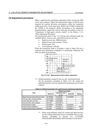
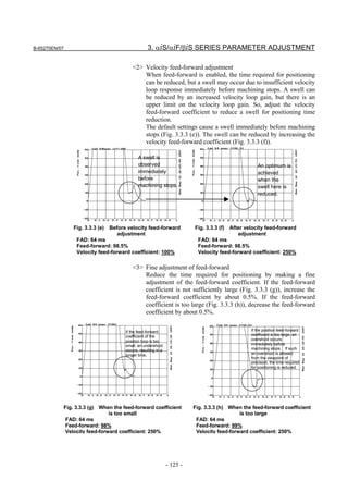

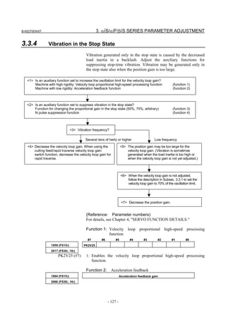
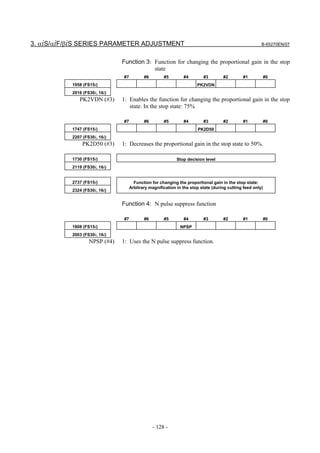
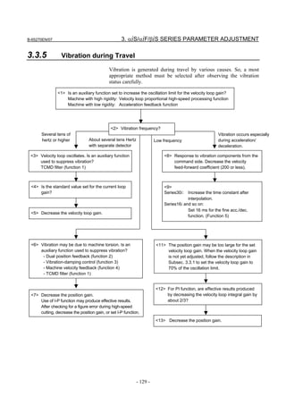
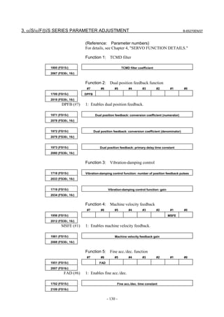
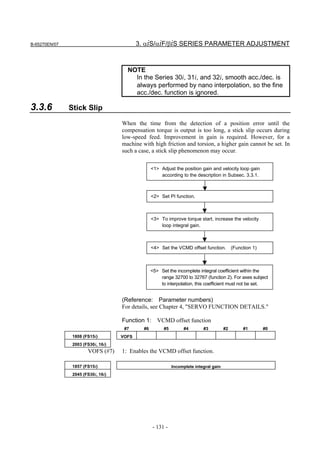
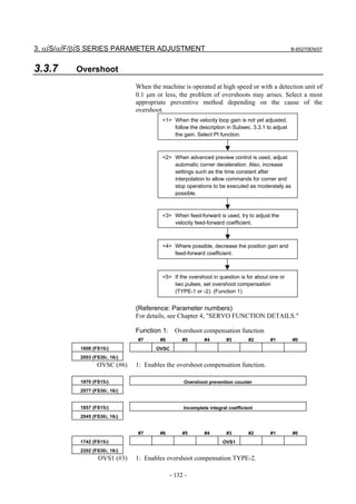
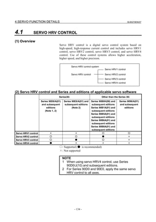
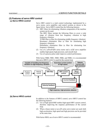

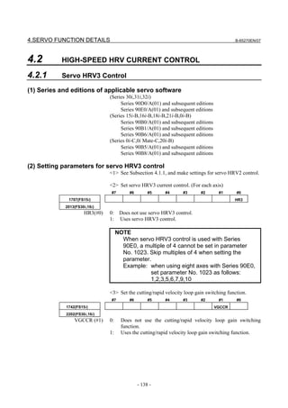
![B-65270EN/07 4.SERVO FUNCTION DETAILS
<4> Set the current loop gain magnification.
2747(FS15i) Current loop gain magnification in high-speed HRV current control mode
2334(FS30i,16i)
[Unit of data] %
[Valid data range] 100 to 270
[Recommended value] 150
This parameter is valid only for cutting feed in the high-speed HRV
current control mode.
<5> Set the velocity loop gain magnification.
2748(FS15i) Velocity loop gain magnification in high-speed HRV current control mode
2335(FS30i,16i)
[Unit of data] %
[Valid data range] 100 to 400
This parameter is valid only for cutting feed in the high-speed HRV
current control mode.
1700(FS15i) Velocity loop gain magnification for cutting (cutting/rapid velocity loop gain switching)
2107(FS30i,16i)
[Unit of data] %
[Valid data range] 100 to 400
This parameter is valid only for cutting feed when the high-speed
HRV current control mode is not set.
<6> Set the high-speed HRV current control mode.
To use servo HRV3 control with servo software Series 90D0 and
90E0 for the Series 30i, 31i, and 32i, set the following bit, which
automatically sets the high-speed HRV current control mode
during cutting feed:
#7 #6 #5 #4 #3 #2 #1 #0
- NOG54
2283(FS30i,31i,32i)
NOG54(#0) The high-speed HRV current control mode (servo HRV3 control) is:
0: Set only when both G5.4Q1 and G01 are specified.
1: Set when G01 is specified (G5.4Q1 is not monitored).
NOTE
This function cannot be used during servo HRV4
control.
<7> This completes parameter setting. To actually enter the
high-speed HRV current control mode, G codes must be
programmed. (This is not required if NOG54 is set to 1. See
Subsection 4.2.3.)
NOTE
The velocity loop gain is changed as listed below
according to whether the high-speed HRV current
control mode is set or not.
- 139 -](https://image.slidesharecdn.com/b-65270en07-121129013640-phpapp01/85/B-65270-en-07-149-320.jpg)
![4.SERVO FUNCTION DETAILS B-65270EN/07
[Series30i,16i, and so on]
High-speed HRV
Feed Velocity loop gain [%]
current control mode
Rapid traverse (1 + No. 2021 / 256) × 100
Set
(G5.4Q1 - G5.4Q0) (1 + No. 2021 / 256) × No. 2335
Cutting feed
(High-speed HRV current control: Velocity loop gain magnification)
Rapid traverse (1 + No. 2021 / 256) × 100
Not set (1 + No. 2021 / 256) × No. 2107
Cutting feed
(Cutting/rapid switching: Velocity loop gain magnification)
[Series15i]
High-speed HRV
Feed Velocity loop gain [%]
current control mode
Rapid traverse (1 + No. 1875 / 256) × 100
Set
(G5.4Q1 - G5.4Q0) (1 + No. 1875 / 256) × No. 2748
Cutting feed
(High-speed HRV current control: Velocity loop gain magnification)
Rapid traverse (1 + No. 1875 / 256) × 100
Not set (1+No1875 / 256) × No. 1700
Cutting feed
(Cutting/rapid switching: Velocity loop gain magnification)
(3) Limitation on servo HRV3 control
(a) Servo motor output torque
(Series 90B0, 90B1, 90B5, 90B6, 90B8)
During cutting operation in high-speed HRV current control, the
torque command is automatically limited to 70% of the maximum
current value of the servo amplifier. As a result, the torque command
is easily saturated. Therefore, when determining the time constant in
cutting feed, consider the cutting load and the above limitation.
Normally, the high-speed HRV current control mode is used for light
cutting for finish machining, so the limitation of the torque command
to 70% of the maximum current value of the servo amplifier is not
regarded as critical.
Torque curve during G5.4Q1 command
Maximum output
torque of servo motor At rapid traverse in HRV2 or HRV3
100%
70%
At cutting in HRV3 (G5.4Q1)
Feedrate
(Series 90D0, 90E0)
The servo amplifiers supporting the Series 30i and so on have
advanced thermal resistance. So, unlike Series 90B0, 90B1, 90B5,
90B6, and 90B8, there is no torque command limitation.
- 140 -](https://image.slidesharecdn.com/b-65270en07-121129013640-phpapp01/85/B-65270-en-07-150-320.jpg)
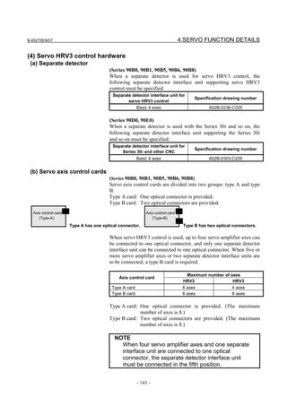
![4.SERVO FUNCTION DETAILS B-65270EN/07
[Number of controlled axes]
When a type A card is used: Up to four servo HRV3 control axes
When a type B card is used: Up to eight servo HRV3 control axes
• When a type A card is used: Up to four axes plus one unit can
be connected.
FSSB-1
AMP AMP AMP AMP Separate
Axis control card (Optical detector
1 2 3 4 interface
(Type-A) cable)
unit 1
(Up to four axes)
• When a type B card is used: Up to eight axes plus two units can
be connected.
FSSB-1
Separate
AMP AMP AMP AMP detector
(Optical 1 2 3 4
cable) interface
unit 1
Axis control card
(Type-B)
FSSB-2
Separate
AMP AMP AMP AMP detector
(Optical 5 6 7 8
cable) interface
unit 2
(Up to eight axes)
• (Reference) When servo HRV3 control is not used: With a type
A card, up to eight axes plus two units can be connected.
FSSB-1
AMP AMP AMP AMP AMP Separate Separate
Axis control card (Optical detector detector
cable) 1 2 3 4 8 interface
(Type-A) interface
unit 1 unit 2
(Series 90D0, 90E0)
There are two types of servo axis cards for Series 90D0 and 90E0:
type A and type B. There is a restriction on axes as follows:
Axis control card Axis control card
(Type-A) (Type-B)
Type A has one optical connector. Type B has two optical connectors.
• Number of units that can be connected to one FSSB optical
connector
Separate detector
Servo HRV3 control is: Amplifier
interface unit
Used. (Note) 10 axes 2 units
Note used. 16 axes 2 units
• Numbers of units that can be connected to the servo cards
Series 90E0 Series 90E0 Series 90D0 Separate
Servo card servo HRV2 servo HRV3 servo HRV2, 3 detector
control control control interface unit
Servo card B13
A02B-0303-H084 Amplifier 12 axes Amplifier 9 axes Amplifier 6 axes 2 units
(Type-A card)
Servo card B26
A02B-0303-H085 Amplifier 24 axes Amplifier 18 axes Amplifier 12 axes 4 units
(Type-B card)
- 142 -](https://image.slidesharecdn.com/b-65270en07-121129013640-phpapp01/85/B-65270-en-07-152-320.jpg)
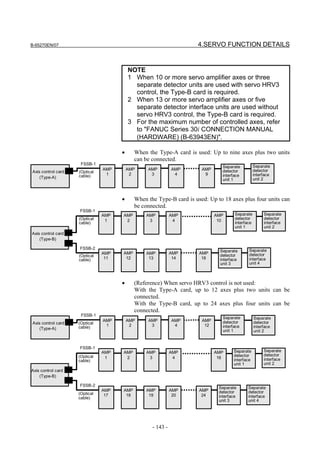
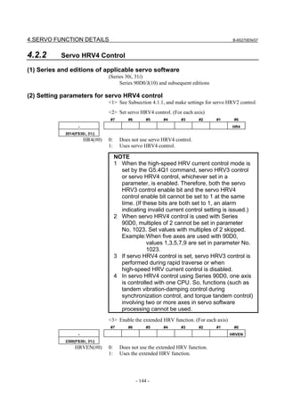
![B-65270EN/07 4.SERVO FUNCTION DETAILS
<4> Set the cutting/rapid velocity loop gain switching function.
#7 #6 #5 #4 #3 #2 #1 #0
- VGCCR
2202(FS30i, 31i)
VGCCR (#1) 0: Does not use the cutting/rapid velocity loop gain switching
function.
1: Uses the cutting/rapid velocity loop gain switching function.
<5> Set the current loop gain magnification.
- Current loop gain magnification in high-speed HRV current control mode
2334(FS30i, 31i)
[Unit of data] %
[Valid data range] 100 to 270
[Recommended value] 150
This parameter is valid only for cutting feed in the high-speed HRV
current control mode.
<6> Set the velocity loop gain magnification.
- Velocity loop gain magnification in high-speed HRV current control mode
2335(FS30i, 31i)
[Unit of data] %
[Valid data range] 100 to 400
This parameter is valid only for cutting feed when the high-speed
HRV current control mode is set.
- Velocity loop gain magnification (cutting/rapid velocity loop gain switching)
2107(FS30i, 31i)
[Unit of data] %
[Valid data range] 100 to 400
This parameter is valid only for cutting feed when the high-speed
HRV current control mode is not set.
<7> This completes parameter setting. To actually enter the
high-speed HRV current control mode, G codes must be
programmed. (See Subsection 4.2.3.)
NOTE
The velocity loop gain is changed as listed below
according to whether the high-speed HRV current
control mode is set or not.
[Series 30i and so on]
High-speed HRV
Feed Velocity loop gain [%]
current control mode
Rapid traverse (1 + No. 2021 / 256) × 100
Set
(G5.4Q1 - G5.4Q0) (1 + No. 2021 / 256) × No. 2335
Cutting feed
(High-speed HRV current control: Velocity loop gain magnification)
Rapid traverse (1 + No. 2021 / 256) × 100
Not set (1 + No. 2021 / 256) × No. 2107
Cutting feed
(Cutting/rapid switching: Velocity loop gain magnification)
- 145 -](https://image.slidesharecdn.com/b-65270en07-121129013640-phpapp01/85/B-65270-en-07-155-320.jpg)
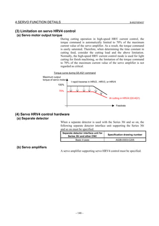
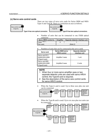
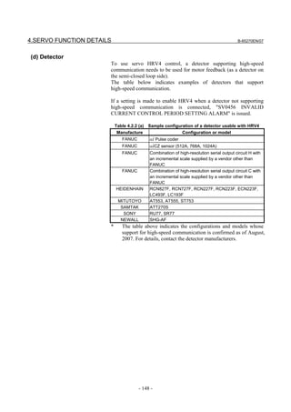
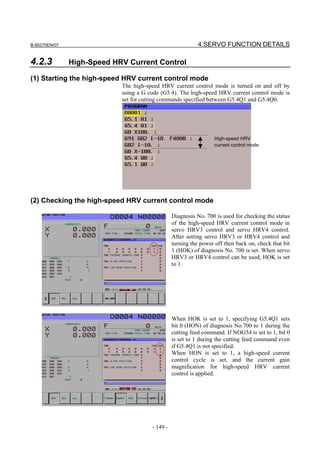
![4.SERVO FUNCTION DETAILS B-65270EN/07
4.3 CUTTING/RAPID SWITCHING FUNCTION
(1) Overview
Increasing the gains of the position loop and velocity loop is effective
in the improvement of cutting profiles. However, the maximum
feedrate and the acceleration of acc./dec. in rapid traverse are
generally higher than those in cutting feed. So, vibration in the
velocity loop or hunting in the position loop may occur in rapid
traverse even when stable cutting feed can be performed with the same
settings. To prevent this problem, the functions below are provided
with a function for switching between parameters for cutting feed and
parameters for rapid traverse.
Velocity feed
Feed forward forward
+ +
Fine acc./dec. Position + Velocity + TCMD filter
gain loop gain
Fig. 4.3 Parameters that can be switched between parameters for cutting feed and for rapid traverse
NOTE
1 The TCMD filter and resonance elimination filter
can be used at the same time by parameter setting.
2 The cutting/rapid switching function is not applied
to the resonance elimination filter.
(2) Setting procedure
(a) Switching of the velocity loop gain and fine acc./dec.
[Series and editions of applicable servo software]
(Series 30i,31i,32i)
Series 90D0/A(01) and subsequent editions
Series 90E0/A(01) and subsequent editions
(Series 15i-B,16i-B,18i-B,21i-B,0i-B,0i Mate-B, Power Mate i)
Series 9096/A(01) and subsequent editions
Series 90B0/A(01) and subsequent editions
Series 90B1/A(01) and subsequent editions
Series 90B6/A(01) and subsequent editions
(Series 0i-C,0i Mate-C,20i-B)
Series 90B5/A(01) and subsequent editions
Series 90B8/A(01) and subsequent editions
- 150 -](https://image.slidesharecdn.com/b-65270en07-121129013640-phpapp01/85/B-65270-en-07-160-320.jpg)
![B-65270EN/07 4.SERVO FUNCTION DETAILS
<1> Cutting/rapid velocity loop gain switching function
When TCMD is saturated during acceleration in rapid traverse,
oscillation is easily generated in the velocity loop at the end of
acceleration in rapid traverse. In some machines, as the feedrate
becomes higher, high-frequency oscillation easily occurs. In such
cases, switching between the gain for cutting feed and the gain
for rapid traverse is effective.
If the cutting/rapid velocity loop gain switching is set, the
conventional velocity gain is used in rapid traverse, and the
overridden value is used during cutting feed. The override value
is usually set to about 150% to 200%. When vibration occurs
only in the stopped state, use the variable proportional gain
function in the stop state. (With Series 90D0, 90E0, 90B0, 90B1,
90B5, 90B6, and 90B8, the variable proportional gain function in
the stop state and the velocity loop high cycle management
function can be used together.)
When servo HRV3 control or HRV4 control is used, a separate
override value can be specified during high-speed HRV current
control. See Section 4.2, "HIGH-SPEED HRV CURRENT
CONTROL".
#7 #6 #5 #4 #3 #2 #1 #0
1742 (FS15i) VGCCR
2202 (FS30i,16i)
0: Disables the cutting/rapid velocity loop gain switching function.
1: Enables the cutting/rapid velocity loop gain switching function.
1700 (FS15i) Velocity loop gain magnification for cutting (%)
2107 (FS30i,16i)
[Valid data range] 100 to 400
[Series30i, 16i, and so on]
Cutting/rapid velocity loop gain
Velocity loop gain [%]
switching function
No. 2202#1=0 (disabled) Always (1 + No. 2021 / 256) × 100
Rapid traverse (1 + No. 2021 / 256) × 100
No. 2202#1=1 (enabled)
Cutting feed (1 + No. 2021 / 256) × No. 2107
[Series15i]
Cutting/rapid velocity loop gain
Velocity loop gain [%]
switching function
No. 1742#1=0 (disabled) Always (1 + No. 1875 / 256) × 100
Rapid traverse (1 + No. 1875 / 256) × 100
No. 1742#1=1 (enabled)
Cutting feed (1 + No. 1875 / 256) × No. 1700
- 151 -](https://image.slidesharecdn.com/b-65270en07-121129013640-phpapp01/85/B-65270-en-07-161-320.jpg)
![4.SERVO FUNCTION DETAILS B-65270EN/07
<2> Cutting/rapid fine acc./dec. switching function (including
feed-forward switching)
Although the optimum time constant of fine acc./dec. during
cutting is about 16 ms, the time constant in rapid traverse should
sometimes be set to 32 to 40 ms to reduce the impact applied at
the time of acc./dec. The feed-forward coefficient that minimizes
cutting profile error and the feed-forward coefficient that
minimizes the time for high-speed positioning in rapid traverse
are not always the same. In such cases, use the cutting/rapid fine
acc./dec. switching function.
NOTE
This function is not supported by the Series 30i
CNC.
#7 #6 #5 #4 #3 #2 #1 #0
1742 (FS15i) FADCH
2202 (FS16i)
0: Disables the cutting/rapid fine acc./dec. switching function.
1: Enables the cutting/rapid fine acc./dec. switching function.
[Series16i, and so on]
Cutting/rapid fine acc./dec. FAD time
Position FF Velocity FF
switching function constant
No. 2202#0=0 (disabled) Always
No. 2109 No. 2092 No. 2069
Rapid traverse
No. 2202#0=1 (enabled)
Cutting feed No. 2143 No. 2144 No. 2145
[Series15i]
Cutting/rapid fine acc./dec. FAD time
Position FF Velocity FF
switching function constant
No. 1742#0=0 (disabled) Always
No. 1702 No. 1985 No. 1962
Rapid traverse
No. 1742#0=1 (enabled)
Cutting feed No. 1766 No. 1767 No. 1768
- 152 -](https://image.slidesharecdn.com/b-65270en07-121129013640-phpapp01/85/B-65270-en-07-162-320.jpg)
![B-65270EN/07 4.SERVO FUNCTION DETAILS
(b) Feed-forward, TCMD filter, 1/2 PI current control switching
[Series and editions of applicable servo software]
(Series 30i,31i,32i)
Series 90D0/A(01) and subsequent editions
Series 90E0/A(01) and subsequent editions
(Series 15i-B,16i-B,18i-B,21i-B,0i-B,0i Mate-B, Power Mate i)
Series 90B0/A(01) and subsequent editions
Series 90B1/A(01) and subsequent editions
Series 90B6/A(01) and subsequent editions
(Series 0i-C,0i Mate-C,20i-B)
Series 90B5/A(01) and subsequent editions
Series 90B8/A(01) and subsequent editions
<1> Cutting/rapid feed-forward switching function
The position feed-forward coefficient and the velocity
feed-forward coefficient can also be changed without using fine
acc./dec. To do this, use the cutting/rapid feed-forward switching
function.
#7 #6 #5 #4 #3 #2 #1 #0
2602 (FS15i) FFCHG
2214 (FS30i,16i)
0: Disables the cutting/rapid feed-forward switching function.
1: Enables the cutting/rapid feed-forward switching function.
[Series30i, 16i, and so on]
Cutting/rapid feed-forward switching function Position FF Velocity FF
No. 2214#4=0 (disabled) Always
No. 2092 No. 2069
Rapid traverse
No. 2214#4=1 (enabled)
Cutting feed No. 2144 No. 2145
[Series15i]
Cutting/rapid feed-forward switching function Position FF Velocity FF
No. 2602#4=0 (disabled) Always
No. 1985 No. 1962
Rapid traverse
No. 2602#4=1 (enabled)
Cutting feed No. 1767 No. 1768
<2> TCMD filter switching
When high frequency vibration occurs only in rapid traverse, use
of the TCMD filter, rather than the resonance elimination filter,
is sometimes effective. On the other hand, in cutting feed,
inserting an unnecessary TCMD filter lowers the vibration limit
of the velocity loop gain because of the delay in the filter. In
such a case, using the TCMD filter only for rapid traverse is
effective.
1895 (FS15i) TCMD filter coefficient
2067 (FS30i,16i)
- 153 -](https://image.slidesharecdn.com/b-65270en07-121129013640-phpapp01/85/B-65270-en-07-163-320.jpg)
![4.SERVO FUNCTION DETAILS B-65270EN/07
1779 (FS15i) TCMD filter coefficient for rapid traverse
2156 (FS30i,16i)
[Series30i, 16i, and so on]
Cutting/rapid feed-forward switching function TCMD filter
No. 2156=0 (disabled) Always No. 2067
Rapid traverse No. 2156
No. 2156≠0 (enabled)
Cutting feed No. 2067
[Series15i]
Cutting/rapid feed-forward switching function TCMD filter
No. 1779=0 (disabled) Always No. 1895
Rapid traverse No. 1779
No. 1779≠0 (enabled)
Cutting feed No. 1895
<3> Switching of the current loop 1/2 PI control function in cutting
feed and rapid traverse
When the cutting/rapid velocity loop gain switching function is
enabled, the current loop 1/2 PI control function is turned off at
the time of rapid traverse. Only when current loop 1/2 PI control
must be used also for rapid traverse while the cutting/rapid
velocity gain switching function is enabled, set the bit for always
enabling the current loop 1/2 PI control function.
#7 #6 #5 #4 #3 #2 #1 #0
1743 (FS15i) CRPI
2203 (FS30i,16i)
0: Disables the current loop 1/2 PI control function.
1: Enables the current loop 1/2 PI control function.
#7 #6 #5 #4 #3 #2 #1 #0
1742 (FS15i) VGCCR
2202 (FS30i,16i)
0: Enables the current loop 1/2 PI control function for both cutting
and rapid traverse.
1: Enables the current loop 1/2 PI control function for cutting only.
NOTE
This function bit has double meanings. One is
above and another is the cutting/rapid velocity loop
gain switching function.
- 154 -](https://image.slidesharecdn.com/b-65270en07-121129013640-phpapp01/85/B-65270-en-07-164-320.jpg)
![B-65270EN/07 4.SERVO FUNCTION DETAILS
#7 #6 #5 #4 #3 #2 #1 #0
1742 (FS15i) PIAL
2202 (FS30i,16i)
1: Always enables the current loop 1/2 PI control function.
[Series30i, 16i, and so on]
No. 2203#2=1 No. 2202#1 No. 2202#2
0 0
Always enables the current loop 1/2 PI control function.
1 1
Enables the current loop 1/2 PI control function for cutting only. 1 0
[Series15i]
No. 1743#2=1 No. 1742#1 No. 1742#2
0 0
Always enables the current loop 1/2 PI control function.
1 1
Enables the current loop 1/2 PI control function for cutting only. 1 0
NOTE
To disable the current loop 1/2 PI control function,
set bit 2 of parameter No. 1743 to 0 (Series 15i) or
bit 2 of parameter No. 2203 to 0 (Series 30i, 16i,
etc.).
- 155 -](https://image.slidesharecdn.com/b-65270en07-121129013640-phpapp01/85/B-65270-en-07-165-320.jpg)
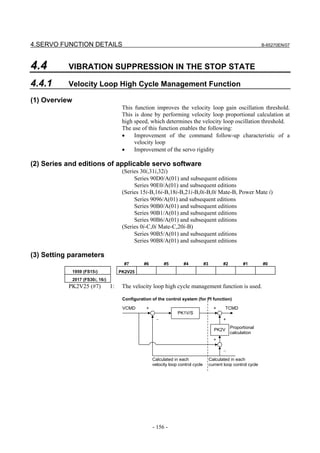
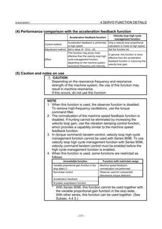
![4.SERVO FUNCTION DETAILS B-65270EN/07
4.4.2 Acceleration Feedback Function
(1) Overview
The acceleration feedback function is used to control velocity loop
oscillation by using motor speed feedback signal multiplied by the
acceleration feedback gain to compensate the torque command.
This function can stabilize unstable servo :
• When motor and machine have a spring coupling.
• When the external inertia is great compared to the motor inertia.
This is effective when vibration is about 50 to 150 Hz.
Fig 4.4.2 is a velocity loop block diagram that includes acceleration
feedback function.
Load inertia
1/(J1 • s)
Torque
Spring
command filter
coupling
VCMD + + +
PK1V/s A/(s + A) Kt 1/(Jm • s)
− − −
Torque Motor inertia
constant
PK2V Ka • s
Speed feedback
PK1V : velocity loop integral gain
PK2V : velocity loop proportional gain
Ka : acceleration feedback gain
Fig. 4.4.2 Velocity loop block diagram that includes acceleration feedback function
(2) Series and editions of applicable servo software
(Series 30i,31i,32i)
Series 90D0/A(01) and subsequent editions
Series 90E0/A(01) and subsequent editions
(Series 15i-B,16i-B,18i-B,21i-B,0i-B,0i Mate-B, Power Mate i)
Series 9096/A(01) and subsequent editions
Series 90B0/A(01) and subsequent editions
Series 90B1/A(01) and subsequent editions
Series 90B6/A(01) and subsequent editions
(Series 0i-C,0i Mate-C,20i-B)
Series 90B5/A(01) and subsequent editions
Series 90B8/A(01) and subsequent editions
(3) Setting parameters
Specifying the following parameters as a negative value enables the
acceleration feedback function.
1894 (FS15i) Acceleration feedback gain
2066 (FS30i, 16i)
[Valid data range] -10 to -20
- 158 -](https://image.slidesharecdn.com/b-65270en07-121129013640-phpapp01/85/B-65270-en-07-168-320.jpg)
![4.SERVO FUNCTION DETAILS B-65270EN/07
4.4.3 Variable Proportional Gain Function in the Stop State
(1) Overview
The velocity gain or load inertia ratio is generally increased if a large
load inertia is applied to a motor, or to improve the response. An
excessively large velocity gain may cause the motor to generate a
high-frequency vibration when it stops. This vibration is caused by
excessive proportional gain of the velocity loop (PK2V) when the
motor is released within the backlash of the machine in the stop state.
This function decreases the velocity loop proportional gain (PK2V) in
the stop state only. The function can suppress the vibration in the stop
state and also enables the setting of a high velocity gain.
(2) Series and editions of applicable servo software
(Series 30i,31i,32i)
Series 90D0/A(01) and subsequent edition
Series 90E0/A(01) and subsequent edition
(Series 15i-B,16i-B,18i-B,21i-B,0i-B,0i Mate-B, Power Mate i)
Series 9096/A(01) and subsequent edition
Series 90B0/A(01) and subsequent edition
Series 90B1/A(01) and subsequent edition
Series 90B6/A(01) and subsequent edition
(Series 0i-C,0i Mate-C,20i-B)
Series 90B5/A(01) and subsequent edition
Series 90B8/A(01) and subsequent edition
(3) Setting parameters
#7 #6 #5 #4 #3 #2 #1 #0
1958 (FS15i) PK2VDN
2016 (FS30i, 16i)
PK2VDN (#3) 1: The variable proportional gain function in the stop state is used.
1730 (FS15i) Variable proportional gain function in the stop state : Stop judgment level
2119 (FS30i, 16i)
[Unit of data] Detection unit
[Recommended value] 2 to 10 (Detection unit: 1 µm)
20 to 100 (Detection unit: 0.1 µm)
With Series 90B0, 90B6, or 90B5, a function for decreasing a set
proportional gain in the stop state to 50% as well as 75%, and a
function for setting an arbitrary magnification only in cutting feed are
available. When decreasing the velocity loop proportional gain in the
stop state to 50%, set the following bit parameter in addition to the
function bit for the function for changing the proportional gain in the
stop state and the parameter for stop determination level.
- 160 -](https://image.slidesharecdn.com/b-65270en07-121129013640-phpapp01/85/B-65270-en-07-170-320.jpg)
![B-65270EN/07 4.SERVO FUNCTION DETAILS
#7 #6 #5 #4 #3 #2 #1 #0
1747 (FS15i) PK2D50
2207 (FS30i, 16i)
PK2D50 (#3) When the variable proportional gain function in the stop state enabled
(K2VDN = 1):
0: The velocity loop proportional gain in the stop state is 75%.
1: The velocity loop proportional gain in the stop state is 50%.
When an arbitrary magnification is used for a proportional gain in the
stop state during cutting feed, set the function bit for stop judgment
level of the function for changing the proportional gain in the stop
state. In addition, set the following parameter:
2737 (FS15i) Variable proportional gain function in the stop state : Arbitrary magnification
in the stop state (during cutting feed only)
2324 (FS30i, 16i)
[Unit of data] %
[Recommended value] 25 to 100
(4) Example of parameter setting
(a) When the cutting feed/rapid traverse switchable velocity loop
gain function (Sec. 4.3) is not used, and
Bit 3 of No. 1958 (Series 15i) or bit 3 of No. 2016 (Series 30i,
16i, and so on) = 1
Actual velocity gain in the stop state=(velocity gain setting)×0.75
(b) When the cutting feed/rapid traverse switchable velocity loop
gain function (Sec. 4.3) is not used,
Bit 3 of No. 1958 (Series 15i) or bit 3 of No. 2016 (Series 30i,
16i, and so on) = 1, and
Bit 3 of No. 1747 (Series 15i) or bit 3 of No. 2207 (Series 30i,
16i, and so on) = 1
Actual velocity gain in the stop state=(velocity gain setting)×0.5
(c) When the cutting feed/rapid traverse switchable velocity loop
gain function (Sec. 4.3) is not used,
Bit 3 of No. 1958 (Series 15i) or bit 3 of No. 2016 (Series 30i,
16i, and so on) = 1, and
No. 2373 (Series 15i) or No. 2324 (Series 30i,16i, and so on) = α
Actual velocity gain in the stop state=(velocity gain setting)×α/100
When the absolute value of an error is lower than the stop judgment
level, the function changes the proportional gain of the velocity loop
(PK2V) to 75% or 50% of the set value.
If the machine vibrates while in the stop state, enable this function and
set a value greater than the absolute value of the error causing the
vibration as the stop judgment level. The function cannot stop the
vibration of a machine in the stop state when the current velocity loop
proportional gain is too high. If this occurs, reduce the velocity loop
proportional gain.
- 161 -](https://image.slidesharecdn.com/b-65270en07-121129013640-phpapp01/85/B-65270-en-07-171-320.jpg)
![4.SERVO FUNCTION DETAILS B-65270EN/07
Error
Velocity loop proportional gain ( PK2V) 100%
Error = + (stop judgement level)
Velocity loop
Error = 0
proportional gain (PK2V) 75% or 50%
Error = − (stop judgement level)
Velocity loop proportional gain ( PK2V) 100%
Fig. 4.4.3 Relationship between error and velocity loop proportional gain
(PK2V)
NOTE
This function is disabled when the velocity loop
high cycle management function (Subsec. 4.4.1) is
used with Series 9096.
[Tip] Example of setting an arbitrary magnification in the stop state
(a) When the cutting feed/rapid traverse switchable velocity loop
gain function (Sec. 4.3) is used, and
Bit 3 of No. 1958 (Series 15i) or bit 3 of No. 2016 (Series 30i,
16i, and so on) = 1
• If the mode in the stop state is the cutting mode:
Actual velocity gain in the stop state = (velocity gain setting
for cutting) × 0.75
• If the mode in the stop state is the rapid traverse mode:
Actual velocity gain in the stop state = (velocity gain setting
for rapid traverse) × 0.75
(b) When the cutting feed/rapid traverse switchable velocity loop
gain function (Sec. 4.3) is used,
Bit 3 of No. 1958 (Series 15i) or bit 3 of No. 2016 (Series 30i,
16i, and so on) = 1, and
Bit 3 of No. 1747 (Series 15i) or bit 3 of No. 2207 (Series 30i,
16i, and so on) = 1
• If the mode in the stop state is the cutting mode:
Actual velocity gain in the stop state = (velocity gain setting
for cutting) × 0.5
• If the mode in the stop state is the rapid traverse mode:
Actual velocity gain in the stop state = (velocity gain setting
for rapid traverse) × 0.5
(c) When the cutting feed/rapid traverse switchable velocity loop
gain function (Sec. 4.3) is used,
Bit 3 of No. 1958 (Series 15i) or bit 3 of No. 2016 (Series 30i,
16i, and so on) = 1, and
No. 2373 (Series 15i) or No. 2324 (Series 30i,16i, and so on) = α
• If the mode in the stop state is the cutting mode:
Actual velocity gain in the stop state = (velocity gain setting
for cutting) × α/100
• If the mode in the stop state is the rapid traverse mode:
Actual velocity gain in the stop state = (velocity gain setting
for rapid traverse) × 0.75
- 162 -](https://image.slidesharecdn.com/b-65270en07-121129013640-phpapp01/85/B-65270-en-07-172-320.jpg)
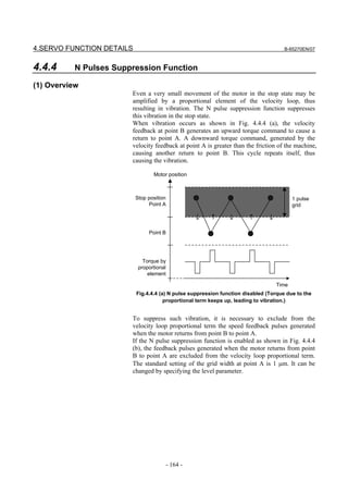
![B-65270EN/07 4.SERVO FUNCTION DETAILS
Motor position
The function works at this point.
N pulse suppression
Stop position level parameter
Point A (setting standard value
is 1 pulse)
Point B
Torque by
proportional
element
Time
Fig. 4.4.4 (b) N pulse suppression function disabled
(The N pulse suppression function restricts the torques due to the proportional term,
thus eliminating vibration.)
(2) Series and editions of applicable servo software
(Series 30i,31i,32i)
Series 90D0/A(01) and subsequent editions
Series 90E0/A(01) and subsequent editions
(Series 15i-B,16i-B,18i-B,21i-B,0i-B,0i Mate-B, Power Mate i)
Series 9096/A(01) and subsequent editions
Series 90B0/A(01) and subsequent editions
Series 90B1/A(01) and subsequent editions
Series 90B6/A(01) and subsequent editions
(Series 0i-C,0i Mate-C,20i-B)
Series 90B5/A(01) and subsequent editions
Series 90B8/A(01) and subsequent editions
(3) Setting parameters
#7 #6 #5 #4 #3 #2 #1 #0
1808 (FS15i) NPSP
2003 (FS30i, 16i)
NPSP (#4) 1: To enable the N pulse suppression function
1992 (FS15i) N-pulse suppression level parameter (ONEPSL)
2099 (FS30i, 16i)
[Valid data range] 0 to 32767
[Standard setting] 400
400 means a single pulse as a detection unit.
- 165 -](https://image.slidesharecdn.com/b-65270en07-121129013640-phpapp01/85/B-65270-en-07-175-320.jpg)
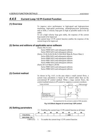
![B-65270EN/07 4.SERVO FUNCTION DETAILS
<2> To enable the function for cutting only, use the following bit in
addition to the previous bit:
#7 #6 #5 #4 #3 #2 #1 #0
1742 (FS15i) VGCCR
2202 (FS30i, 16i)
VGCCR (#1) 1: To enable the current loop 1/2 PI control function for cutting only
(This function is used together with the cutting feed/rapid traverse
velocity loop gain switch function.)
<3> To enable the function at all times while using bit 1 of parameter
No. 1742 (Series 15i) or No. 2202 (Series 16i and so on), use the
following bit in addition to the settings of <1> and <2>:
#7 #6 #5 #4 #3 #2 #1 #0
1742 (FS15i) PIAL
2202 (FS30i, 16i)
PIAL (#2) 1: To enable the current loop 1/2 PI control function at all times
(When this function is used together with the cutting feed/rapid
traverse velocity loop gain switch function)
CAUTION
If the motor activation sound or vibration in the stop
state increases when this parameter is set, turn off
this parameter (do not use this parameter).
(5) Current control PI rate modification
The current control PI rate (p in Fig. 4.5.5) is usually fixed at 1/2, but
can be changed freely.
* This function cannot be used with Series 9096.
2736 (FS15i) Current control PI rate
2323 (FS30i, 16i)
[Valid data range] 0 to 4096
[Unit of data] 4096 represents p = 1.0 (complete PI).
When the value 0 is specified, the specification of 2048 (1/2PI), which
is equivalent to p = 0.5, is assumed.
CAUTION
If you need to increase the velocity gain, in
particular, a value greater than 1/2PI may be set.
However, do not use this parameter usually.
- 167 -](https://image.slidesharecdn.com/b-65270en07-121129013640-phpapp01/85/B-65270-en-07-177-320.jpg)
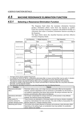
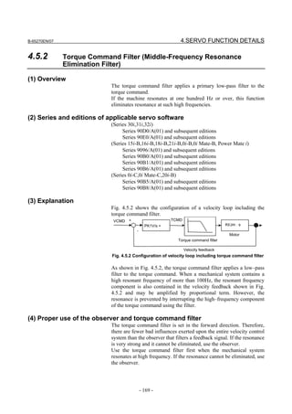
![4.SERVO FUNCTION DETAILS B-65270EN/07
(5) Setting parameters
1895 (FS15i) Torque command filter (FILTER)
2067 (FS30i, 16i)
[Typical setting] 1166 (200 Hz) to 2327 (90 Hz)
When changing the torque command filter setting, see Table 4.5.2.
As the cut-off frequency, select the parameter value corresponding to
a half of the vibration frequency from the table below.
(Example)
In the case of 200-Hz vibration, select a cutoff frequency of 100
Hz for the torque command filter, and set FILTER = 2185.
CAUTION
Do not specify 2400 or a greater value. Such a high
value may increase the vibration.
Table 4.5.2 Parameter setting value of torque command filter
Cutoff Setting value of Cutoff Setting value of
frequency (Hz) parameter frequency (Hz) parameter
60 2810 140 1700
65 2723 150 1596
70 2638 160 1499
75 2557 170 1408
80 2478 180 1322
85 2401 190 1241
90 2327 200 1166
95 2255 220 1028
100 2185 240 907
110 2052 260 800
120 1927 280 705
130 1810 300 622
(6) Cutting feed/rapid traverse switchable torque command filter
With this function, the torque command filter coefficient can be
switched between rapid traverse and cutting feed to improve
contouring accuracy during cutting and increase a maximum feedrate
and maximum acceleration during rapid traverse at the same time.
1779 (FS15i) Torque command filter coefficient for rapid traverse
2156 (FS30i, 16i)
[Valid data range] 1166 (200 Hz) to 2327 (90 Hz)
When 0 is set, the cutting feed/rapid traverse switchable torque
command filter is disabled. The normal filter coefficient (No. 1895 for
Series 15i or No. 2067 for Series 30i, 16i, and so on) is used at all
times.
When a value other than 0 is set, No. 1779 (Series 15i) or No. 2156
(Series 30i, 16i, and so on) is used for stop time, rapid traverse, and
jog feed, and No. 1895 (Series 15i) or No. 2067 (Series 30i, 16i, and
so on) is used for cutting only.
- 170 -](https://image.slidesharecdn.com/b-65270en07-121129013640-phpapp01/85/B-65270-en-07-180-320.jpg)
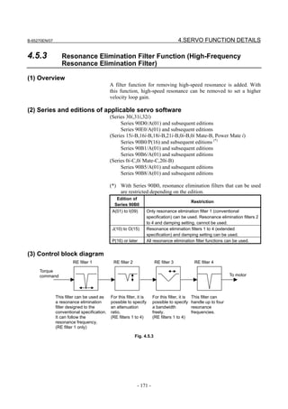
![4.SERVO FUNCTION DETAILS B-65270EN/07
(4) Setting parameters
CAUTION
1 If the frequency of a resonance elimination filter is
set to a low frequency around 100 Hz, the control
system can become unstable, resulting in a large
vibration.
2 Modify parameters in the emergency stop state.
(5) Setting parameters
<1> Setting for resonance elimination filters 2 to 4
The resonance elimination filter has a function for cutting signals of a
particular frequency band. Three parameters are used for this filter.
They specify the center frequency of a range to be cut, a bandwidth to
be cut, and damping separately.
2773 (FS15i) RE filter 2 : Attenuation center frequency
2360 (FS30i, 16i)
[Valid data range] 96 to 1000(HRV1 or HRV2), 96 to 2000(HRV3), 96 to 4000(HRV4)
(independent of the damping setting)
[Unit of data] Hz
2774 (FS15i) RE filter 2 : Attenuation bandwidth
2361 (FS30i, 16i)
[Valid data range] 0 to attenuation center frequency (independent of the damping setting)
[Unit of data] Hz
2775 (FS15i) RE filter 2 : Damping
2362 (FS30i, 16i)
[Valid data range] 0 to 100 (If it is 0, the attenuation ratio is maximized.)
[Unit of data] %
Resonance elimination filters 3 and 4 have the same specification as
resonance elimination filter 2.
2776 (FS15i) RE filter 3 : Attenuation center frequency
2363 (FS30i, 16i)
2777 (FS15i) RE filter 3 : Attenuation bandwidth
2364 (FS30i, 16i)
2778 (FS15i) RE filter 3 : Damping
2365 (FS30i, 16i)
2779 (FS15i) RE filter 4 : Attenuation center frequency
2366 (FS30i, 16i)
2780 (FS15i) RE filter 4 : Attenuation bandwidth
2367 (FS30i, 16i)
2781 (FS15i) RE filter 4 : Damping
2368 (FS30i, 16i)
- 172 -](https://image.slidesharecdn.com/b-65270en07-121129013640-phpapp01/85/B-65270-en-07-182-320.jpg)
![B-65270EN/07 4.SERVO FUNCTION DETAILS
CAUTION
1 For resonance elimination filters 2 to 4, there is no
specification that supports compatibility with
conventional resonance elimination filters. Even if
damping = 0, an arbitrary attenuation bandwidth
can be specified for them.
2 Resonance elimination filters 2 to 4 are enabled if a
nonzero value is set in the attenuation bandwidth
or damping parameters for them. If you do not want
use these resonance elimination filters, reset all the
three parameters (attenuation center frequency,
attenuation bandwidth, and damping) to 0.
3 The parameter for resonance elimination filter 4 is
used to set a coefficient for resonance elimination
filter L when resonance elimination filter L is
enabled (bit 1 of No. 2221=1 (Series 30i, 16i,
etc.)/bit 1 of No. 2609=1 (Series 15i)).
<2> Setting for resonance elimination filter 1
Only resonance elimination filter 1 has the conventional specification
if the damping is 0 and the improved specification if the damping is
not 0.
1706 (FS15i) RE filter 1 : Attenuation center frequency
2113 (FS30i, 16i)
[Valid data range] 250 to 992 (if damping = 0)
96 to 1000(HRV1 or HRV2), 96 to 2000(HRV3), 96 to 4000(HRV4)
(if damping ≠ 0)
[Unit of data] Hz
2620 (FS15i) RE filter 1 : Attenuation bandwidth
2177 (FS30i, 16i)
[Valid data range] 20, 30, 40 (if damping = 0)
0 to attenuation center frequency (if damping ≠ 0)
[Unit of data] Hz
2772 (FS15i) RE filter 1 : Damping
2359 (FS30i, 16i)
[Valid data range] 0 (If it is 0, the resonance elimination filer has the conventional
specification.)
1 to 100 (If it is 1, the attenuation ratio is maximized. For resonance
elimination filer 1.)
[Unit of data] %
- 173 -](https://image.slidesharecdn.com/b-65270en07-121129013640-phpapp01/85/B-65270-en-07-183-320.jpg)
![4.SERVO FUNCTION DETAILS B-65270EN/07
CAUTION
1 If damping = 0 for resonance elimination filter 1,
this filter has the same specification as for
conventional resonance elimination filters. So, its
attenuation bandwidth can be set only to 20, 30, or
40 Hz (specification compatible with conventional
resonance elimination filters).
2 Resonance elimination filter 1 is enabled if a
nonzero value is set in the attenuation bandwidth
or damping parameter for it. If you do not want use
the resonance elimination filter, reset all the three
parameters (attenuation center frequency,
attenuation bandwidth, and damping) to 0.
[Parameters for resonance elimination filters]
For Series 30i or 16i
Attenuation center Attenuation
Damping
frequency [Hz] bandwidth
Resonance elimination filter 2 No.2360 No.2361 No.2362
Resonance elimination filter 3 No.2363 No.2364 No.2365
Resonance elimination filter 4 No.2366 No.2367 No.2368
Resonance elimination filter 1 No.2113 No.2177 No.2359
For Series 15i
Attenuation center Attenuation
Damping
frequency [Hz] bandwidth
Resonance elimination filter 2 No.2773 No.2774 No.2775
Resonance elimination filter 3 No.2776 No.2777 No.2778
Resonance elimination filter 4 No.2779 No.2780 No.2781
Resonance elimination filter 1 No.1706 No.2620 No.2772
- 174 -](https://image.slidesharecdn.com/b-65270en07-121129013640-phpapp01/85/B-65270-en-07-184-320.jpg)
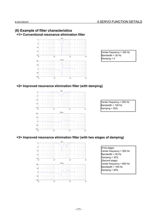
![4.SERVO FUNCTION DETAILS B-65270EN/07
4.5.4 Disturbance Elimination Filter Function (Low-Frequency
Resonance Elimination Filter)
(1) Overview
The disturbance elimination filter function estimates a disturbance by
comparing a specified torque with the actual velocity, and feeds
forward the estimation to the specified torque to suppress the effect of
the disturbance. In particular, this function is useful for a vibration of
50 Hz to 100 Hz.
Disturbance elimination filter Disturbance
+ Motor
Specified + Velocity fb
torque Gain 1/Jm⋅s
Tcmd +
+
Estimated s
disturbance
Gain
Kd Filter Limiter
La
+ Inverse function
gain Filter
- Jmo
Fig. 4.5.4(a) Configuration of disturbance elimination filter
(2) Series and editions of applicable servo software
(Series 30i,31i,32i)
Series 90D0/A(01) and subsequent editions
Series 90E0/A(01) and subsequent editions
(Series 15i-B,16i-B,18i-B,21i-B,0i-B,0i Mate-B, Power Mate i)
Series 90B0/A(01) and subsequent editions
Series 90B1/A(01) and subsequent editions
Series 90B6/A(01) and subsequent editions
(Series 0i-C,0i Mate-C,20i-B)
Series 90B5/A(01) and subsequent editions
Series 90B8/A(01) and subsequent editions
(3) Setting parameters
#7 #6 #5 #4 #3 #2 #1 #0
2611 (FS15i) DISOBS
2223 (FS30i, 16i)
DISOBS (#0) The disturbance elimination filter function is:
0 : Disabled.
1 : Enabled.
2731 (FS15i) Disturbance elimination filter gain (Kd)
2318 (FS30i, 16i)
[Valid data range] 101 to 500
[Typical setting] 500
NOTE
If a gain of 0 to 100 is set, the disturbance
elimination filter function does not operate.
- 176 -](https://image.slidesharecdn.com/b-65270en07-121129013640-phpapp01/85/B-65270-en-07-186-320.jpg)
![B-65270EN/07 4.SERVO FUNCTION DETAILS
2732 (FS15i) Inertia ratio (Rj) (%)
2319 (FS30i, 16i)
[Valid data range] 0 to 32767
[Typical setting] 100
Set an inertia ratio (= machine inertia/motor inertia) in %.
Usually, set 100%.
2733 (FS15i) Inverse function gain (Jmo)
2320 (FS30i, 16i)
[Valid data range] 100 to 2000
[Initial setting] 100 (Increase the setting step by step.)
Set an inverse function gain as a conversion coefficient for
acceleration-to-TCMD conversion. This parameter needs to be
adjusted. As a guideline, set a value not greater than the value
obtained by the following expressions:
Linear motor (The detection unit of the scale is assumed to be p µm.)
Jmo = 466048×p×Jm/Kt/Imax
Rotary motor
Jmo = 1396264×Jm/Kt/Imax
Jm: Weight [kg] or inertia [kgm2]
Kt: Torque constant [N/Ap] or [Nm/Ap]
Imax: Maximum amplifier current [Ap]
NOTE
If an excessively large gain value is set, an
abnormal sound and vibration can occur.
2734 (FS15i) Filter time constant (Tp)
2321 (FS30i, 16i)
• When HRV1, HRV2, or HRV3 is used:
[Valid data range] 0 to 4096
[Typical setting] 3700 (equivalent to T = 10 ms).
* Usually, this value does not need to be changed.
Set a filter time constant for determining an estimated disturbance
velocity by using the following expression:
Tp = 4096 × exp (-t/T)
T: Setting time constant [sec], t = 0.001 [sec]
• When HRV4 is used:
[Valid data range] 0 to 4096
[Typical setting] 3994 (equivalent to T = 10 ms).
* Usually, this value does not need to be changed.
Set a filter time constant for determining an estimated disturbance
velocity by using the following expression:
Tp = 4096 × exp (-t/T)
T: Setting time constant [sec], t = 0.00025 [sec]
- 177 -](https://image.slidesharecdn.com/b-65270en07-121129013640-phpapp01/85/B-65270-en-07-187-320.jpg)
![4.SERVO FUNCTION DETAILS B-65270EN/07
2735 (FS15i) Acceleration feedback limit (La)
2322 (FS30i, 16i)
[Valid data range] 0 to 7282
[Typical setting] 1000
Set a limiter for a feedback torque calculated from acceleration. This
parameter suppresses an excessive motion at the time of adjustment.
The value 7282 represents a maximum amplifier current. When a
160-A amplifier is used, for example, the value 1000 is equivalent to
22 A.
NOTE
In a case where a value close to the torque limit
may be used, the torque is limited if the
acceleration feedback limit is not increased.
(4) Procedure
(1) Make an adjustment according to the procedure below. First,
disable those functions that operate only in the stop state such as
the function for changing the proportional gain in the stop state.
For determining the resonance frequency and adjusting the
disturbance elimination filter, use frequency characteristics
measurement by SERVO GUIDE.
(2) Enable the disturbance elimination filter function, set the
disturbance elimination filter gain to 100 (not functioning), then
measure the frequency characteristics.
With SERVO GUIDE, observe the response waveform obtained
during the above measurement, and set the input amplitude (to
about 500) to allow the waveform to be observed and machine
sound to be heard. A sinusoidal torque command is used, so that
the command does not generate a torque in one direction. The
command is to be executed away from the machine stroke limits.
Swell in gain
Fig. 4.5.4(b) Measurement example using SERVO GUIDE (before
adjustment)
- 178 -](https://image.slidesharecdn.com/b-65270en07-121129013640-phpapp01/85/B-65270-en-07-188-320.jpg)
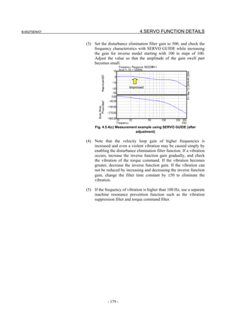
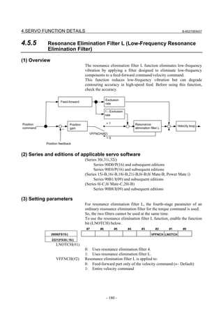
![B-65270EN/07 4.SERVO FUNCTION DETAILS
NOTE
1 To enhance the elimination effect, set VFFNCH to
1.
2 When this parameter is set, the power must be
turned off before operation is continued.
Set the following filter parameters:
2779(FS15i) Resonance elimination filter L/resonance elimination filter 4 attenuation
center frequency
2366(FS30i,16i)
[Valid data range] 5 to 50
[Unit of data] Hz
2780(FS15i) Resonance elimination filter L/resonance elimination filter 4 attenuation
bandwidth
2367(FS30i,16i)
[Valid data range] 3 to 20
[Unit of data] Hz
2781(FS15i) Resonance elimination filter L/resonance elimination filter 4 damping
2368(FS30i,16i)
[Valid data range] 10 to 100 (A maximum attenuation rate is specified when 0 is set.)
[Unit of data] %
CAUTION
To stop the use of this function, be sure to set all
parameters above to 0 then restart the CNC.
NOTE
When the value 4 or a smaller number is specified
as the attenuation center frequency, an illegal
parameter setting alarm (detail number 3663 or
3603) is issued. Set the value 5 or a greater
number.
- 181 -](https://image.slidesharecdn.com/b-65270en07-121129013640-phpapp01/85/B-65270-en-07-191-320.jpg)
![4.SERVO FUNCTION DETAILS B-65270EN/07
2769(FS15i) Resonance elimination filter L/feed-forward filter exclusion rate
2356(FS30i,16i)
[Valid data range] 0 to 100
[Unit of data] %
When resonance elimination filter L is applied to the feed-forward
part, contouring accuracy can degrade. So, this function is used to
balance contouring accuracy and the effect of resonance elimination.
When 100% is set, this filter is not applied to the feed-forward part.
When 50% is set, this filter is applied to a half of the feed-forward
part.
Exclusion rate 100% Exclusion rate 50% Exclusion rate 0%
Contouring accuracy High Contouring accuracy Low
Elimination effect Low Observe contouring accuracy Elimination effect High
and elimination effect
for optimum value adjustment.
Example of effect
Resonance elimination filter L: Disabled Resonance elimination filter L: Enabled
Motor velocity Motor velocity
Motor acceleration Motor acceleration
- 182 -](https://image.slidesharecdn.com/b-65270en07-121129013640-phpapp01/85/B-65270-en-07-192-320.jpg)
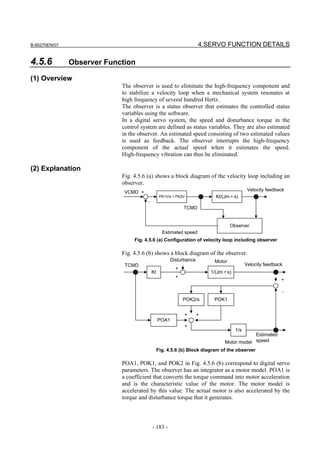
![4.SERVO FUNCTION DETAILS B-65270EN/07
The disturbance torque works on the actual motor. There is a time lag
in the current loop. The POA1 value does not completely coincide
with the actual motor. This is why the motor’s actual velocity differs
from the motor speed estimated by an observer. The observer is
compensated by this difference. The motor model is compensated
proportionally (POK1), and the observer is compensated integrally
(POK2/s).
POK1 and POK2 act as a secondary low–pass filter between the actual
speed and estimated speed. The cutoff frequency and damping are
determined by the POK1 and POK2 values. The difference between
the observer and low-pass filter lies in the existence of a POA1 term.
Using POA1, the observer’s motor model can output an estimated
speed that has a smaller phase delay than the low–pass filter.
When an observer function is validated, the estimated speed in Fig.
4.5.6 (b) is used as velocity feedback to the velocity control loop. A
high–frequency component (100 Hz or more) contained in the actual
motor speed due to the disturbance torque’s influence may be further
amplified by the velocity loop, and make the entire system vibrate at
high frequency. The high frequency contained in the motor’s actual
speed is eliminated by using the velocity feedback that the observer
outputs. High–frequency vibration can be suppressed by feeding back
a low frequency with the phase delay suppressed.
In some systems, the use of the observer function can suppress
vibration during movement but makes the machine unstable while it is
in the stop state. In such cases, use the function for disabling the
observer in the stop state, as explained in Art. (7) of this section.
(3) Series and editions of applicable servo software
(Series 30i,31i,32i)
Series 90D0/A(01) and subsequent editions
Series 90E0/A(01) and subsequent editions
(Series 15i-B,16i-B,18i-B,21i-B,0i-B,0i Mate-B, Power Mate i)
Series 9096/A(01) and subsequent editions
Series 90B0/A(01) and subsequent editions
Series 90B1/A(01) and subsequent editions
Series 90B6/A(01) and subsequent editions
(Series 0i-C,0i Mate-C,20i-B)
Series 90B5/A(01) and subsequent editions
Series 90B5/8(01) and subsequent editions
(4) Setting parameters
#7 #6 #5 #4 #3 #2 #1 #0
1808 (FS15i) OBEN
2003 (FS30i, 16i)
OBEN (#2) 1: To enable the observer function
1859 (FS15i) Observer coefficient (POA1)
2047 (FS30i, 16i)
[Setting value] Keep the standard setting unchanged.
- 184 -](https://image.slidesharecdn.com/b-65270en07-121129013640-phpapp01/85/B-65270-en-07-194-320.jpg)
![B-65270EN/07 4.SERVO FUNCTION DETAILS
1862 (FS15i) Observer coefficient (POK1)
2050 (FS30i, 16i)
• When HRV1, HRV2, or HRV3 is used:
[Setting value] Usually, use the standard setting.
• When HRV4 is used:
[Setting value] 956 → To be changed to 264
1863 (FS15i) Observer coefficient (POK2)
2051 (FS30i, 16i)
• When HRV1, HRV2, or HRV3 is used:
[Setting value] Usually, use the standard setting.
• When HRV4 is used:
[Setting value] 510 → To be changed to 35
(5) Note
The parameter is initially set to such a value (standard setting) that the
cutoff frequency of the filter becomes 30 Hz. With this setting, the
effect of filtering becomes remarkable at resonance frequencies above
the range of 150 Hz to 180 Hz.
To change the cutoff frequency, set parameters POK1 and POK2 to a
value listed below, while paying attention to Table 4.5.6:
Generally, the observer function does not work unless its cutoff
frequency is held below Fd/5 or Fd/6, where Fd is the frequency
component of an external disturbance. However, if this bandwidth is
some 20 Hz or lower, the velocity loop gain also drops or becomes
unstable, possibly causing a fluctuation or wavelike variation.
Table 4.5.6 Changing the observer cutoff frequency
HRV1, HRV2, HRV3 HRV4
Cutoff frequency (Hz)
POK1 POK2 POK1 POK2
10 348 62 90 4
20 666 237 178 16
30 956 510 264 35
40 1220 867 348 62
50 1460 1297 430 96
60 1677 1788 511 136
70 1874 2332 1874 183
(6) Setting observer parameters when the unexpected disturbance torque
detection function is used
The unexpected disturbance torque detection function (see Sec. 4.12)
uses the observer circuit shown in Fig. 4.5.6 (b) to calculate an
estimated disturbance. In this case, to improve the speed of calculation,
change the settings of observer parameters POA1, POK1, and POK2
by following the explanation given in Sec. 4.12.
When the observer function and unexpected disturbance torque
detection function are used together, however, the defaults for POK1
and POK2 must be used.
- 185 -](https://image.slidesharecdn.com/b-65270en07-121129013640-phpapp01/85/B-65270-en-07-195-320.jpg)
![4.SERVO FUNCTION DETAILS B-65270EN/07
(7) Stop time observer disable function
If the observer function is enabled, the machine may fluctuate and
become unstable when it stops. Such a fluctuation or unstable
operation can be prevented by disabling the observer function only in
the stop state.
(8) Setting parameters
<1> Function bit
#7 #6 #5 #4 #3 #2 #1 #0
1960 (FS15i) MOVOBS
2018 (FS30i, 16i)
MOVOBS (#1) The function for disabling the observer in the stop state is:
0: Disabled
1: Enabled ← Set this value.
<2> Level at which the observer is determined as being disabled
1730 (FS15i) Level at which the observer is determined as being disabled
2119 (FS30i, 16i)
[Unit of data] Detection unit
[Typical setting] 1 to 10
If the absolute value of the position error is less than the level at which
the observer is determined as being disabled, the observer function is
disabled.
NOTE
This parameter is also used for the stop
determination level of the function for changing the
proportional gain in the stop state.
(Usage)
Set the function bit and the level at which the observer is determined
as being disabled so that it is greater than the peak absolute value of
the oscillating position error.
- 186 -](https://image.slidesharecdn.com/b-65270en07-121129013640-phpapp01/85/B-65270-en-07-196-320.jpg)
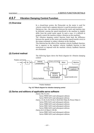
![4.SERVO FUNCTION DETAILS B-65270EN/07
(4) Setting parameters
1718 (FS15i) Number of position feedback pulses for vibration damping control
conversion coefficient
2033 (FS30i, 16i)
[Valid data range] -32767 to 32767
When 0 is set, this function is disabled.
If a negative value is specified, it is internally read as 10 times the
specified value. (-1000=10000)
When a flexible feed gear (F⋅FG) is used
(In the case of using the A/B phase separate type detector and analog SDU)
Set value = Number of feedback pulses per motor revolution, received from a
separate detector/8
(Example 1)
With a 5 mm/rev ball screw, 0.5 µm/pulse separate detector, and
a detection unit of 1 µm, F⋅FG = 1/2
Then,
Set value = 10,000 × 1/8 = 1250
When a flexible feed gear (F⋅FG) is used
(In the case of using the serial separate type detector)
Set value = Number of feedback pulses per motor revolution, received from a
separate detector (after feedback pulse)/8
(Example 2)
If a flexible feed gear is used under the conditions described in
example 1 above,
Set value = 10,000 × 1/2 × 1/8 = 625
When a flexible feed gear (F⋅FG) is used
(In the case of using the analog SDU)
Set value = (Travel distance per motor revolution [mm]) / (detector signal
pitch [mm]) × 512 / 8
(Example 3)
When travel distance per motor revolution=10 [mm], and
detector signal pitch=20 [µm]
Set value = 10 / 0.020 × 512 / 8 = 32000
CAUTION
If the above expression is indivisible, set the
nearest integer.
1719 (FS15i) Vibration-damping control gain
2034 (FS30i, 16i)
[Valid data range] −32767 to 32767
[Standard setting] About 500
This is the feedback gain for vibration damping control.
Adjust the value in increments of about 100, observing the actual
vibration. An excessively large gain will amplify the vibration.
If setting a positive value amplifies the vibration, try setting a negative
value.
- 188 -](https://image.slidesharecdn.com/b-65270en07-121129013640-phpapp01/85/B-65270-en-07-198-320.jpg)
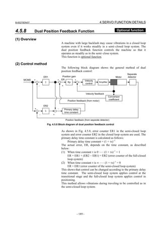
![4.SERVO FUNCTION DETAILS B-65270EN/07
(3) Series and editions of applicable servo software
(Series 30i,31i,32i)
Series 90D0/A(01) and subsequent editions
Series 90E0/A(01) and subsequent editions
(Series 15i-B,16i-B,18i-B,21i-B,Power Mate i)
Series 9096/A(01) and subsequent editions
Series 90B0/A(01) and subsequent editions
Series 90B1/A(01) and subsequent editions
Series 90B6/A(01) and subsequent editions
(Series 0i-C,0i Mate-C,20i-B)
Series 90B5/A(01) and subsequent editions
Series 90B8/A(01) and subsequent editions
(4) Setting parameters
#7 #6 #5 #4 #3 #2 #1 #0
1709 (FS15i) DPFB
2019 (FS30i, 16i)
DPFB (#7) 1: To enable dual position feedback
1861 (FS15i) Dual position feedback maximum amplitude
2049 (FS30i, 16i)
[Setting value] Maximum amplitude (µm)/(minimum detection unit for full-closed
mode × 64)
This parameter should normally be set to 0.
[Unit of data] Minimum detection unit for full-closed mode (µm/p) × 64
If setting = 0, compensation is not clamped. If the parameter is
specified, and a position error larger than the specified value occurs
during semi-closed and full-closed modes, compensation is clamped.
So set the parameter with a value two times the sum of the backlash
and pitch error compensation amounts.
If it is impossible to find the sum, set the parameter to 0.
1971 (FS15i) Dual position feedback conversion coefficient (numerator)
2078 (FS30i, 16i)
1972 (FS15i) Dual position feedback conversion coefficient (denominator)
2079 (FS30i, 16i)
[Setting value] Reduce the following fraction and use the resulting irreducible
fraction.
Number of position feedback pulses
per motor revolution
Conversion Numerator
(Value multiplied by the feed gear)
coefficient ( ) =
Denominator 1 million
With this setting method, however, cancellation in the servo software
internal coefficient may occur depending on constants such as the
machine reduction ratio, causing the motor to vibrate. In such a case,
the setting must be changed.
For details, see Art. (6) in this section.
- 190 -](https://image.slidesharecdn.com/b-65270en07-121129013640-phpapp01/85/B-65270-en-07-200-320.jpg)
![B-65270EN/07 4.SERVO FUNCTION DETAILS
(Example)
When the αi Pulsecoder is used with a tool travel of 10
mm/motor revolution (1 µm/pulse)
Conversion Numerator 10 × 1000 1
coefficient ( ) = =
Denominator 1,000,000 100
1973 (FS15i) Dual position feedback primary delay time constant
2080 (FS30i, 16i)
[Setting value] Set to a value in a range of 10 to 300 msec or so.
[Unit of data] msec
Normally, set a value of around 100 msec as the initial value. If
hunting occurs during acc./dec., increase the value in 50-msec steps. If
a stable status is observed, decrease the value in 20-msec steps. When
0 msec is set, the same axis movement as that in full-closed mode is
performed. When 32767 msec is set, the same axis movement as that
in semi-closed mode is performed.
For a system that requires simultaneous control of two axes, use the
same value for both axes.
1974 (FS15i) Dual position feedback zero-point amplitude
2081 (FS30i, 16i)
[Setting value] Zero width (µm)/minimum detection unit for full-closed mode
[Unit of data] Minimum detection unit (µm/p) for full-closed mode
Positioning is performed so that the difference in the position between
full-closed mode and semi-closed mode does not exceed the pulse
width that corresponds to the parameter-set value.
First set the parameter to 0. If still there is fluctuation, increase the
parameter value.
If this is applied to an axis with a large backlash, a large position error
may remain. For details, see Art. (5) in this section.
1729 (FS15i) Dual position feedback: Level on which the difference in error between the
semi-closed and full-closed modes becomes too large
2118 (FS30i, 16i)
[Setting value] Level on which the difference in error is too large (µm)/minimum
detection unit for full-closed mode
[Unit of data] Minimum detection unit (µm/p) for full-closed mode
If the difference between the Pulsecoder and the separate detector is
greater than or equal to the number of pulses that corresponds to the
value specified by the parameter, an alarm is issued.
Set a value two to three times as large as the backlash.
When 0 is set, detection is disabled.
- 191 -](https://image.slidesharecdn.com/b-65270en07-121129013640-phpapp01/85/B-65270-en-07-201-320.jpg)
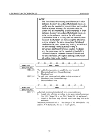
![B-65270EN/07 4.SERVO FUNCTION DETAILS
NOTE
1 If a setting is made to perform the function for monitoring the
difference in error between the semi-closed and full-closed
modes for an axis placed in a simple full-closed loop, the
specification for addition of a backlash compensation and
pitch error compensation is the same as in the case of using
the dual position feedback function. In this case, it is
recommended to make the setting above to "Add a backlash
compensation and pitch error compensation to the closed
loop side and semi-closed loop side at the same time".
2 When the dual check safety function is used with Series 16i,
18i, or 21i, a conversion coefficient for dual position
feedback is used. In this case as well, make the setting
above to "Add a backlash compensation and pitch error
compensation to the closed loop side and semi-closed loop
side at the same time".
(5) Use with smooth backlash compensation
With the Series 30i/31i/32i, a smooth backlash compensation value
can be added onto the semi-closed side by setting the parameter
indicated below to 1 when the dual position feedback function is used
together with smooth backlash compensation.
[Applicable servo software]
(Series 30i,31i,32i)
Series 90D0/Q(17) and subsequent editions
Series 90E0/Q(17) and subsequent editions
[Applicable system software]
- Version 29.0 or later is usable for the following series:
FS30i-A : G002, G012, G022, G032
FS31i-A5 : G121, G131
FS31i-A : G101, G111
FS32i-A : G201
- Version 12.0 or later is usable for the following series:
FS30i-A : G003, G013, G023, G033
FS31i-A5 : G123, G133
FS31i-A : G103, G113
FS32i-A : G203
#7 #6 #5 #4 #3 #2 #1 #0
- SBN
11601(FS30i)
SBN (#6) When both of smooth backlash compensation and dual position
feedback are enabled, a smooth backlash compensation value is:
1: Used for compensation on the semi-closed side.
0: Dependent on the settings of bit 4 of No. 2206 and bit 5 of No.
2010.
- 193 -](https://image.slidesharecdn.com/b-65270en07-121129013640-phpapp01/85/B-65270-en-07-203-320.jpg)
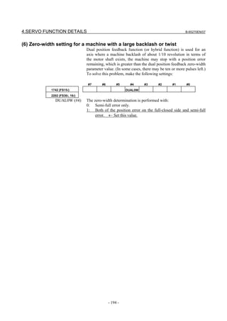
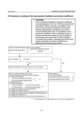
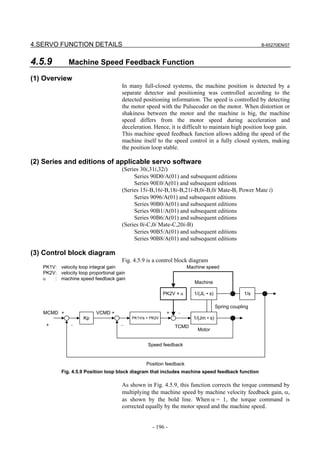
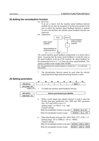

![B-65270EN/07 4.SERVO FUNCTION DETAILS
4.5.10 Machining Point Control
(1) Overview
The machining point control function suppresses vibration after
positioning by attaching an acceleration sensor to the machining point
and using acceleration feedback for control.
NOTE
Machining point control uses an acceleration
sensor. For the setting of an acceleration sensor,
see Subsection 2.1.7.
(2) Series and editions of applicable servo software
(Series 30i,31i,32i)
Series 90D0/P(16) and subsequent editions
Series 90E0/P(16) and subsequent editions
(Series 16i-B,18i-B,21i-B,0i-B,0i Mate-B, Power Mate i)
Series 90B1/I(09) and subsequent editions
(Series 0i-C,0i Mate-C)
Series 90B8/I(09) and subsequent editions
(3) Setting parameters
(a)Setting machining point control
(Function bit setting)
To use machining point control, enable the following function bit:
#7 #6 #5 #4 #3 #2 #1 #0
- MPCEF
2288(FS30i,16i)
MPCEF(#7) Machining point control is:
0: Disabled
1: Enabled
(Band-pass filter setting)
When gain is tuned for machining point control, components other
than a vibration suppression target frequency may cause vibration to
disable a high gain value from being set. To extract a vibration
suppression target frequency component only, be sure to set the
vibration suppression target frequency component in the following
parameter:
- Machining point control/center frequency of band-pass filter
2355(FS30i,16i)
[Unit of data] Hz
[Valid data range] 5 to 200
NOTE
If the value 4 or a smaller number is set, an illegal
parameter setting alarm (detail number 3553 or
3603) is issued. Set the value 5 or a greater number.
- 199 -](https://image.slidesharecdn.com/b-65270en07-121129013640-phpapp01/85/B-65270-en-07-209-320.jpg)
![4.SERVO FUNCTION DETAILS B-65270EN/07
(b)Tuning machining point control
Three parameters are available for tuning machining point control. By
tuning these parameters, vibration after specified
acceleration/deceleration can be suppressed.
• Gain 1
• Timing adjustment parameter
• Gain 2
(Tuning of machining point control gain 1)
Tune machining point control gain 1 so that the acceleration rate
(enclosed by the dashed line in the figure below) after
acceleration/deceleration based on specified acceleration decreases.
Tune machining point control gain 1, starting with a small value
(about 50).
- Machining point control gain 1 (MPCK1)
2266(FS30i,16i)
[Valid data range] 0 to 32767
Machining point control disabled Machining point control enabled (after tuning gain 1)
Acceleration caused by
machine vibration
Acceleration Acceleration
Velocity Velocity
Acceleration caused
by motion command
(Tuning of the timing adjustment parameter)
Tune the machining point control timing adjustment parameter so that
the acceleration rates (enclosed by the dashed lines in the figure
below) after acceleration/deceleration based on specified acceleration
decrease.
This timing adjustment is implemented with a low-pass filter applied
to feedback. Set the parameter so that the cut-off frequency of the
filter is around the frequency of vibration.
After the setting of the timing adjustment parameter is modified, gain
1 needs to be tuned again. To obtain an optimum vibration
suppression effect, tune the timing adjustment parameter and gain 1
repeatedly.
- 200 -](https://image.slidesharecdn.com/b-65270en07-121129013640-phpapp01/85/B-65270-en-07-210-320.jpg)
![B-65270EN/07 4.SERVO FUNCTION DETAILS
Machining point control enabled
(after tuning of gain 1 and the timing adjustment parameter)
Acceleration
Velocity
- Machining point control timing adjustment parameter (MPCTIM)
2096(FS30i,16i)
[Valid data range] 0 to 32767
[Typical setting] The setting of the parameter corresponds to the cut-off frequency of
the low-pass filter.
Set the parameter so that the cut-off frequency is around the frequency
of vibration.
Cut-off Parameter Cut-off Parameter
frequency [Hz] setting frequency [Hz] setting
5 3969 17.5 3669
7.5 3907 20 3612
10 3847 25 3501
12.5 3787 30 3392
15 3728 40 3186
NOTE
When 0 is set in the parameter, the cut-off
frequency of the filter is 40 Hz.
(Tuning of machining point control gain 2)
By tuning machining point control gain 2, vibration may be further
suppressed.
While checking the effect of vibration suppression, tune machining
point control gain 1 and machining point control gain 2 repeatedly.
Tune machining point control gain 2, starting with a small value about
10).
- Machining point control gain 2 (MPCK2)
2265(FS30i,16i)
[Valid data range] 0 to 32767
- 201 -](https://image.slidesharecdn.com/b-65270en07-121129013640-phpapp01/85/B-65270-en-07-211-320.jpg)
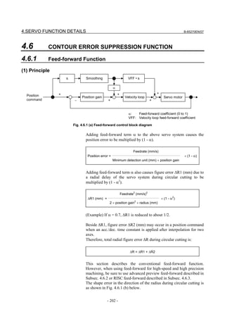
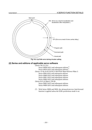
![4.SERVO FUNCTION DETAILS B-65270EN/07
(3) Setting parameters
<1> Enable PI control and the feed-forward function.
#7 #6 #5 #4 #3 #2 #1 #0
1808 (FS15i) PIEN
2003 (FS30i, 16i)
PIEN (#3) 1: To enable PI control
#7 #6 #5 #4 #3 #2 #1 #0
1883 (FS15i) FEED
2005 (FS30i, 16i)
FEED (#1) 1: To enable the feed-forward function
<2> Specify the feed-forward coefficient.
1961 (FS15i) Feed-forward coefficient (FALPH)
2068 (FS30i, 16i)
FALPH = α × 100 or α × 10000
When FALPH is smaller than or equal to 100: In units of 1%
When FALPH is greater than 100: In units of 0.01%
[Typical setting] 70 or 7000
<3> Specify the velocity feed-forward coefficient.
1962 (FS15i) Velocity feed-forward coefficient (VFFLT)
2069 (FS30i, 16i)
VFFLT = 50 (50 to 200)
<4> Run a program to move the axis for cutting feed at maximum
feedrate. Under this condition, check whether the VCMD
waveform observed on the Servo Guide or the servo check board
overshoots and what the shock caused during acceleration
/deceleration is like.
⇒ If an overshoot occurs, or the shock is big, increase the
acc./dec. time constant, or reduce α.
⇒ If an overshoot does not occur, and the shock is small, reduce
the acc./dec. time constant, or increase α.
Linear acc./dec. is more effective than exponential acc./dec.
Using acc./dec. before interpolation can further reduce the figure
error.
- 204 -](https://image.slidesharecdn.com/b-65270en07-121129013640-phpapp01/85/B-65270-en-07-214-320.jpg)
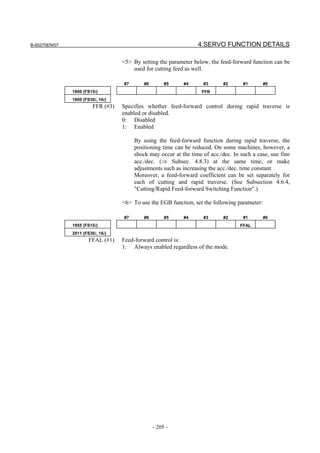

![B-65270EN/07 4.SERVO FUNCTION DETAILS
#7 #6 #5 #4 #3 #2 #1 #0
1883 (FS15i) FEED
2005 (FS30i, 16i)
FEED (#1) 1: The feed-forward function is enabled.
1962 (FS15i) Velocity feed-forward coefficient (VFFLT)
2069 (FS30i, 16i)
[Recommended value] 50 (50 to 200)
<2> Set the coefficient for advanced preview feed-forward control.
1985 (FS15i) Advanced preview feed-forward coefficient (ADFF1)
2092 (FS30i, 16i)
[Recommended value] 9800 to 10000
Advanced preview feed-forward coefficient (0.01% unit)
= α × 10000 (0 ≤ α ≤ 1)
(Example)
When α equals 98.5%, ADFF1 is 9850.
Advanced preview control is configured as shown below:
Deceleration algorithm and function of acc./dec.
before interpolation of CNC
• Acc./dec. method causing no figure errors
Advanced • Deceleration at a point where a large impact
preview would be expected
control Advanced preview feed-forward function of
digital servo
• Improving the tracking ability of the servo
system
Because of this configuration, the function can improve the
feed-forward coefficient up to about 100% without impact and
also reduce figure error.
<3> By specifying the G codes listed below, the modes related to
high-speed and high precision machining such as advanced
preview control can be turned on/off. In each mode, advanced
preview feed-forward is enabled.
NOTE
While the fine acc./dec. (FAD) function is being
used, the advanced preview feed-forward function is
always used, and the advanced preview
feed-forward function cannot be turned on and off
by G codes.
- 207 -](https://image.slidesharecdn.com/b-65270en07-121129013640-phpapp01/85/B-65270-en-07-217-320.jpg)
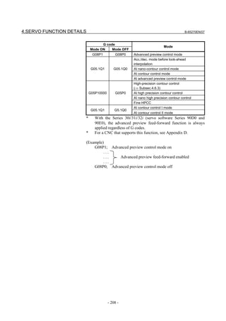
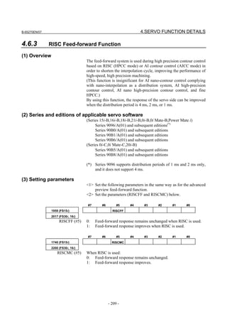
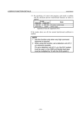
![B-65270EN/07 4.SERVO FUNCTION DETAILS
4.6.4 Cutting/Rapid Feed-forward Switching Function
(1) Overview
To use a separate feed-forward coefficient for each of cutting feed and
rapid traverse, the use of the cutting/rapid fine acc./dec. switching
function has been required conventionally. The cutting feed/rapid
traverse switchable feed-forward function allows a separate coefficient
to be used for each of cutting feed and rapid traverse, without using
the cutting feed/rapid traverse switchable fine acc./dec. function.
(2) Series and editions of applicable servo software
(Series 30i,31i,32i)
Series 90D0/A(01) and subsequent editions
Series 90E0/A(01) and subsequent editions
(Series 15i-B,16i-B,18i-B,21i-B,0i-B,0i Mate-B,Power Mate i)
Series 90B0/A(01) and subsequent editions
Series 90B1/A(01) and subsequent editions
Series 90B6/A(01) and subsequent editions
(Series 0i-C,0i Mate-C,20i-B)
Series 90B5/A(01) and subsequent editions
Series 90B8/A(01) and subsequent editions
(3) Cautions
This function is usable with the modes below. Note that this function
cannot be used with the normal mode.
[Usable modes]
• Advanced preview control mode
• AI contour control mode
• AI nano contour control mode
• High precision contour control mode
• AI high precision contour control mode
• AI nano high precision contour control mode
(*) With the Series 30i/31i/32i, this function can be used regardless
of the specified mode.
(4) Setting parameters
<1> First, set the parameters below in the same way as for the current
feed-forward function.
#7 #6 #5 #4 #3 #2 #1 #0
1808 (FS15i) PIEN
2003 (FS30i, 16i)
PIEN(#3) 1: A switch is made to PI control.
#7 #6 #5 #4 #3 #2 #1 #0
1883 (FS15i) FEED
2005 (FS30i, 16i)
FEED (#1) 1: The feed-forward function is enabled.
- 211 -](https://image.slidesharecdn.com/b-65270en07-121129013640-phpapp01/85/B-65270-en-07-221-320.jpg)
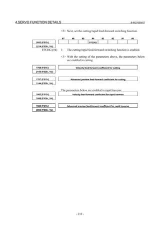
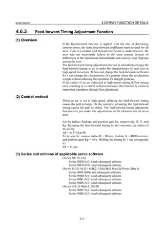
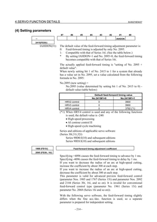
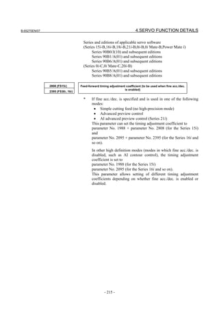
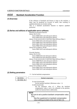
![B-65270EN/07 4.SERVO FUNCTION DETAILS
#7 #6 #5 #4 #3 #2 #1 #0
1884 (FS15i) FCBL
2006 (FS30i, 16i)
FCBL (#0) Backlash compensation is not performed for the position in the
full-closed mode.
0: Invalid
1: Valid
Generally, for a machine in full-closed mode, backlash compensation
is not reflected in positions, so this bit is set. (This parameter is
applicable also to a machine with a semi-closed loop.)
<2> Enable the backlash acceleration function.
#7 #6 #5 #4 #3 #2 #1 #0
1808 (FS15i) BLEN
2003 (FS30i, 16i)
BLEN (#5) 1: To enable backlash acceleration
1860 (FS15i) Backlash acceleration amount
2048 (FS30i, 16i)
[Typical setting] 20 to 600
Offset for the velocity command that is to be added immediately after
a reverse.
1964 (FS15i) Period during which backlash acceleration remains effective
(in units of 2 msec)
2071 (FS30i, 16i)
[Typical setting] 20 to 100
The period during which the acceleration amount is added. At the start
of adjustment, set 20. When a long quadrant protrusion is found,
gradually increase the setting in steps of 10.
<3> When the optimum backlash acceleration amount varies with the
machining feedrate, use the acceleration amount override and the
limit of the acceleration amount.
1725(FS15i) Acceleration amount override
2114(FS30i, 16i)
[Valid data range] 0 to 32767
2751(FS15i) Limit of acceleration amount
2338(FS30i, 16i)
[Valid data range] 0 to 32767 (When 0 is set, the acceleration amount is not limited.)
[Example] Example of setting the acceleration amount when a model such as the
Series 16i is used
Acceleration amount (parameter No. 2048) = 46, acceleration amount
override (parameter No. 2114) = 23, limit of acceleration amount
(parameter No. 2338) = 500
- 217 -](https://image.slidesharecdn.com/b-65270en07-121129013640-phpapp01/85/B-65270-en-07-227-320.jpg)
![4.SERVO FUNCTION DETAILS B-65270EN/07
Backlash acceleration amount
Backlash acceleration amount when override is set
600
500
400
300
200
100
0
0
500
1000
1500
2000
2500
3000
3500
4000
4500
5000
5500
6000
Feedrate (mm/min)
<4> Setting the direction-based backlash acceleration function
When the optimum acceleration amount differs between a reverse
operation in the positive direction and a reverse operation in the
negative direction, set the acceleration amount used for the
reverse operation from the negative direction to positive direction
in the following parameter:
1987(FS15i) Backlash acceleration amount (for reverse from negative to positive
direction)
2094(FS30i, 16i)
[Typical setting] 20 to 600
2753(FS15i) Acceleration amount override (for reverse from negative to positive
direction)
2340(FS30i, 16i)
[Valid data range] 0 to 32767
2754(FS15i) Limit of acceleration amount (for reverse from negative to positive direction)
2341(FS30i, 16i)
[Valid data range] 0 to 32767 (When 0 is set, the acceleration amount is not limited.)
[Parameters used for direction-based setting]
Series30i,16i, and so on
Direction-based Reverse Backlash Acceleration Limit of acceleration
setting direction acceleration amount amount override amount
None Common
No. 2048 No. 2114 No. 2338
From + to -
Present
From - to + No. 2094 No. 2340 No. 2341
Series 15i
Direction-based Reverse Backlash Acceleration Limit of acceleration
setting direction acceleration amount amount override amount
None Common
No. 1860 No. 1725 No .2751
From + to -
Present
From - to + No. 1987 No. 2753 No. 2754
- 218 -](https://image.slidesharecdn.com/b-65270en07-121129013640-phpapp01/85/B-65270-en-07-228-320.jpg)
![B-65270EN/07 4.SERVO FUNCTION DETAILS
<5> If a reverse cut occurs, use the backlash acceleration stop
function.
#7 #6 #5 #4 #3 #2 #1 #0
1953 (FS15i) BLST
2009 (FS30i, 16i)
BLST (#7) 1: To enable the backlash acceleration stop function
NOTE
When the backlash acceleration stop function is
enabled (with BLST = 1), be sure to set a positive
value in the backlash acceleration stop timing
parameter described below. (If 0 or a negative
value is set, backlash acceleration is not
performed.)
1975(FS15i) Backlash acceleration stop distance
2082(FS30i,16i)
[Typical setting] 2 to 5 (detection unit of 1µm), 20 to 50 (detection unit of 0.1µm)
This parameter is related to the distance until backlash acceleration
ends. Determine the parameter value by checking the actual profile.
This completes the general setting procedure for the backlash
acceleration function.
- 219 -](https://image.slidesharecdn.com/b-65270en07-121129013640-phpapp01/85/B-65270-en-07-229-320.jpg)
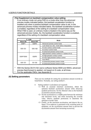
![B-65270EN/07 4.SERVO FUNCTION DETAILS
• Setting method 2 (strict calculation required)
Obtain an optimum backlash acceleration amount for two
different accelerations (an assumed minimum acceleration and an
intermediate acceleration between the minimum and maximum
accelerations), and substitute the obtained value in the following
equation for the backlash acceleration amount override:
Backlash Backlash Acceleration
× Acceleration
acceleration = acceleration × (1+ amount override )
amount amount (setting) 2048
(Feedrate [mm/min])2 128
Acceleration = ×
Radius [mm] Detection unit [µm] × 1000
Find a solution of the simultaneous equations. The results are as
follows:
(Acceleration amount 2) - (Acceleration amount 1)
Acceleration
amount override = (Acceleration (Acceleration ×2048
amount 1) × (Acceleration 2) - amount 2) × (Acceleration 1)
(Acceleration (Acceleration
amount 1) × × (Acceleration 1)
Backlash acceleration amount (Acceleration 2) -
= amount 2)
(setting)
(Acceleration 2) - (Acceleration 1)
Finally, operate at the maximum acceleration, and adjust the limit of
the acceleration amount.
(5) Ignoring the backlash acceleration function at handle feed
To disable the backlash acceleration function at handle feed, set the
following:
#7 #6 #5 #4 #3 #2 #1 #0
1953 (FS15i) BLCU
2009 (FS30i, 16i)
BLCU (#6) 1: To enable the backlash acceleration function during cutting feed
only
NOTE
If bit 3 of parameter No. 1800 is set to 1, the
backlash acceleration function is always enabled,
and it cannot be disabled.
With following series and editions of servo software, the bit shown
below can also be used to enable the backlash acceleration function
only during cutting.
- Series 90B0/C(03) and subsequent editions
- Series 90B5/A(01) and subsequent editions
- Series 90B6/A(01) and subsequent editions
- Series 90B8/A(01) and subsequent editions
- Series 90D0/A(01) and subsequent editions
- Series 90E0/A(01) and subsequent editions
Use of this bit enables and disables the backlash acceleration function
even when bit 3 of parameter No. 1800 is set to 1. Backlash
acceleration is enabled even at the hole bottom during rigid tapping.
- 221 -](https://image.slidesharecdn.com/b-65270en07-121129013640-phpapp01/85/B-65270-en-07-231-320.jpg)
![4.SERVO FUNCTION DETAILS B-65270EN/07
#7 #6 #5 #4 #3 #2 #1 #0
2611 (FS15i) BLCUT2
2223 (FS30i, 16i)
BLCUT2 (#7) 1: To enable the backlash acceleration function during cutting feed
only
[Reference]
Adjustment the backlash acceleration
Run a program for an arc, and make an adjustment while
checking the arc figure on SERVO GUIDE.
(6) Disabling backlash acceleration after a stop
When using the function for disabling backlash acceleration after a
stop, make the setting below. For details, see "(7) Adjustment of
backlash acceleration" in Appendix H.
#7 #6 #5 #4 #3 #2 #1 #0
2696(FS15i) BLSTP2
2283(FS30i,16i)
BLSTP2(#7) 1: Disables backlash acceleration after a stop.
- 222 -](https://image.slidesharecdn.com/b-65270en07-121129013640-phpapp01/85/B-65270-en-07-232-320.jpg)
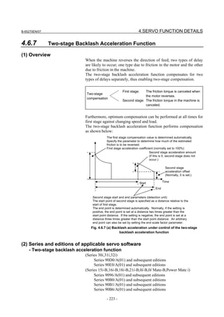
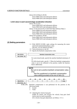
![B-65270EN/07 4.SERVO FUNCTION DETAILS
* By setting a high velocity loop gain, the response of the motor
improves, and quadrant protrusions can be reduced. If the
velocity loop gain is changed in the subsequent adjustments,
the adjustments become complicate. So, increase the velocity
loop gain sufficiently at this stage.
<5> Enable the two-stage backlash acceleration function.
#7 #6 #5 #4 #3 #2 #1 #0
1808 (FS15i) BLEN
2003 (FS30i, 16i)
BLEN (#5) 1: To enable the backlash acceleration function
#7 #6 #5 #4 #3 #2 #1 #0
1957 (FS15i) BLAT
2015 (FS30i, 16i)
BLAT (#6) 1: To enable the two-stage backlash acceleration function
<6> Set the observer-related parameters.
(Related parameters)
1862 (FS15i) Observer gain
2050 (FS30i, 16i)
• When HRV1, HRV2, or HRV3 control is used:
[Setting value] No change is required.
• When HRV4 control is used:
[Setting value] 956 → To be changed to 264
1863 (FS15i) Observer gain
2051 (FS30i, 16i)
• When HRV1, HRV2, or HRV3 control is used:
[Setting value] No change is required.
• When HRV4 control is used:
[Setting value] 510 → To be changed to 35
* When setting an observer gain, follow the settings of other
functions (observer, unexpected disturbance torque detection).
When the two-stage backlash acceleration function is used,
the settings need not be changed.
<7> Adjust observer parameter POA1.
The two-stage backlash acceleration function takes the friction
torque as an estimated disturbance value by using the observer
circuit and determines the first stage acceleration amount.
Therefore, observer parameter POA1 must be adjusted to obtain
correct acceleration. While observing estimated disturbance
value DTRQ, perform acc./dec. to adjust POA1 to the optimum
value.
- 225 -](https://image.slidesharecdn.com/b-65270en07-121129013640-phpapp01/85/B-65270-en-07-235-320.jpg)
![4.SERVO FUNCTION DETAILS B-65270EN/07
The procedure for this adjustment is similar to the
procedure for adjusting observer-related
parameters in the unexpected disturbance torque
detection function (Subsection 4.12.1). Make an
adjustment by following steps <5> and <6> in (3),
"Parameter adjustment methods", in Subsection
4.12.1 in this parameter manual. When the
unexpected disturbance torque detection function
is used, and the adjustment has already been
made, re-adjustment is not needed.
1859 (FS15i) Observer parameter (POA1)
2047 (FS30i, 16i)
[Setting value] Adjusted value (Make an adjustment according to steps <5> and <6>
in (3) in Subsec. 4.12.1.)
1980 (FS15i) Torque offset parameter
2087 (FS30i, 16i)
[Setting value] Adjusted value (If the center of an estimated disturbance value does
not become zero on an axis such as the gravity axis, make an
adjustment according to step <6> in (3) in Subsec. 4.12.1.)
<8> Adjusting the first stage acceleration
Specify the following parameters.
1860 (FS15i) First stage backlash acceleration amount (%)
2048 (FS30i, 16i)
[Unit of data] % (Backlash acceleration amount necessary to reverse the torque that
is equal to the friction torque in amount is assumed to be 100%.)
[Typical setting] 50 (Normally, optimum values range from 20% to 70%.)
To set a backlash acceleration amount of 0, -100 needs to be set.
Acceleration amount when the
direction of feed is reversed
Current friction torque 0
-100%
- 226 -](https://image.slidesharecdn.com/b-65270en07-121129013640-phpapp01/85/B-65270-en-07-236-320.jpg)
![B-65270EN/07 4.SERVO FUNCTION DETAILS
1987 (FS15i) First stage acceleration amount from negative direction to positive direction
2094 (FS30i, 16i) (%)
[Unit of data] %
Normally, this parameter is set to 0. If the quadrant protrusion varies
with the reverse direction of the position command in the machine
conditions, set an appropriate value in this parameter.
When this parameter is set, parameter No. 1860 (Series 15i) or No.
2048 (Series 30i, 16i, and so on) specifies the first stage
positive-to-negative backlash acceleration amount.
(Setting the first stage acceleration in the parameter window)
- 227 -](https://image.slidesharecdn.com/b-65270en07-121129013640-phpapp01/85/B-65270-en-07-237-320.jpg)
![4.SERVO FUNCTION DETAILS B-65270EN/07
Before two-stage backlash acceleration
adjustment
(A delay in reverse motor rotation causes a
protrusion at each area of quadrant switching.)
First, set the value of [Typical setting]. Then, while viewing the
arc figure, adjust the first stage acceleration amount
parameter.(Make an adjustment at a low feedrate of about F500.)
First stage acceleration amount (adequate) First stage acceleration amount (too large)
(Protrusions caused by machine friction remain, (Cuts are caused by excessively high
but these protrusions are corrected later when acceleration at the time of reverse motor
second stage acceleration is adjusted.) rotation.)
Fig. 4.6.7 (b) Two-stage backlash acceleration (first stage acceleration amount adjustment)
1975 (FS15i) Second stage start position (detection unit)
2082 (FS30i, 16i)
[Unit of data] Detection unit
[Typical setting] 10 (For a detection unit of 1 µm)
100 (For a detection unit of 0.1 µm)
NOTE
1 As the second stage start position, the absolute
value of the setting is used.
2 When setting = 0, the specification of 100 is
internally assumed.
- 228 -](https://image.slidesharecdn.com/b-65270en07-121129013640-phpapp01/85/B-65270-en-07-238-320.jpg)
![B-65270EN/07 4.SERVO FUNCTION DETAILS
1982 (FS15i) Second stage end scale factor
2089 (FS30i, 16i)
[Unit of data] In units of 0.1
[Valid data range] Other than Series 9096: 0 to 10279 (multiplication by 0 to 1027.9)
Series 9096: 0 to 642 (multiplication by 0 to 64.2)
[Typical setting] Normally, this value may be set to 0.
When the second stage end scale factor is set to 0, the second stage
acceleration distance is assumed as follows:
If a positive value is set as the second stage start position, a value
obtained by multiplying the start position by 2 is assumed.
If a negative value is set as the second stage start position, a value
obtained by multiplying the start position by 3 is assumed.
By setting the second stage end scale factor, the second stage
acceleration distance may be set to any value.
(Setting example)
When the second stage start position is set to 10, and the second
stage end scale factor is set to 50 (meaning multiplication by 5),
second stage acceleration is performed as shown below.
First stage Second stage acceleration amount
acceleration amount
10 50
Second stage acceleration distance=
Second stage start position × 5
Second stage start position Second stage end position
=Second stage start position
+Second stage acceleration distance
Fig. 4.6.7 (c) Second stage end scale factor
(Second stage acceleration setting in the parameter window)
- 229 -](https://image.slidesharecdn.com/b-65270en07-121129013640-phpapp01/85/B-65270-en-07-239-320.jpg)
![4.SERVO FUNCTION DETAILS B-65270EN/07
Before start/end parameter adjustment
Set the following:
Start/end parameter = Value of [Typical setting]
Second stage acceleration amount = 500
Then, adjust the start/end parameter while viewing the timing of
second stage acceleration from the arc figure.
Start/end parameter (adequate) Start/end parameter (insufficient)
(A larger second stage acceleration amount is set (The time for second stage acceleration is too
to view the timing of second stage acceleration, so short, so that second stage protrusions are not
that cuts occur. This is corrected later.) fully eliminated.)
Fig. 4.6.7 (d) Two-stage backlash acceleration (adjustment of start position and end scale factor)
NOTE
Note that the two-stage backlash acceleration
cannot be used together with the backlash stop
function.
Second stage acceleration is not completed by nature until a distance
specified by "Second stage end scale factor" is moved. For example, if
only several microns are moved after the direction is reversed, second
stage acceleration continues. To prevent such continued acceleration
from occurring, set a maximum allowable duration of time with the
parameter below.
- 230 -](https://image.slidesharecdn.com/b-65270en07-121129013640-phpapp01/85/B-65270-en-07-240-320.jpg)
![B-65270EN/07 4.SERVO FUNCTION DETAILS
1769 (FS15i) Two-stage backlash acceleration end timer
2146 (FS30i, 16i)
[Unit of data] ms
[Typical setting] 50
<9> Second stage acceleration adjustment
The two-stage backlash acceleration function has effect even if
only first stage is used. However, a protrusion may linger
because of machine friction. In such a case second stage is
useful.
Adjust the second stage acceleration so that it falls in a range
where no cut occurs.
1724 (FS15i) Second stage acceleration amount for two-stage backlash acceleration
2039 (FS30i, 16i)
[Typical setting] 100 (Too large a value could cause a cut at low feedrate.)
NOTE
When second stage acceleration is not used, set
second stage acceleration amount = 0. The setting
of second stage start position = 0 alone cannot
disable second stage acceleration.
1790 (FS15i) Second stage offset for two-stage backlash acceleration
2167 (FS30i, 16i)
Normally, set 0.
Offset for the second stage acceleration amount. See Fig. 4.6.7 (a).
The second stage
acceleration amount is
adjusted to eliminate
protrusions and cuts.
Before second stage acceleration Second stage acceleration amount
amount adjustment (too large) (adequate)
Fig. 4.6.7 (e) Two-stage backlash acceleration (second stage acceleration amount adjustment)
- 231 -](https://image.slidesharecdn.com/b-65270en07-121129013640-phpapp01/85/B-65270-en-07-241-320.jpg)
![4.SERVO FUNCTION DETAILS B-65270EN/07
<10>Second stage acceleration override adjustment
Second stage acceleration amounts can be overridden according
to the circular acceleration.
When using the second stage acceleration override function, set the
following.
#7 #6 #5 #4 #3 #2 #1 #0
1960 (FS15i) OVR8
2018 (FS30i, 16i)
OVR8 (#2) 0: The format of the second stage acceleration override is in
reference to 4096.
1: The format of the second stage acceleration override is in
reference to 256.
Normally, set it to 1.
1725 (FS15i) Second stage acceleration override
2114 (FS30i, 16i)
[Valid data range] 0 to 32767
When the second stage acceleration override function is used, the
second stage acceleration amount of two-stage backlash acceleration is
found from the following formula:
(Second stage acceleration amount)=
(Second stage override setting)
(Second stage acceleration amount setting) × 1 + α ×
a
If OVR8 = 1, a = 256
If OVR8 = 0, a = 4096
Here, let α be a circular acceleration, R be a radius (mm), F be a
circular feedrate (mm/min), and P be a detection unit (mm). Then, α
can be expressed as:
2
α = (F / 60 × 0.008)2 / P
R
So, the second stage override setting and acceleration amount are
related as follows:
a (Second stage acceleration amount)
(Second stage override setting) = × − 1
α (Second stage acceleration amount setting)
Example)
When using a second stage acceleration amount override, adjust the
backlash second stage acceleration amount for two types of feedrates.
Suppose that the adjusted values below are obtained.
No. 1960#2 (Series 15i)=1, No. 2018#2 (Series 30i, 16i, and so on)=1
i) In the case of R10, F1000 (detection unit of 1 µm), the optimal
second stage acceleration amount is 40.
ii) In the case of R10, F6000 (detection unit of 1 µm), the optimal
second stage acceleration amount is 100.
From the results above, the expressions below are obtained.
For i)
α=
2
(1000/60 × 0.008)2 0.001 = 3.56
10
- 232 -](https://image.slidesharecdn.com/b-65270en07-121129013640-phpapp01/85/B-65270-en-07-242-320.jpg)
![B-65270EN/07 4.SERVO FUNCTION DETAILS
Expressions <1>
256 40
(Second stage override setting) = × − 1
3.56 (Second stage acceleration amount setting)
For ii)
α=
2
(6000/60 × 0.008)2 0.001 = 128
10
Expressions <2>
256 100
(Second stage override setting) = × − 1
128 (Second stage acceleration amount setting)
From expressions <1> and <2>, the following is obtained:
256 40
× − 1
3.56 (Second stage acceleration amount setting)
256 100
= × − 1
128 (Second stage acceleration amount setting)
Accordingly, (second stage acceleration amount setting) = 38.3 38
From expression <2> (or from expression <1>), (second stage
override setting) = 3.3 3
Set these values in No. 1724 and No. 1725 (Series 15i) or No. 2039
and No. 2114 (Series 30i, 16i, and so on). This completes the setting
of a second stage acceleration override.
NOTE
Second stage override is effective for second stage
offset.
<11>Setting a limit to the second stage acceleration amount
Making an optimum override setting for low-speed and
high-speed ranges may result in an insufficient acceleration
amount in a medium-speed range. To avoid this problem, adjust
overriding for low-speed and medium-speed ranges, and set an
optimum value for the high-speed range in the following
parameter as a limit value.
2751 (FS15i) Limit value for the two-stage backlash second stage acceleration amount
2338 (FS30i, 16i)
[Valid data range] 0 to 32767 (if this parameter is 0, no limit is placed to the second stage
acceleration amount.)
- 233 -](https://image.slidesharecdn.com/b-65270en07-121129013640-phpapp01/85/B-65270-en-07-243-320.jpg)
![4.SERVO FUNCTION DETAILS B-65270EN/07
Second stage Second stage
Second stage
acceleration amount acceleration amount
acceleration amount
Limit value:
No.2338
Gradient:
No.2114
Intercept:
No.2039
Acceleration Acceleration
Measurement Measurement Measurement Measurement Measurement Measurement
point A point B point C point A point B point C
If there is no sufficient acceleration amount at An optimum acceleration amount will be
measurement point B, there remains a quadrant protrusion. obtained at all measurement points.
Fig. 4.6.7 (f) Override adjustment for the second stage acceleration amount of two-stage backlash acceleration
<12>Direction-specific setting for second stage acceleration
If the optimum second stage acceleration amount varies
depending on the direction in which turn-over occurs, specify the
following parameters.
2752 (FS15i) Two-stage backlash second stage acceleration amount override for
turn-over from the negative direction to the positive direction
2339 (FS30i, 16i)
[Recommended value] 100
2753 (FS15i) Second stage acceleration amount override for turn-over from the negative
direction to the positive direction
2340 (FS30i, 16i)
[Valid data range] 0 to 32767
Not used if the two-stage backlash second stage acceleration amount
from the negative direction to the positive direction (parameter No.
2752 (for the Series 15i) and No. 2339 (for the Series 30i, 16i, and so
on)) is 0.
This parameter takes effect when a reverse from the negative direction
to the positive direction takes place if the two-stage backlash second
stage acceleration amount from the negative direction to the positive
direction (parameter No. 2752 (for the Series 15i) and No. 2339 (for
the Series 30i, 16i, and so on)) is not 0.
It is not overridden if the setting is 0.
2754 (FS15i) Second stage acceleration limit value for turn-over from the negative
direction to the positive direction
2341 (FS30i, 16i)
[Valid data range] 0 to 32767
Not used if the two-stage backlash second stage acceleration amount
from the negative direction to the positive direction (parameter No.
2752 (for the Series 15i) and No. 2339 (for the Series 30i, 16i, and so
on)) is 0. This parameter takes effect when a reverse from the negative
direction to the positive direction takes place if the two-stage backlash
second stage acceleration amount from the negative direction to the
positive direction (parameter No. 2752 (for the Series 15i) and No.
2339 (for the Series 30i, 16i, and so on)) is not 0.
If the setting is 0, the second stage acceleration amount is not limited.
- 234 -](https://image.slidesharecdn.com/b-65270en07-121129013640-phpapp01/85/B-65270-en-07-244-320.jpg)
![B-65270EN/07 4.SERVO FUNCTION DETAILS
[Parameters used for direction-based setting]
Series30i,16i, and so on
Direction-based Reverse Second stage Acceleration Acceleration
setting direction acceleration amount override limit value
None Common
No.2039 No.2114 No.2338
From + to -
Present
From - to+ No.2339 No.2340 No.2341
Series 15i
Direction-based Reverse Second stage Acceleration Acceleration
setting direction acceleration amount override limit value
None Common
No.1724 No.1725 No.2751
From + to -
Present
From - to+ No.2752 No.2753 No.2754
(Tip) Supplement on backlash compensation value setting
In an ordinary mode not using FAD (in a mode other than the advanced
preview modes indicated below), the backlash acceleration function is
enabled only when a positive backlash compensation value is set. In the
advanced preview modes indicated below, the backlash acceleration function
is enabled, regardless of the setting of a backlash compensation value.
When FAD is used, an ordinary mode is treated in the same way as the
advanced preview modes. So, the backlash acceleration function is enabled,
regardless of the setting of a backlash compensation value.
G code
Mode
Mode ON Mode OFF
G08P1 G08P0 Advanced preview control mode
Look-ahead acc./dec. mode before interpolation
AI nano contour control mode
G05.1Q1 G05.1Q0
AI contour control mode
AI advanced preview control mode
High-precision contour control (⇒ Subsec.4.6.3)
AI high-precision contour control
G05P10000 G05P0
AI nano high-precision contour control
Fine HPCC
AI advanced preview control I mode
G05.1Q1 G5.1Q0
AI advanced preview control II mode
* With the Series-30i/31i/32i (servo software Series 90D0 and 90E0), advanced
preview feed-forward is applied, not based on G code, at all times.
* For the applicable CNCs, see Appendix D.
- 235 -](https://image.slidesharecdn.com/b-65270en07-121129013640-phpapp01/85/B-65270-en-07-245-320.jpg)
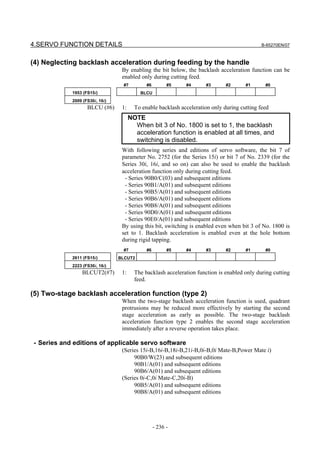
![B-65270EN/07 4.SERVO FUNCTION DETAILS
- Comparison with the conventional second stage acceleration
Start of reverse operation
Conventional second stage
acceleration
First stage acceleration
Second stage acceleration
Second stage start position (set in the detection unit)
Second stage end position (set with a scale factor of start
distance)
The initial value is output until the second stage
Second stage acceleration attenuation start position is reached, and attenuation is
(type 2) performed in the area between the attenuation start
First stage acceleration position and end position.
Second stage acceleration
Second stage attenuation start position (set in the
detection unit)
Second stage end position (set in the detection unit)
Normally, second stage acceleration is not output until the second
stage start distance is reached. The two-stage backlash acceleration
type 2 starts outputting the acceleration amount immediately after the
reverse operation, and starts attenuation after the start distance.
- Setting parameters
#7 #6 #5 #4 #3 #2 #1 #0
2684(FS15i) 2NDTMG
2271(FS30i,16i)
2NDTMG(#5) 0: Does not use the two-stage acceleration type 2.
1: Uses the two-stage acceleration type 2.
1975(FS15i) Second stage attenuation start position
2082(FS30i,16i)
[Valid data range] 0 to 32767
[Unit od data] Detection unit
[Typical setting] 0 to 10 µm
1982(FS15i) Second stage end position
2089(FS30i,16i)
[Valid data range] 0 to 32767
[Unit od data] Detection unit
[Typical setting] 20 to 30 µm
NOTE
For the two-stage backlash acceleration function
type 2, the second stage end position is set directly
in the detection unit.
- 237 -](https://image.slidesharecdn.com/b-65270en07-121129013640-phpapp01/85/B-65270-en-07-247-320.jpg)
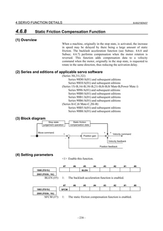
![B-65270EN/07 4.SERVO FUNCTION DETAILS
<2> Set adjustment parameters.
1964 (FS15i) Time during which the static friction compensation function is enabled (in
2-ms units)
2071 (FS30i, 16i)
[Valid data range] 0 to 32767
[Recommended value] 10
1965 (FS15i) Static friction compensation
2072 (FS30i, 16i)
[Valid data range] 0 to 32767
[Recommended value] 100
Offset for the velocity command that is to be added at the start of
travel from a stopped state
1966 (FS15i) Stop state judgement parameter
2073 (FS30i, 16i)
[Valid data range] 1 to 32767
[Method of setting] Stop determination time = (parameter setting) × Ts
Ts=8ms(Series 15i, 16i and so on), 4ms (Series 30i)
If the machine starts moving after stopping for the time set in this
parameter or more, this compensation function is enabled.
NOTE
1 If a small value is set in this parameter, feed at a
low feedrate is regarded by mistake as stop state,
and compensation may not be performed correctly.
In such a case, increase the setting of this
parameter.
2 When the static friction compensation function is
enabled, be sure to set a nonzero positive value in
this parameter.
#7 #6 #5 #4 #3 #2 #1 #0
1953 (FS15i) BLST
2009 (FS30i, 16i)
BLST (#7) 1: The function used to release static friction compensation is
enabled.
1990 (FS15i) Parameter for stopping static friction compensation
2097 (FS30i, 16i)
[Valid data range] 0 to 32767
[Recommended value] 5
Parameter related to the distance the tool travels until the end of the
static friction compensation function. Determine the setting by
looking at the actual shape.
- 239 -](https://image.slidesharecdn.com/b-65270en07-121129013640-phpapp01/85/B-65270-en-07-249-320.jpg)
![4.SERVO FUNCTION DETAILS B-65270EN/07
- Static friction compensation (minus direction)
2347(FS30i)
[Valid data range] 0 to 32767
Speed command offset applied when a movement is started from a
stop in the minus (-) direction.
When No. 2347≠0, direction-by-direction static friction compensation
is enabled. When a movement is made in the minus (-) direction, the
value set in parameter No. 2347 is applied as a static friction
compensation value. When a movement is made in the plus (+)
direction, the value set in parameter No. 2072 is applied.
When No. 2347=0, the value set in parameter No. 2072 is used as a
static friction compensation value.
Applied static friction
compensation
No.2347 Remarks
Movement in Movement in
+ direction − direction
Disables
0 No.2072 No. 2072 direction-by-direction static
friction compensation.
Enables
Non-zero
No.2072 No. 2347 direction-by-direction static
value
friction compensation.
Series and editions of applicable servo software
(Series 30i,31i,32i)
Series 90D0/J(10) and subsequent editions
Series 90E0/J(10) and subsequent editions
- 240 -](https://image.slidesharecdn.com/b-65270en07-121129013640-phpapp01/85/B-65270-en-07-250-320.jpg)
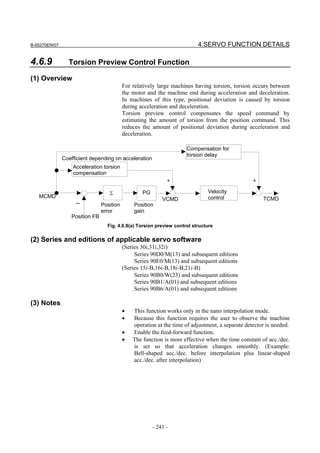
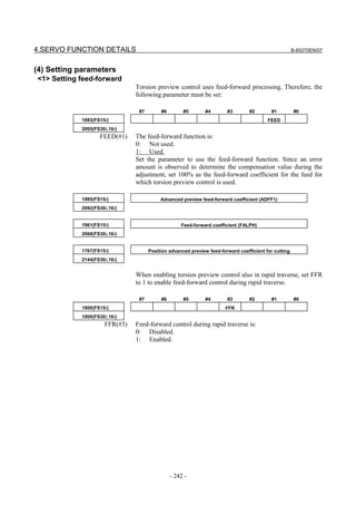
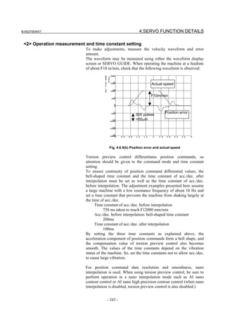
![4.SERVO FUNCTION DETAILS B-65270EN/07
<3> Setting the acceleration
In torsion preview control, three acceleration areas can be specified,
and compensation coefficients can be set separately for these areas.
In a machine having the spring characteristic assumed by torsion
preview control, there are almost proportional relationships between
the acceleration and the torsion amount and position error. Therefore,
setting the acceleration set for the time constant of acc./dec. before
interpolation and one acceleration which is about 1/2 to 3/4 of the
acceleration is normally sufficient.
Compensation
value
Maximum K3
compensation K2
value K1: Compensation value for acceleration 1
K1 K2: Compensation value for acceleration 2
K3: Compensation value for acceleration 3
Acceleration Acceleration Acceleration Acceleration
1 2 3
Fig. 4.6.9(c) Acceleration dependent compensation curve
2796(FS15i) Torsion preview control: acceleration 1 (LSTAC1)
2383(FS30i,16i)
2797(FS15i) Torsion preview control: acceleration 2 (LSTAC2)
2384(FS30i,16i)
2798(FS15i) Torsion preview control: acceleration 3 (LSTAC3)
2385(FS30i,16i)
[Unit of data] D × 1000 [mm/s2] unit (D: detection unit (mm))
[Valid data raneg] 0 to 32767
• If the detection unit is 1 µm, the unit is 1 mm/s2; if the detection
unit is 0.1 µm, the unit is 0.1 mm/s2.
• If the acceleration is set to 0, the setting is ignored.
• Set acceleration values so that acceleration 1 is smaller than
acceleration 2, and acceleration 2 is smaller than acceleration 3.
If acceleration 1 is greater than acceleration 2, the setting of
acceleration 2 is ignored.
In this example, set the acceleration for the time constant of acc./dec.
before interpolation and another lower acceleration.
- LSTAC2
Time constant of acc./dec. before interpolation is 750ms taken to
reach F12000mm/min
→ Acceleration = 12000/60/0.75 = 266.7mm/s2
If the detection unit is 0.1 µm, a value is set in units of 0.1
mm/s2. Therefore,
LSTAC2 = 2667
- 244 -](https://image.slidesharecdn.com/b-65270en07-121129013640-phpapp01/85/B-65270-en-07-254-320.jpg)
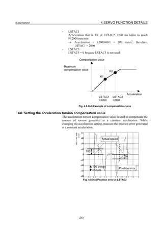
![4.SERVO FUNCTION DETAILS B-65270EN/07
Actual speed
60
45
100 pulses Position
=10µm error
Fig. 4.6.9(f) Position error at LSTAC1
Set the values measured in Fig. 4.6.9 (e) and Fig. 4.6.9 (f) above in the
acceleration torsion compensation values shown below.
(Acceleration torsion amount)
2799(FS15i) Torsion preview control: Acceleration torsion compensation value K1
(LSTK1)
2386(FS30i,16i)
[Unit of data] Detection unit
[Valid data raneg] 0 to 32767
Set the torsion amount generated at acceleration 1 in the detection unit.
When 0 is set, compensation is disabled.
2800(FS15i) Torsion preview control: Acceleration torsion compensation value K2
(LSTK2)
2387(FS30i,16i)
[Unit of data] Detection unit
[Valid data raneg] 0 to 32767
Set the torsion amount generated at acceleration 2 in the detection
unit.
When 0 is set, acceleration 1 and the K1 setting are applied. (See Fig.
4.6.9(g).)
2801(FS15i) Torsion preview control: Acceleration torsion compensation value K3
(LSTK3)
2388(FS30i,16i)
[Unit of data] Detection unit
[Valid data raneg] 0 to 32767
Set the torsion amount generated at acceleration 3 in the detection
unit.
When 0 is set, acceleration 2 and the K2 setting are applied. (See Fig.
4.6.9(h).)
The compensation values are corrected automatically so that the
following is satisfied: K1 ≤ K2 ≤ K3. (See Fig. 4.6.9(i).)
- 246 -](https://image.slidesharecdn.com/b-65270en07-121129013640-phpapp01/85/B-65270-en-07-256-320.jpg)
![B-65270EN/07 4.SERVO FUNCTION DETAILS
Compensation value Compensation value
Maximum compensation Maximum compensation
value value
K3
K2
K1 K1
K2 K3
Acceleration Acceleration
Acceleration 1 Acceleration 2 Acceleration 3 Acceleration 1Acceleration 2 Acceleration 3
Fig. 4.6.9(g) Compensation curve when K2 = 0 Fig. 4.6.9(h) Compensation curve when K3 = 0
Compensation Setting value Compensation Corrected value
value value
K3 K3
K1 K1 K2
K2
Acceleration Acceleration
Acceleration 1 Acceleration 2 Acceleration 3 Acceleration 1 Acceleration 2 Acceleration 3
Fig. 4.6.9(i) Automatic compensation of the compensation curve
(Acceleration torsion amount for each direction)
2804(FS15i) Torsion preview control: Acceleration torsion compensation value K1N (LSTK1N)
2391(FS30i,16i)
[Unit of data] Detection unit
[Valid data raneg] 0 to 32767
Set the amount of torsion generated at acceleration 1 (when the
acceleration is a negative value) in the detection unit.
2805(FS15i) Torsion preview control: Acceleration torsion compensation value K2N (LSTK2N)
2392(FS30i,16i)
[Unit of data] Detection unit
[Valid data raneg] 0 to 32767
Set the amount of torsion generated at acceleration 2 (when the
acceleration is a negative value) in the detection unit.
2806(FS15i) Torsion preview control: Acceleration torsion compensation value K3N (LSTK3N)
2393(FS30i,16i)
[Unit of data] Detection unit
[Valid data raneg] 0 to 32767
Set the amount of torsion generated at acceleration 3 (when the
acceleration is a negative value) in the detection unit. If 4 is set,
acceleration 2 and the settings up to K2 apply.
CAUTION
When all the three accelerations are not used, set 0
in the parameter of the acceleration not used.
- 247 -](https://image.slidesharecdn.com/b-65270en07-121129013640-phpapp01/85/B-65270-en-07-257-320.jpg)
![4.SERVO FUNCTION DETAILS B-65270EN/07
From Fig. 4.6.9 (e) and Fig. 4.6.9 (f), LSTK1 through LSTK3 and
LSTK1N through LSTK3N are set as follows:
LSTK1=60, LSTK2=100, LSTK3=0
LSTK1N=45, LSTK2N=90, LSTK3N=0
<5> Setting the maximum compensation value (enabling torsion preview control)
2795(FS15i) Torsion preview control: Maximum compensation value (LSTCM)
2382(FS30i,16i)
[Unit of data] Detection unit
[Valid data raneg] 0 to 32767
Set the maximum value of the compensation value to be added to the
velocity command in the detection unit. By setting the parameter to a
value greater than 0, torsion preview control is enabled. Set a value
greater than the maximum position error value measured (a value
obtained by multiplication by about 1.2 to 2).
LSTCM=500
The above setting enables this compensation, which reduces the
position error generated at the time of acc./dec.
Actual speed Actual speed
Position error Position error
500 pulses 500 pulses
=50µm =50µm
Fig. 4.6.9(j) Effect of acceleration torsion compensation
<6> Setting the torsion delay compensation value
Just with the acceleration torsion compensation value, the torsion
amount generated at the start of acc./dec. due to delay in velocity
control cannot be corrected, therefore there is a position error still left.
Adjust the torsion delay compensation value while observing the
waveform plotted at the time of acc./dec.
2802(FS15i) Torsion preview control: Torsion delay compensation value KD (LSTKD)
2389(FS30i,16i)
2809(FS15i) Torsion preview control: Torsion delay compensation value KDN (LSTKDN)
2396(FS30i,16i)
LSTKDN is used when there is a difference in delay between the start
of acceleration and the start of deceleration.
- 248 -](https://image.slidesharecdn.com/b-65270en07-121129013640-phpapp01/85/B-65270-en-07-258-320.jpg)
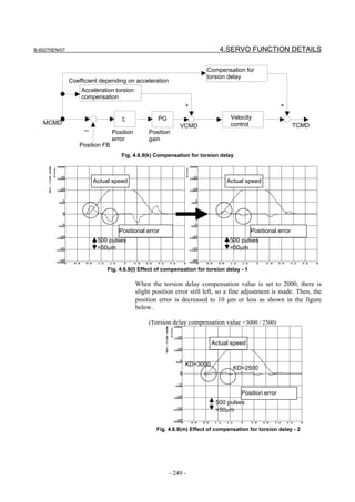
![4.SERVO FUNCTION DETAILS B-65270EN/07
<7> Setting the torsion torque compensation coefficient
Torsion torque compensation is set when an adequate velocity loop
gain cannot be obtained and acceleration torsion compensation does
not work efficiently. The delay in velocity control can be compensated
by adding the differential of the compensation value to TCMD.
2815(FS15i) Torsion preview control: Torsion torque compensation coefficient LSTKT
2402(FS30i,16i)
[Unit of data] %
[Valid data range] 0 to 1000
Compensation coefficient used when the compensation value of
VCMD is differentiated to compensate TCMD. When 100% is set as
the compensation coefficient for TCMD, the acceleration amount of
the motor itself is indicated.
Torsion torque compensation
Coefficient depending on acceleration
Acceleration torsion
Differential LSTKT
compensation
+ +
Σ PG Velocity control
MCMD VCMD TCMD
- Position error Position
gain
Position FB
Fig. 4.6.9(n) Torsion torque compensation
- 250 -](https://image.slidesharecdn.com/b-65270en07-121129013640-phpapp01/85/B-65270-en-07-260-320.jpg)
![B-65270EN/07 4.SERVO FUNCTION DETAILS
4.7 OVERSHOOT COMPENSATION FUNCTION
(1) Setting parameters
#7 #6 #5 #4 #3 #2 #1 #0
1808 (FS15i) OVSC
2003 (FS30i, 16i)
OVSC (#6) 1: To enable the overshoot compensation function
1857 (FS15i) Velocity loop incomplete integral gain (PK3V)
2045 (FS30i, 16i)
[Valid data range] 0 to 32767
[Recommended value] 30000
* Basically, reset the parameter to 0 if you do not use the overshoot
compensation function.
1970 (FS15i) Overshoot compensation counter (OSCTP)
2077 (FS30i, 16i)
[Valid data range] 0 to 32767
[Recommended value] 20
(2) Series and editions of applicable servo software
(Series 30i,31i,32i)
Series 90D0/A(01) and subsequent editions
Series 90E0/A(01) and subsequent editions
(Series 15i-B,16i-B,18i-B,21i-B,0i-B,0i Mate-B,Power Mate i)
Series 9096/A(01) and subsequent editions
Series 90B0/A(01) and subsequent editions
Series 90B1/A(01) and subsequent editions
Series 90B6/A(01) and subsequent editions
(Series 0i-C,0i Mate-C,20i-B)
Series 90B5/A(01) and subsequent editions
Series 90B8/A(01) and subsequent editions
(3) Explanation
(a) Servo system configuration
Fig. 4.7 (a) shows the servo system configuration. Fig. 4.7 (b)
shows the velocity loop configuration.
+
NC Kp Velocity loop 1/s
MCMD − VCMD
Position feedback Kp: Position gain
Fig. 4.7 (a) Digital servo system configuration
+ + TCMD
PK1V/s Kt/ (Jm • s)
VCMD − −
Motor
PK2V
Velocity feedback PK1V: Velocity loop integral gain
PK2V: Velocity loop proportional gain
/s: Integrator
Fig. 4.7 (b) Velocity loop configuration
- 251 -](https://image.slidesharecdn.com/b-65270en07-121129013640-phpapp01/85/B-65270-en-07-261-320.jpg)
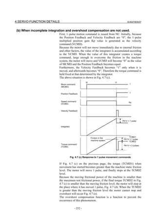
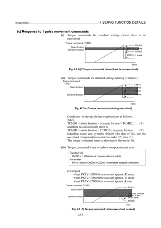
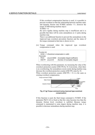
![B-65270EN/07 4.SERVO FUNCTION DETAILS
(4) Improving overshoot compensation for machines using a 0.1-µm
detection unit
(a) Overview
Conventional overshoot compensation performs imperfect integration
only when the error is 0.
A machine using a 0.1-µm detection unit, however, has a very short
period in which the error is 0, resulting in a very short time for
imperfect integration.
The new function judges whether to execute overshoot compensation
when the error is within a predetermined range.
(b) Setting parameters
1994 (FS15i) Overshoot compensation enable level
2101 (FS30i, 16i)
[Valid data range] 0 to 32767
[Unit of data] Detection unit
[Recommended value] 1 (detection unit: 1 µm)
10 (detection unit: 0.1 µm)
To set an error range for which overshoot compensation is enabled, set
∆, as indicated below, as the overshoot compensation enable level.
Error
Imperfect integration disabled
Error = + ∆
Imperfect
Error = 0
integration enabled
Error = − ∆
Imperfect integration disabled
Fig. 4.7 (h) Relationship between error and overshoot compensation
(5) Overshoot compensation type 2
(a) Overview
For a machine using, for example, 0.1-µm detection units, the use of
the conventional overshoot compensation function may generate
minute vibrations when the machine stops, even if the parameter for
the number of incomplete integration is set.
This is caused by the repeated occurrence of the following
phenomena:
• While the machine is in the stopped state, the position error falls
within the compensation valid level, and the integrator is
rewritten. Subsequently, the motor is pushed back by a machine
element such as a machine spring element, causing the position
error to exceed the compensation valid level.
• While the position error is beyond the threshold, a torque
command is output to decrease the position error, then it
decreases to below the threshold again.
In such a case, set the bit indicated below to suppress the minute
vibration.
- 255 -](https://image.slidesharecdn.com/b-65270en07-121129013640-phpapp01/85/B-65270-en-07-265-320.jpg)
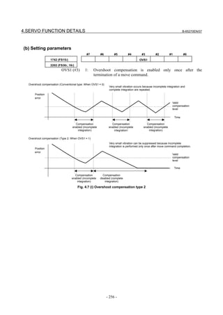
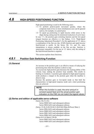
![4.SERVO FUNCTION DETAILS B-65270EN/07
(3) Setting parameters
<1> This parameter specifies whether to enable the position gain
switching function as follows:
#7 #6 #5 #4 #3 #2 #1 #0
1957 (FS15i) PGTW
2015 (FS30i, 16i)
PGTW (#0) The position gain switching function is used.
0: Invalid
1: Valid
<2> This parameter specifies whether to set the velocity at which
position gain switching is to occur, as follows:
1713 (FS15i) Limit speed for enabling position gain switching
2028 (FS30i, 16i)
The position gain is doubled with a speed lower than or equal to the
speed specified above.
[Unit of data] Rotary motor: 0.01 min-1
Linear motor: 0.01 mm/min
[Valid data range] 0 to 32767
[Recommended value] 1500 to 5000
REFERENCE
Using the high-speed positioning velocity increment
system magnification function (→ (5) in Subsec.
4.8.1) can increase the effective velocity to ten
times.
Fig. 4.8.1 (a) shows the relationships between the position error and
velocity command.
(4) When the feed-forward function is used at the same time (position gain
switching function type 2)
When using the position gain switching function together with the
feed-forward function, make the setting below.
(a) Overview
When the conventional position gain switching function is used in
conjunction with the feed-forward function, it can cause an overshoot
at a relative low feed-forward coefficient, sometimes resulting in a
difficulty in adjustment, because also the feed-forward term-based
effect is doubled. Position gain switch function type 2 has been
improved to make position gain switching independently of the
feed-forward function.
- 258 -](https://image.slidesharecdn.com/b-65270en07-121129013640-phpapp01/85/B-65270-en-07-268-320.jpg)
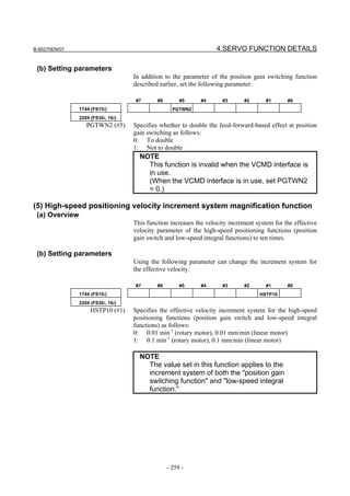
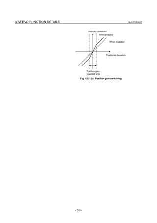
![B-65270EN/07 4.SERVO FUNCTION DETAILS
4.8.2 Low-speed Integral Function
(1) Overview
To ensure that the motor responds quickly, a small time constant must
be set so that a command enabling quick startup is issued.
If the time constant is too small, vibration or hunting occurs because
of the delayed response of the velocity loop integrator, preventing
further reduction of the time constant.
With the low-speed integral function, velocity loop integrator
calculation is performed in low-speed mode only. This function
ensures quick response and high stability while maintaining the
positioning characteristics in the low-speed and stop states.
(2) Series and edition of applicable servo software
(Series 30i,31i,32i)
Series 90D0/A(01) and subsequent editions
Series 90E0/A(01) and subsequent editions
(Series 15i-B,16i-B,18i-B,21i-B,0i-B,0i Mate-B,Power Mate i)
Series 9096/A(01) and subsequent editions
Series 90B0/A(01) and subsequent editions
Series 90B1/A(01) and subsequent editions
Series 90B6/A(01) and subsequent editions
(Series 0i-C,0i Mate-C,20i-B)
Series 90B5/A(01) and subsequent editions
Series 90B8/A(01) and subsequent editions
(3) Setting parameters
<1> Specify whether to enable the low-speed integral function.
#7 #6 #5 #4 #3 #2 #1 #0
1957 (FS15i) SSG1
2015 (FS30i, 16i)
SSG1 The low-speed integral function is used.
0: Invalid
1: Valid
<2> Specify whether to enable integration at acc./dec. time.
1714 (FS15i) Limit speed for disabling low-speed integral at acceleration
2029 (FS30i, 16i)
The integral gain is invalidated during acceleration at a speed higher
than or equal to the specified speed.
[Unit of data] Rotary motor: 0.01 min-1
Linear motor: 0.01 mm/min
[Valid data range] 0 to 32767
[Recommended value] 1000
- 261 -](https://image.slidesharecdn.com/b-65270en07-121129013640-phpapp01/85/B-65270-en-07-271-320.jpg)
![4.SERVO FUNCTION DETAILS B-65270EN/07
1715 (FS15i) Limit speed for enabling low-speed integral at deceleration
2030 (FS30i, 16i)
The integral gain is validated during deceleration at a speed lower
than or equal to the specified speed.
[Unit of data] Rotary motor: 0.01 min-1
Linear motor: 0.01 mm/min
[Valid data range] 0 to 32767
[Recommended value] 1500
REFERENCE
Using the high-speed positioning velocity increment
system magnification function (→ (5) in Subsec.
4.8.1) can increase the effective velocity to ten
times.
This function can specify whether to enable the velocity loop
integration term for two velocity values, the first for acceleration and
the second for deceleration. It works as shown in Fig. 4.8.2 (a).
Valid velocity
at deceleration
Invalid velocity
at acceleration
Time
Integration
disabled
Fig. 4.8.2 (a) Integration invalid range at low-speed integral
- 262 -](https://image.slidesharecdn.com/b-65270en07-121129013640-phpapp01/85/B-65270-en-07-272-320.jpg)
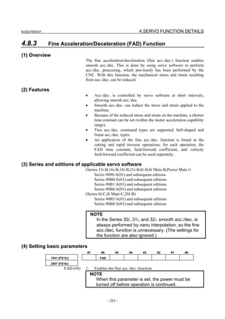
![4.SERVO FUNCTION DETAILS B-65270EN/07
#7 #6 #5 #4 #3 #2 #1 #0
1749 (FS15i) FADL
2209 (FS16i)
FADL (#2) 0: FAD bell-shaped
1: FAD linear type
* Set 1 (linear type) usually .
NOTE
When this parameter is set, the power must be
turned off before operation is continued.
1702 (FS15i) Fine acc./dec. time constant (ms)
2109 (FS16i)
[Valid data range] 8 to 64 (Standard setting: 24)
A value exceeding the valid data range is clamped to the upper or
lower limit of the range.
When the fine acc./dec. and feed-forward functions are used together,
set the coefficient in the following parameter.
(The parameter No. is the same as that used for advanced preview
control.)
1985 (FS15i) Position feed-forward coefficient (in units of 0.01%)
2092 (FS16i)
[Valid data range] 100 to 10000
NOTE
1 Feed-forward control is enabled by setting bit 1 of
No. 1883 (Series 15i) or No. 2005 (Series 16i and
so on) to 1.
2 The velocity feed-forward coefficient is set in
parameter No. 1962 (Series 15i) or No. 2069
(Series 16i and so on) which is the same
parameter as that used for normal operation.
3 Generally, the fine acc./dec. function is enabled in
cutting mode only.
4 If bit 3 of No. 1800 is set to 1, the FAD function is
enabled both for cutting and rapid traverse mode.
(5) Setting parameters for the fine acc./dec. function, used separately for
cutting and rapid traverse
As mentioned above, set the fine acc./dec. function bit and the bit for
selecting the bell-shaped or linear type.
Then, set the following:
#7 #6 #5 #4 #3 #2 #1 #0
1800 (FS15i) FFR
1800 (FS16i)
FFR (#3) 1: Enables feed-forward in rapid traverse also.
- 264 -](https://image.slidesharecdn.com/b-65270en07-121129013640-phpapp01/85/B-65270-en-07-274-320.jpg)
![B-65270EN/07 4.SERVO FUNCTION DETAILS
#7 #6 #5 #4 #3 #2 #1 #0
1742 (FS15i) FADCH
2202 (FS16i)
FADCH (#0) 1: Enables the fine acc./dec. function, used separately for cutting
and rapid traverse.
NOTE
When this parameter is set, the power must be turned off
before operation is continued.
In cutting mode, the following parameters are used:
1766 (FS15i) Fine acc./dec. time constant 2 (ms)
2143 (FS16i)
[Valid data range] 8 to 64
A value that falls outside this range, if specified, is clamped to the
upper or lower limit.
1767 (FS15i) Position feed-forward coefficient for cutting (in units of 0.01%)
2144 (FS16i)
1768 (FS15i) Velocity feed-forward coefficient for cutting (%)
2145 (FS16i)
In rapid traverse mode, the following parameters are used:
1702 (FS15i) Fine acc./dec. time constant (ms)
2109 (FS16i)
[Valid data range] 8 to 64
A value that falls outside this range, if specified, is clamped to the
upper or lower limit.
1985 (FS15i) Position feed-forward coefficient for rapid traverse (in units of 0.01%)
2092 (FS16i)
1962 (FS15i) Velocity feed-forward coefficient for rapid traverse (%)
2069 (FS16i)
NOTE
1 When the settings above are made, both of the fine acc./dec.
time constant and feed-forward coefficient can be automatically
switched for cutting feed or rapid traverse. To switch the
feed-forward coefficient only, use the cutting feed/rapid
traverse switchable feed-forward function. (See Subsec. 4.6.4.)
2 When FAD, used separately for cutting and rapid traverse, is
applied to axes under simple synchronous control, set the
function bit for both the master and slave axes. When the
function is enabled for the master axis only, switching between
cutting and rapid traverse modes cannot be performed.
- 265 -](https://image.slidesharecdn.com/b-65270en07-121129013640-phpapp01/85/B-65270-en-07-275-320.jpg)
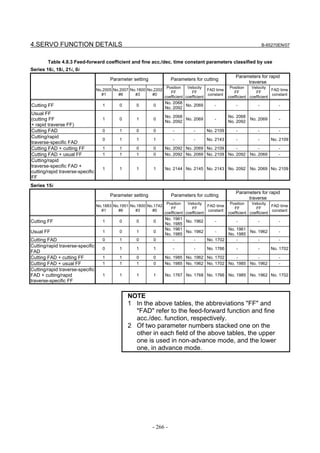
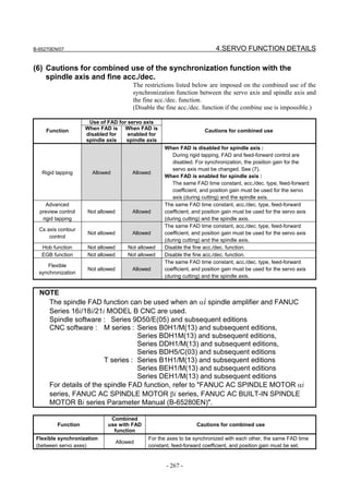
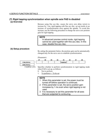
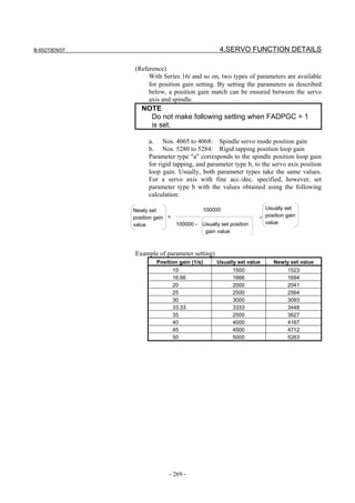
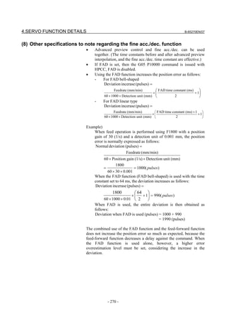
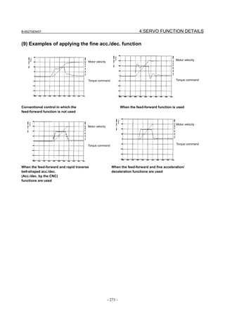
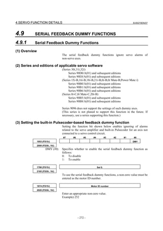
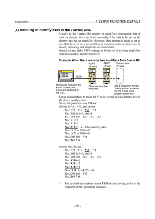
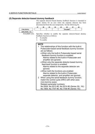
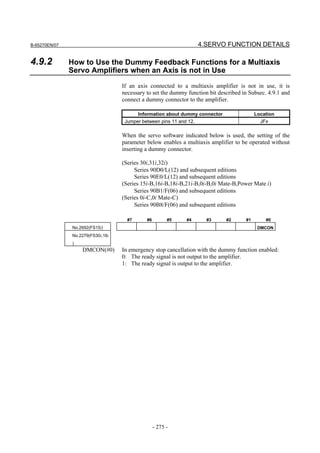
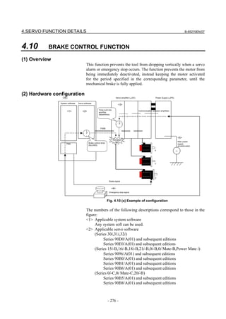
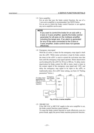
![4.SERVO FUNCTION DETAILS B-65270EN/07
(3) Setting parameters
<1> Brake control function enable/disable bit
#7 #6 #5 #4 #3 #2 #1 #0
1883 (FS15i) BRKC
2005 (FS30i, 16i)
BRKC (#6) 1: The brake control function is enabled.
<2> Activation delay
1976 (FS15i) Brake control timer
2083 (FS30i, 16i)
[Increment system] msec
[Valid data range] 0 to 16000
(Example)
To specify an activation delay of 200 ms, set the brake control
timer usually with 200 (appropriately). Do not set it with 500 or
greater. Also set the timer connected to the emergency stop
contact with the same value as set in the parameter.
<3> Setting the emergency stop timer built into the αiSV
#7 #6 #5 #4 #3 #2 #1 #0
1750 (FS15i) ESPTM1 ESPTM0
2210 (FS30i, 16i)
ESPTM0 (#5), ESPTM1 (#6) Set a period of time from the input of the emergency stop signal into
the αiPS until emergency stop operation is actually performed in the
servo amplifier (αiSV).
ESPTM1 ESPTM0 Delay time
0 0 50 ms (default)
0 1 100ms
1 1 200ms
1 1 400ms
When using brake control, set a time longer than the setting of the
brake control timer (No. 1976 for Series 15i or No. 2083 for Series 16i
and so on).
NOTE
For those axes that are connected to a 2-axis
amplifier or 3-axis amplifier, the parameters above
need to be set in the same way.
(4) Detailed operation
Suppose that there is a machine having horizontal and vertical axes
of motion. When a servo alarm (*) occurs on the horizontal axis but no
error occurs on the vertical axis, the MCCs of the amplifiers for all
axes are turned off. When the emergency stop button is pressed, the
MCCs of the amplifiers for all axes are turned off.
- 278 -](https://image.slidesharecdn.com/b-65270en07-121129013640-phpapp01/85/B-65270-en-07-288-320.jpg)
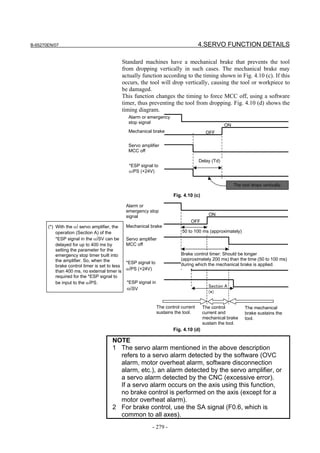
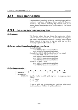
![B-65270EN/07 4.SERVO FUNCTION DETAILS
(Brake control function)
#7 #6 #5 #4 #3 #2 #1 #0
1883 (FS15i) BRKC
2005 (FS30i, 16i)
BRKC (#6) Specifies whether to enable brake control function as follows:
0: To disable
1: To enable
NOTE
When only the brake control function is set, a
gradual stop occurs with the torque limit reduced to
70%.
When the quick stop at emergency stop is enabled,
a gradual stop occurs with the torque limit set to
100%, so that the stop distance is reduced.
1976 (FS15i) Brake control timer
2083 (FS30i, 16i)
[Unit of data] ms
[Setting value] 50 to 100
(4) Timing diagram
Emergency stop signal
Quick stop function
Dynamic brake
Deceleration
by quick stop Deceleration by
function dynamic brake
Motor speed
Fig. 4.11.1 (a) Timing diagram of quick stop function
(5) Connection of amplifier
PSM SPM SVM
Emergency stop contact
(No timer is necessary.)
CX4
2
ESP : :
3 : :
+24 V : :
CX3
1
∼
Coil 3
MCC
Fig. 4.11.1 (b) αi series amplifier
- 281 -](https://image.slidesharecdn.com/b-65270en07-121129013640-phpapp01/85/B-65270-en-07-291-320.jpg)
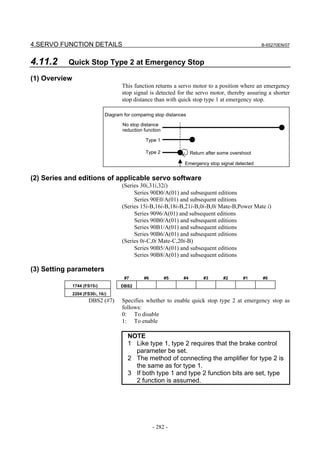
![B-65270EN/07 4.SERVO FUNCTION DETAILS
4.11.3 Lifting Function Against Gravity at Emergency Stop
4.11.3.1 Lifting function against gravity at emergency stop
(1) Overview
This function is intended to lift and stop the vertical axis (Z-axis) of a
vertical machining center when the machine comes to an emergency
stop or power failure.
(2) Series and editions of applicable servo software
(Series 30i,31i,32i)
Series 90D0/A(01) and subsequent editions
Series 90E0/A(01) and subsequent editions
(Series 15i-B,16i-B,18i-B,21i-B,0i-B,0i Mate-B,Power Mate i)
Series 90B0/P(16) and subsequent editions
Series 90B1/A(01) and subsequent editions
Series 90B6/A(01) and subsequent editions
(Series 0i-C,0i Mate-C,20i-B)
Series 90B5/A(01) and subsequent editions
Series 90B8/A(01) and subsequent editions
(3) Setting parameters
Because this function uses quick stop at emergency stop type 2, the
following function bit must be set to 1 (enable). (Quick stop type 1 at
emergency stop (bit 0 of No. 1959 (Series 15i, etc.) or bit 0 of No.
2017 (Series 30i, 16i, etc.) is not needed.)
#7 #6 #5 #4 #3 #2 #1 #0
1744 (FS15i) DBS2
2204 (FS30i, 16i)
DBS2 (#7) Specifies whether to enable quick stop type 2 at emergency stop as
follows:
0: To disable
1: To enable
2786 (FS15i) Distance to lift
2373 (FS30i, 16i)
This parameter is for determining a distance to lift at an emergency
stop. The larger the value, the larger becomes the distance to lift.
[Unit of data] Detection unit or 1µm (→See Subsec.4.11.3.3.)
[Valid data range] -32767 to 32767
[Recommended value] Detection unit 1µm : Approximately 500
Detection unit 0.1µm : Approximately 5000
- 283 -](https://image.slidesharecdn.com/b-65270en07-121129013640-phpapp01/85/B-65270-en-07-293-320.jpg)
![4.SERVO FUNCTION DETAILS B-65270EN/07
NOTE
1 If the brake is in use, it starts working while the
vertical axis is being lifted. So the distance through
which the axis is actually lifted differs from the setting.
2 Whether the parameter values is positive or negative
matches whether the machine coordinate value is
positive or negative.
3 Using this function causes the load to stop after
moving it to one side of the machine. So, it should be
used for the vertical axis (Z-axis) of a vertical
machining center in which an axis retracts in a fixed
single direction at an emergency stop.
2787 (FS15i) Lifting time
2374 (FS30i, 16i)
This parameter determines the lifting time as measured from the time
of an emergency stop. The distortion easing function is executed after
the lifting time has elapsed. This function is intended to decrease the
amount of machine elastic strain that can increase when a vertical axis
is lifted when the machine is about to apply the brake. Executing this
function can reduce the shock that may occur when the axis drops
because the servo amplifier stops energizing. The initial value of the
function is a quarter of the distance to lift.
(See the following figure.)
[Unit of data] ms
[Valid data range] 8 to 32767
[Recommended value] Approximately 16 or 24 ms
NOTE
1 Specify an integer multiple of 8 as the lifting time
2 To use the lifting function against gravity at
emergency stop, specify 8 ms or longer as the lifting
time.
3 If the distortion easing function is not used, specify
the time longer than or equal to the one set in the
brake control timer as the lifting time.
• Velocity command
Vertical axis lifting
Distortion
easing
function
Lifting time
Fig. 4.11.3 (a) Velocity command
- 284 -](https://image.slidesharecdn.com/b-65270en07-121129013640-phpapp01/85/B-65270-en-07-294-320.jpg)
![B-65270EN/07 4.SERVO FUNCTION DETAILS
• Motor position waveform
Time specified in the brake control timer
Distortion easing function: Decreases
the machine elastic strain that increases
The vertical axis is lifted. when the vertical axis is lifted.
The distortion easing function
decreases the shock that may occur
when the servo motor is de-energized.
Emergency stop input Energizing by the amplifier is turned off.
Fig. 4.11.3 (b) Motor position waveform
Using this function requires specifying the following brake control
parameters.
Brake control function bit
#7 #6 #5 #4 #3 #2 #1 #0
1883 (FS15i) BRKC
2005 (FS30i, 16i)
BRKC(#6) The brake control function is:
0 : Disabled.
1 : Enabled ← Use this setting.
Energizing delay time
1976 (FS15i) Brake control timer
2083 (FS30i, 16i)
[Unit of data] ms
[Recommended value] 50 to 100 ms
NOTE
If the vertical axis (Z-axis) is connected to a
multiaxis amplifier, it is necessary to enable the
brake control function for all the axes connected to
the multiaxis amplifier.
Set the time from the instant when an emergency stop signal is input
to αiPS to the instant when the emergency stop function works in the
servo amplifier.
#7 #6 #5 #4 #3 #2 #1 #0
1750 (FS15i) ESPTM1 ESPTM0
2210 (FS30i, 16i)
ESPTM1 ESPTM0 Delay time
0 0 50ms (default value)
0 1 100ms
1 0 200ms
1 1 400ms
- 285 -](https://image.slidesharecdn.com/b-65270en07-121129013640-phpapp01/85/B-65270-en-07-295-320.jpg)
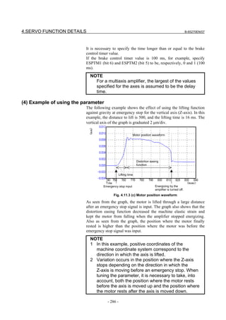
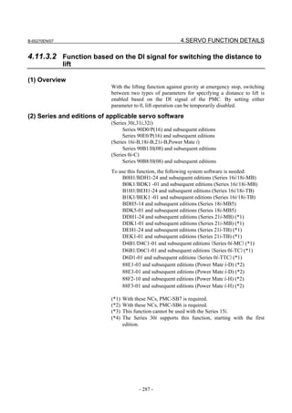
![4.SERVO FUNCTION DETAILS B-65270EN/07
(3) Switching signal
Signal for switching the distance to lift for the lifting function against gravity at
emergency stop
#7 #6 #5 #4 #3 #2 #1 #0
Gn323 SWDBS8 SWDBS7 SWDBS6 SWDBS5 SWDBS4 SWDBS3 SWDBS2 SWDBS1
[Classification] Input signal
[Function] This signal is used to switch the distance to lift when the lifting
function against gravity at emergency stop is enabled. A number
suffixed at the end of the signal represents the number of each
controlled axis.
(Details of operation)
• When this signal (SWDBSx) is set to 0, the distance to lift for the
lifting function against gravity at emergency stop follows the
value set in No. 2373.
• When this signal (SWDBSx) is set to 1, the distance to lift for the
lifting function against gravity at emergency stop follows the
value set in No. 2173.
• The distance to lift depends on the state of this signal (SWDBSx)
present when the emergency stop command is input. (If this
signal is changed during lift operation after the emergency stop
command is input, the change does not become effective until the
lift operation is completed and the excitation is turned off.)
• Among the parameters related to the lifting function against
gravity at emergency stop, the parameters other than those
related to the distance to lift are common, regardless of the state
of this signal (SWDBSx).
(4) Setting parameters
Set the parameters below in addition to the parameters for the lifting
function against gravity at emergency stop.
- Distance to lift (when SWDBSx=0)
2373(FS30i,16i)
This parameter is for determining a distance to lift at an emergency
stop. The larger the value, the larger becomes the distance to lift.
[Unit of data] Detection unit or 1µm (→See Subsec.4.11.3.3.)
[Valid data range] -32767 to 32767
[Recommended value] Detection unit 1µm : Approximately 500 or -500
Detection unit 0.1µm : Approximately 5000 or -5000
This parameter is effective only when the signal (SWDBSx) for
switching the distance to lift for the lifting function against gravity at
emergency stop is set to 0.
To disable lift operation when (SWDBSx) = 0, set 0 in this parameter.
- 288 -](https://image.slidesharecdn.com/b-65270en07-121129013640-phpapp01/85/B-65270-en-07-298-320.jpg)
![B-65270EN/07 4.SERVO FUNCTION DETAILS
- Distance to lift (when SWDBSx=1)
2173(FS30i,16i)
This parameter is for determining a distance to lift at an emergency
stop. The larger the value, the larger becomes the distance to lift.
[Unit of data] Detection unit or 1µm (→See Subsec.4.11.3.3.)
[Valid data range] -32767 to 32767
[Recommended value] Detection unit 1µm : Approximately 500 or -500
Detection unit 0.1µm : Approximately 5000 or -5000
This parameter is effective only when the signal (SWDBSx) for
switching the distance to lift for the lifting function against gravity at
emergency stop is set to 1.
NOTE
1 When a brake is used, brake application starts
during lift operation, so that the set value does not
match the actual lift distance.
2 The parameter polarity matches the polarity of the
machine coordinate system.
3 Use this function only when lift operation does not
cause a mechanical interference.
- 289 -](https://image.slidesharecdn.com/b-65270en07-121129013640-phpapp01/85/B-65270-en-07-299-320.jpg)
![4.SERVO FUNCTION DETAILS B-65270EN/07
4.11.3.3 Method of setting a distance to lift in µm
(1) Overview
When the servo software below is used with the lifting function
against gravity at emergency stop, the parameter for specifying a
distance to lift can be set in [µm], independently of the detection unit.
With this function, a large distance to lift can be used when a small
detection unit is used.
(2) Series and editions of applicable servo software
(Series 30i,31i,32i)
Series 90D0/P(16) and subsequent editions
Series 90E0/P(16) and subsequent editions
(3) Setting parameters
#7 #6 #5 #4 #3 #2 #1 #0
- DUNIT
2298(FS30i)
DUNIT(#7) When the lifting function against gravity at emergency stop is used,
the function that enables the parameter for specifying a distance to lift
to be set in µm, independently of the detection unit, is
0: Not used
1: Used
• When this function is enabled, the parameter (No. 2373 or No.
2173) for specifying a distance to lift for the lifting function
against gravity at emergency stop can be set in µm,
independently of the detection unit.
• When this parameter has been set, the power must be turned off
before operation is continued.
• If this function is used with a CNC that does not support the
function for sending the detection unit to servo software, an
illegal parameter setting alarm (detail number 2982) is issued.
NOTE
The series and editions of CNC software that support the function
for sending the detection unit are as follows:
FS30i-A : G002,G012,G022,G032/20.0 and subsequent editions
: G003,G013,G023,G033/1.0 and subsequent editions
FS31i-A5 : G121,G131/20.0 and subsequent editions
: G123,G133/1.0 and subsequent editions
FS31i-A : G101,G111/20.0 and subsequent editions
: G103,G113/1.0 and subsequent editions
FS32i-A : G201/20.0 and subsequent editions
: G203/1.0 and subsequent editions
- 290 -](https://image.slidesharecdn.com/b-65270en07-121129013640-phpapp01/85/B-65270-en-07-300-320.jpg)
![B-65270EN/07 4.SERVO FUNCTION DETAILS
4.11.4 Quick Stop Function for Hardware Disconnection of Separate
Detector
(1) Overview
This function reduces the stop distance by resetting the velocity
command for a servo motor to 0 when the separate detector for the
servo motor encounters a hardware disconnection condition. It also
causes the other axes to stop sooner than they would when a usual
alarm occurs.
(2) Series and editions of applicable servo software
(Series 30i,31i,32i)
Series 90D0/A(01) and subsequent editions
Series 90E0/A(01) and subsequent editions
(Series 15i-B,16i-B,18i-B,21i-B,0i-B,0i Mate-B,Power Mate i)
Series 9096/A(01) and subsequent editions
Series 90B0/A(01) and subsequent editions
Series 90B1/A(01) and subsequent editions
Series 90B6/A(01) and subsequent editions
(Series 0i-C,0i Mate-C,20i-B)
Series 90B5/A(01) and subsequent editions
Series 90B8/A(01) and subsequent editions
(3) Setting parameters
#7 #6 #5 #4 #3 #2 #1 #0
1745 (FS15i) HDIS HD2O
2205 (FS30i, 16i)
HD2O (#5) The quick stop function for hardware disconnection of separate
detector is:
0: Not applied to axes under synchronous control.
1: Applied to axes under synchronous control.
HDIS (#4) Specifies whether to enable quick stop function for hardware
disconnection of separate detector as follows:
0: To disable
1: To enable
1976 (FS15i ) Brake control timer
2083 (FS30i, 16i)
[Unit of data] ms
[Setting value] 100
- 291 -](https://image.slidesharecdn.com/b-65270en07-121129013640-phpapp01/85/B-65270-en-07-301-320.jpg)
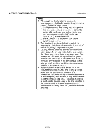
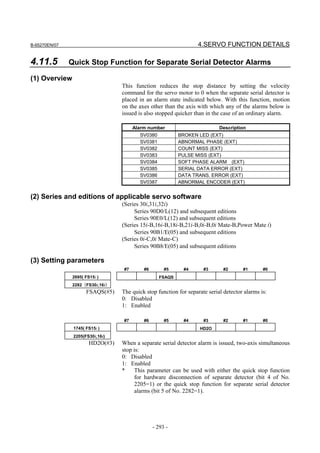
![4.SERVO FUNCTION DETAILS B-65270EN/07
4.11.6 Quick Stop Function at OVL and OVC Alarm
(1) Overview
This function reduces the stop distance for a servo motor when an
OVL (motor overheat or amplifier overheat) or OVC alarm condition
is detected for the servo motor. It also causes the other axes to stop
sooner than they would when a usual alarm occurs.
(2) Series and editions of applicable servo software
(Series 30i,31i,32i)
Series 90D0/A(01) and subsequent editions
Series 90E0/A(01) and subsequent editions
(Series 15i-B,16i-B,18i-B,21i-B,0i-B,0i Mate-B,Power Mate i)
Series 9096/A(01) and subsequent editions
Series 90B0/A(01) and subsequent editions
Series 90B1/A(01) and subsequent editions
Series 90B6/A(01) and subsequent editions
(Series 0i-C,0i Mate-C,20i-B)
Series 90B5/A(01) and subsequent editions
(3) Setting parameters
#7 #6 #5 #4 #3 #2 #1 #0
2600 (FS15i) OVQK
2212 (FS30i, 16i)
OVQK (#7) Specifies whether to enable quick stop function at the OVC and OVL
alarm as follows:
0: To disable
1: To enable
NOTE
The operation of this function is performed by using
part of the unexpected disturbance torque
detection function. Therefore, to use this function,
the option for the “unexpected disturbance torque
detection function” is required.
1976 (FS15i) Brake control timer
2083 (FS30i, 16i)
[Unit of data] ms
[Setting value] 100
- 294 -](https://image.slidesharecdn.com/b-65270en07-121129013640-phpapp01/85/B-65270-en-07-304-320.jpg)
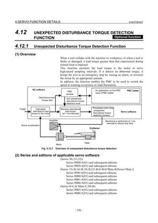
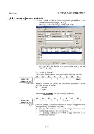
![4.SERVO FUNCTION DETAILS B-65270EN/07
<4> Set up the parameters related to the observer.
1862 (FS15i) Observer gain
2050 (FS30i, 16i)
• When HRV1, HRV2, or HRV3 control is used:
[Standard setting value] 956 → To be changed to 3559.
• When HRV4 control is used:
[Standard setting value] 264 → To be changed to 1420
1863 (FS15i) Observer gain
2051 (FS30i, 16i)
• When HRV1, HRV2, or HRV3 control is used:
[Standard setting value] 510 → To be changed to 3329.
• When HRV4 control is used:
[Standard setting value] 35 → To be changed to 332
NOTE
When using this function together with the
observer, do not modify the standard setting of the
parameter above.
Observer:
Bit 2 of No.1808 (Series 15i)
Bit 2 of No.2003 (Series 30i, 16i, and so on)
<5> Make adjustments on the POA1 observer parameter.
1859 (FS15i) Observer parameter (POA1)
2047 (FS30i, 16i)
Turn the servo motor to perform linear back and forth operation at a
speed equal to about 50% of the rapid traverse rate, and observe the
motor speed (SPEED) and the estimated disturbance value (DTRQ).
The waveform observed before the adjustment should show one of the
following features:
Motor velocity
Estimated
disturbance
value
Insufficient POA1 value Excessive POA1 value
At acceleration: At acceleration:
Undershoot on estimated Overshoot on estimated
disturbance value disturbance value
At deceleration: At deceleration:
Overshoot on estimated Undershoot on estimated
disturbance value disturbance value
- 298 -](https://image.slidesharecdn.com/b-65270en07-121129013640-phpapp01/85/B-65270-en-07-308-320.jpg)
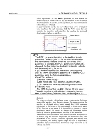
![4.SERVO FUNCTION DETAILS B-65270EN/07
<6> For the vertical axis, adjust the torque offset. (This is
unnecessary for the horizontal axis.)
For the vertical axis, the estimated disturbance value is not
centered at level 0. Torque offset adjustment is done to center the
estimated disturbance value at level 0.
1980 (FS15i) Torque offset parameter
2087 (FS30i, 16i)
[Unit of data] TCMD unit (7282 with the maximum current value of the amplifier)
[Valid data range] -7282 to 7282
(Example of torque offset setting)
Estimated disturbance values for constant-velocity movements in
the + direction and - direction are read. In the figure below,
minimum value A (signed) is read in a movement in the +
direction, and maximum value B (signed) is read in a movement
in the - direction. A torque offset parameter setting is given using
the following expressions:
A [Ap] + B [Ap]
Torque offset = × 3641
Maximum amplifier current value [Ap]
Estimated disturbance
value level 0
6.6A
Maximum
value B
Estimated disturbance
Minimum value center line
value A Influence by gravity
If you read the minimum value A and maximum value as –8.6 [Ap]
and –4.5 [Ap] in the above chart (the amplifier used is rated at 80 [Ap]
maximum), the torque offset parameter = -[(-8.6)+(-4.5)]/80×3641 =
596. The following chart applies when the parameter is set with 596.
- 300 -](https://image.slidesharecdn.com/b-65270en07-121129013640-phpapp01/85/B-65270-en-07-310-320.jpg)
![B-65270EN/07 4.SERVO FUNCTION DETAILS
When the torque offset parameter is set, be sure to set the following
parameter to 1.
#7 #6 #5 #4 #3 #2 #1 #0
2603 (FS15i) TCPCLR
2215 (FS30i, 16i)
TCPCLR(#1) The function for setting a value for canceling the torque offset at an
emergency stop in the velocity loop integrator is:
0: Disabled
1: Enabled
<7> Compensate for dynamic friction.
(i) Method of canceling a dynamic friction in proportion to
velocity
Measure an estimated disturbance value at a constant
velocity. Then, by assuming this measured value as a
dynamic friction, set the proportional coefficient for a
velocity and dynamic friction compensation value.
1727 (FS15i) Dynamic friction compensation coefficient
2116 (FS30i, 16i)
[Unit of data] See the equation below.
[Valid data range] 0 to 264 (Series 9096, Series 90B0/A(01) to D(04) editions)
-264 to 264 (Series 90B0/E(05) and subsequent editions, Series 90B1,
Series 90B5, Series 90B6, Series 90B8, Series 90D0, or Series 90E0)
[Measurement velocity] Rotary motor: 1000 min-1, Linear motor: 1000 mm/s
Measure an estimated disturbance value at a measurement velocity,
then set the results of calculations made according to the table below.
Dynamic friction Estimated disturbance value [Ap]
= × 440
compensation coefficient Maximum amplifier current value [Ap]
NOTE
If the measurement velocity is too high, lower the
measurement velocity, and measure the estimated
disturbance value. By proportional calculation,
obtain the estimated disturbance value at the
above measurement velocity.
Dynamic friction compensation value
No.1727(Series 15i)
No.2116(Series 16i and
so on)
Dynamic friction
compensation coefficient
Velocity
-1
1000 min (rotary motor)
1000 mm/s (linear motor)
Set a compensation value at a measurement
velocity, and correct the value proportional to the
velocity as a dynamic friction.
- 301 -](https://image.slidesharecdn.com/b-65270en07-121129013640-phpapp01/85/B-65270-en-07-311-320.jpg)
![4.SERVO FUNCTION DETAILS B-65270EN/07
(Example of setting for a rotary motor)
- Suppose that the estimated disturbance value at 1000 min-1 is 1
[Ap] (the maximum amplifier current value is 40 [Ap]).
Dynamic friction compensation coefficient = 1/40 × 440 = 11
Dynamic friction compensation Dynamic friction compensation
before setting after setting
Read value
A(A)
These portions represent The effect of dynamic friction is
disturbances due to dynamic reduced, and stable estimated
friction. An adjustment is made to disturbance values are obtained.
eliminate these portions.
(ii) Method of setting a dynamic friction as "portion
proportional to velocity + constant portion" and imposing a
limit
If the compensation value for stop time to low-velocity
movement is insufficient in adjustment of (i), set a dynamic
friction compensation value in the stop state. If the
compensation value for high-speed movement is excessive,
a limit is imposed on the compensation value.
Dynamic friction compensation value
No.2759(Series 15i)
No.2346(Series 16i and
so on) No.1727(Series 15i)
Compensation limit value No.2116(Series 16i and
No.2758(Series 15i) so on)
No.2345(Series 16i and so Dynamic friction
compensation coefficient
on)
Compensation value in the
1000min-1 Velocity
stop time
Set a compensation value in the stop time and
a compensation limit value in addition to a
compensation value at 1000 min-1.
- 302 -](https://image.slidesharecdn.com/b-65270en07-121129013640-phpapp01/85/B-65270-en-07-312-320.jpg)
![B-65270EN/07 4.SERVO FUNCTION DETAILS
NOTE
This method can be used with the following servo
software:
(Series 30i, 31i, 32i)
Series 90D0/A(01) and subsequent editions
Series 90E0/A(01) and subsequent editions
(Series 15i-B, 16i-B, 18i-B, 21i-B, 0i-B, 0i Mate-B,
Power Mate i)
Series 90B0/E(05) and subsequent editions
Series 90B1/A(01) and subsequent editions
Series 90B6/A(01) and subsequent editions
(Series 0i-C, 0i Mate-C, 20i-B)
Series 90B5/A(01) and subsequent editions
Series 90B8/A(01) and subsequent editions
2758 (FS15i) Dynamic friction compensation value in the stop state
2345 (FS30i, 16i)
[Unit of data] TCMD unit (7282 when the estimated disturbance value is equivalent
to the maximum current value of the amplifier)
[Valid data range] 0 to 7282
[Measurement velocity] 10 min-1 (rotary motor), 10 mm/s (linear motor)
The absolute value of a setting is used.
2759 (FS15i) Dynamic friction compensation limit value
2346 (FS30i, 16i)
[Unit of data] TCMD unit (7282 when the estimated disturbance value is equivalent
to the maximum current value of the amplifier)
[Valid data range] 0 to 7282
[Measurement velocity] Maximum feedrate
The absolute value of a setting is used.
(Method of setting)
First, measure an estimated disturbance value when a movement
is made at a maximum feedrate on the axis, then set the results of
calculations made according to the table below in "dynamic
friction compensation limit value".
Dynamic friction |Estimated disturbance value [Ap]|
= × 7282
compensation limit value Maximum amplifier current value [Ap]
Next, measure an estimated disturbance value when a movement
is made on the axis at the measurement velocity (10 min-1 or 10
mm/s) for "dynamic friction compensation value in the stop
state", then set the results of calculations made according the
table below in "dynamic friction compensation value in the stop
state".
Dynamic friction |Estimated disturbance value [Ap]|
compensation value in = × 7282
Maximum amplifier current value [Ap]
the stop state
- 303 -](https://image.slidesharecdn.com/b-65270en07-121129013640-phpapp01/85/B-65270-en-07-313-320.jpg)
![4.SERVO FUNCTION DETAILS B-65270EN/07
Finally, measure an estimated disturbance value when a
movement is made on the axis at the measurement velocity (1000
min-1 or 1000 mm/s) for "dynamic friction compensation
coefficient", then set the results of calculations made according
the table below in "dynamic friction compensation coefficient".
Dynamic friction |Estimated disturbance value [Ap]|
= × 440
compensation coefficient Maximum amplifier current value [Ap]
<8> Set an unexpected disturbance torque detection alarm level.
Perform several different operations (sample machining program,
simultaneous all-axis rapid traverse acc./dec., etc.), and observe
estimated disturbance values, and measure the maximum
(absolute) value.
Then, set up an alarm level.
+ Estimated disturbance value
0
Maximum
value
-
1997 (FS15i) Unexpected disturbance torque detection alarm level
2104 (FS30i, 16i)
Alarm level conversion uses the following expression.
Unexpected disturbance torque detection alarm level =
|Estimated disturbance value [Ap]|
× 7282+500 to 1000 approximately
Maximum amplifier current value [Ap]
NOTE
1 Add some margin (usually about 500 to 1000) to
the alarm level to be set.
2 If the "unexpected disturbance torque detection
alarm level" parameter is 32767, no unexpected
disturbance torque alarm detection is performed.
<9> Set a distance to be retraced at unexpected disturbance torque
detection.
If the retrace amount parameter is 0, the motor stops at the point
where an unexpected disturbance torque was detected. To retract
the tool from the location of collision quickly, set the retrace
distance parameter.
- 304 -](https://image.slidesharecdn.com/b-65270en07-121129013640-phpapp01/85/B-65270-en-07-314-320.jpg)
![B-65270EN/07 4.SERVO FUNCTION DETAILS
Conceptual diagram illustrating retrace
The tool plunges in at full torque.
No unexpected disturbance torque
detected
The tool go beyond slightly, and returns to
Unexpected disturbance torque the location where the unexpected
detected, but no retrace is performed. disturbance torque was detected.
Unexpected disturbance torque The tool is retracted from the location where
detected, and retrace is performed. the unexpected disturbance torque was
detected to avoid mechanical contact at the
Retrace distance ultimate stop position.
Collision Unexpected disturbance
torque detected
1996 (FS15i) Retrace distance
2103 (FS30i, 16i)
[Unit of data] Detection unit
[Setting value] Approximately 3 mm
NOTE
When the tool is moving faster or slower than the
velocity listed below, the tool will not go back even
if this parameter is set. It stops at the location
where an unexpected disturbance torque was
detected.
Let the value set in the retrace distance parameter
be A:
Minimum retract velocity =
A × detection unit (µm) × 60/512 [mm/min]
Example)
When detection unit = 1 µm, and retract amount
setting = 3000, the minimum velocity at which
the tool is retracted is:
Minimum retract velocity =
3000 × 1 × 60/512 = 352 [mm/min]
[2-axis simultaneous retract function at detection of an
unexpected disturbance torque]
Usually, retraction at detection of an unexpected disturbance torque is
performed only on the axis with which the unexpected disturbance
torque is detected. However, when an unexpected disturbance torque
is detected on one position tandem axis, retraction can be performed
on the other position tandem axis as well by setting the parameter
below.
(Series and editions of applicable servo software)
(Series 30i,31i,32i)
Series 90D0/A(01) and subsequent editions
Series 90E0/A(01) and subsequent editions
- 305 -](https://image.slidesharecdn.com/b-65270en07-121129013640-phpapp01/85/B-65270-en-07-315-320.jpg)
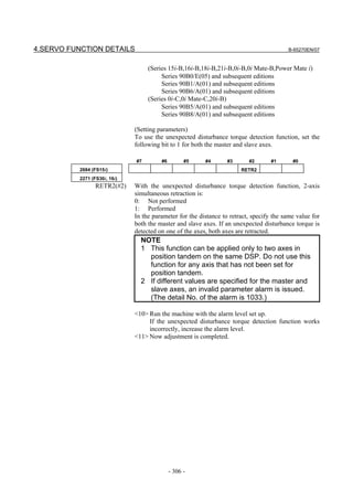
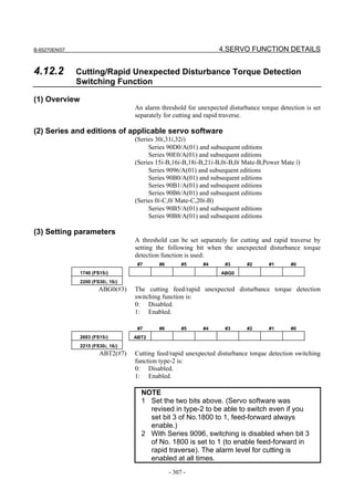
![4.SERVO FUNCTION DETAILS B-65270EN/07
Alarm thresholds for unexpected disturbance torque detection are set
in the following parameters:
1997 (FS15i) Unexpected disturbance torque detection threshold for cutting
2104 (FS30i, 16i) (This parameter is used both in not switching mode and in switching mode.)
[Valid data range] 0 to 7282
1765 (FS15i) Unexpected disturbance torque detection threshold for rapid traverse
2142 (FS30i, 16i)
[Valid data range] 0 to 7282
NOTE
1 When the alarm level for cutting is 32767,
unexpected disturbance torque detection is not
performed during cutting.
2 When the alarm level for rapid traverse is 32767,
unexpected disturbance torque detection is not
performed during rapid traverse. When both
parameters are 32767, unexpected disturbance
torque detection is not performed at any time.
- 308 -](https://image.slidesharecdn.com/b-65270en07-121129013640-phpapp01/85/B-65270-en-07-318-320.jpg)
![B-65270EN/07 4.SERVO FUNCTION DETAILS
4.12.3 Unexpected Disturbance Torque Detection Switching
Function Depending on Acc.
(1) Overview
This function separately sets a threshold level for unexpected
disturbance torque alarms detected in an acceleration/deceleration
zone where the estimated disturbance value tends to fluctuate. This
function can protect against erroneous detection of an unexpected
disturbance torque alarm in an acceleration/deceleration zone.
1. In a zone where acceleration/deceleration is performed (zone
where extensive acceleration is applied), a higher alarm level can
be set.
2. The influence of acceleration after positioning can be avoided by
setting a timer when returning to the original alarm level after
alarm level switching.
(2) Series and editions of applicable servo software
(Series 30i,31i,32i)
Series 90D0/P(16) and subsequent editions
Series 90E0/P(16) and subsequent editions
(Series 15i-B,16i-B,18i-B,21i-B,0i-B,0i Mate-B,Power Mate i)
Series 90B1/H(08) and subsequent editions
(Series 0i-C,0i Mate-C,20i-B)
Series 90B8/H(08) and subsequent editions
(3) Notes
• When using this function, set the post-acceleration timer (No. 2358).
• This function can be used together with the cutting/rapid unexpected
disturbance torque detection switching function.
(4) Setting parameters
(Related parameters)
2755 (FS15i) Acceleration threshold in unexpected disturbance torque detection
2342 (FS16i ,30i)
[Unit of data] Detection unit
[Setting value] Let α [mm/s2] be an acceleration rate and let P [mm/pulse] be a
detection unit. Then, the value to be set in the parameter can be found
from the following expression:
α × 64
Setting = (Series 15i, 16i, etc.)
P × 106
α × 16
= (Series 30i)
P × 106
[Valid data range] 0 to 32767
When 0 is set in this parameter, acceleration-based alarm level
switching is disabled.
- 309 -](https://image.slidesharecdn.com/b-65270en07-121129013640-phpapp01/85/B-65270-en-07-319-320.jpg)
![4.SERVO FUNCTION DETAILS B-65270EN/07
2756 (FS15i) Alarm level for high acceleration in unexpected disturbance torque
detection
2343 (FS16i ,30i)
[Unit of data] TCMD
[Valid data range] 0 to 32767
When the absolute value of a specified acceleration rate is equal to or
greater than the setting of No. 2342, the setting of No. 2343 is applied
as an unexpected disturbance torque detection alarm level.
When 0 is set in this parameter, acceleration-based alarm level
switching is disabled.
2771 (FS15i) Post-acceleration timer in unexpected disturbance torque detection
2358 (FS16i ,30i)
[Unit of data] ms
[Valid data range] 0 to 32767
This parameter maintains a changed alarm level for a timer-set period
even after the specified acceleration rate is reduced below a certain
level.
Velocity
<1> Specified acceleration rate is
Acceleration lower than acceleration
threshold (No. 2342).
No.2342
<2> Period set in post-acceleration
timer (No. 2358) has elapsed.
Alarm level
No.2343
<3> Level returns to level for low
acceleration.
No.2104 or No.2142
No.2358 Time
- 310 -](https://image.slidesharecdn.com/b-65270en07-121129013640-phpapp01/85/B-65270-en-07-320-320.jpg)
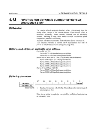
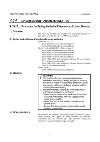
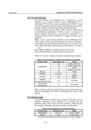
![4.SERVO FUNCTION DETAILS B-65270EN/07
NOTE
1 For details of the linear encoders usable with
FANUC linear motors, refer to "FANUC LINEAR
MOTOR LiS series DESCRIPTIONS
(B-65382EN)".
2 For details of the linear encoders, contact the
manufacturer of each linear encoder.
3 To use servo HRV4 control with a linear motor, a
detector that supports servo HRV4 control is
needed. See "(d) Detector" in "(4) Servo HRV4
control hardware" of Subsection 4.2.2.
(5) Parameter settings
Set the parameters according to the procedure below. Note the points
below when setting the parameters.
[Cautions for using incremental linear encoders]
The following parameter setting procedure involves a parameter
to be specified according to the resolution of the linear encoder.
If an incremental linear encoder is to be used, convert the
encoder signal pitch to the resolution for parameter calculation,
using the following equation.
Resolution [µm] = Encoder signal pitch [µm] / 512
Parameter setting procedure (1)
Procedure (1) can be used to initialize the parameters (such as current
gain) necessary to drive a linear motor. After initialization, parameters
depending on the linear encoder resolution (or the value obtained by
dividing the signal pitch of the linear encoder by the interpolation
magnification of the position detection circuit) must be set. Set these
parameters by following parameter setting procedure (2).
Parameters related to initialization
For incremental type, For absolute type
#7 #6 #5 #4 #3 #2 #1 #0
1804 (FS15i) DGPR PLC0
2000 (FS30i, 16i)
DGPR(#1) Set 0. (After initialization, this bit is set to 1 automatically.)
For PLCO (#0), see Table 4.14.1(d) and Table 4.14.1(e).
1806 (FS15i) AMR
2001 (FS30i, 16i)
Specify 00000000.
1879 (FS15i) Movement direction
2022 (FS30i, 16i)
- 314 -](https://image.slidesharecdn.com/b-65270en07-121129013640-phpapp01/85/B-65270-en-07-324-320.jpg)
![B-65270EN/07 4.SERVO FUNCTION DETAILS
(a) When the coil slider is movable:
+111: When the positive direction is specified, the slider moves
in the positive direction.
-111: When the positive direction is specified, the slider moves
in the reverse direction.
Power line Positive
direction
Slider movable
Magnet plate fixed
(b) When the magnet plate is movable:
+111: When the positive direction is specified, the magnet plate
moves in the positive direction.
-111: When the positive direction is specified, the magnet plate
moves in the reverse direction.
Power line
Positive Slider fixed
direction
Magnet plate movable
Motor ID number
For incremental type, For absolute type
1874 (FS15i) Motor ID number
2020 (FS30i, 16i)
Standard parameters are prepared for the linear motors listed below as
of July, 2007. When the standard parameters are not included in the
servo software used, see the parameter list shown in this manual, and
set the parameters.
[200-V driving]
Motor 90B6 90D0
Motor model Motor ID No. 90B1
specification 90B5 90E0
LiS300A1/4 0441-B200 351 B(02) B(02) G(07)
LiS600A1/4 0442-B200 353 B(02) B(02) G(07)
LiS900A1/4 0443-B200 355 B(02) B(02) G(07)
LiS1500B1/4 0444-B210 357 B(02) B(02) G(07)
LiS3000B2/2 0445-B110 360 B(02) B(02) G(07)
LiS3000B2/4 0445-B210 362 B(02) B(02) G(07)
LiS4500B2/2 0446-B110 364 B(02) B(02) G(07)
LiS6000B2/2 0447-B110 368 B(02) B(02) G(07)
LiS6000B2/4 0447-B210 370 B(02) B(02) G(07)
LiS7500B2/2 0448-B110 372 B(02) B(02) G(07)
LiS7500B2/4 0448-B210 374 B(02) B(02) G(07)
LiS9000B2/2 0449-B110 376 B(02) B(02) G(07)
LiS9000B2/4 0449-B210 378 B(02) B(02) G(07)
- 315 -](https://image.slidesharecdn.com/b-65270en07-121129013640-phpapp01/85/B-65270-en-07-325-320.jpg)
![4.SERVO FUNCTION DETAILS B-65270EN/07
Motor 90B6 90D0
Motor model Motor ID No. 90B1
specification 90B5 90E0
LiS3300C1/2 0451-B110 380 B(02) B(02) G(07)
LiS9000C2/2 0454-B110 384 B(02) B(02) G(07)
LiS11000C2/2 0455-B110 388 B(02) B(02) G(07)
LiS15000C2/2 0456-B110 392 B(02) B(02) G(07)
LiS15000C2/3 0456-B210 394 B(02) B(02) G(07)
LiS10000C3/2 0457-B110 396 B(02) B(02) G(07)
LiS17000C3/3 0459-B110 400 B(02) B(02) G(07)
The motor ID numbers are for SERVO HRV2. Loading is possible
with the servo software of the series and edition listed above or
subsequent editions.
[400-V driving]
Motor 90B6 90D0
Motor model Motor ID No. 90B1
specification 90B5 90E0
LiS1500B1/4 0444-B210 358 B(02) B(02) G(07)
LiS3000B2/2 0445-B110 361 B(02) B(02) G(07)
LiS4500B2/2HV 0446-B010 363 B(02) B(02) G(07)
LiS4500B2/2 0446-B110 365 B(02) B(02) G(07)
LiS6000B2/2HV 0447-B010 367 B(02) B(02) G(07)
LiS6000B2/2 0447-B110 369 B(02) B(02) G(07)
LiS7500B2/HV2 0448-B010 371 B(02) B(02) G(07)
LiS7500B2/2 0448-B110 373 B(02) B(02) G(07)
LiS9000B2/2 0449-B110 377 B(02) B(02) G(07)
LiS3300C1/2 0451-B110 381 B(02) B(02) G(07)
LiS9000C2/2 0454-B110 385 B(02) B(02) G(07)
LiS11000C2/2HV 0455-B010 387 B(02) B(02) G(07)
LiS11000C2/2 0455-B110 389 B(02) B(02) G(07)
LiS15000C2/3HV 0456-B010 391 B(02) B(02) G(07)
LiS10000C3/2 0457-B110 397 B(02) B(02) G(07)
LiS17000C3/2 0459-B110 401 B(02) B(02) G(07)
The motor ID numbers are for SERVO HRV2. Loading is possible
with the servo software of the series and edition listed above or
subsequent editions.
NOTE
For the motor ID number of the conventional
models, see Appendix G.
After parameter initialization, check that the function bit for linear
motor control is set to 1 (linear motor control is enabled).
#7 #6 #5 #4 #3 #2 #1 #0
1954(FS15i) LINEAR
2010(FS30i,16i)
LINEAR(#2) Linear motor control is:
0: Disabled
1: Enabled
- 316 -](https://image.slidesharecdn.com/b-65270en07-121129013640-phpapp01/85/B-65270-en-07-326-320.jpg)
![B-65270EN/07 4.SERVO FUNCTION DETAILS
When using position detection circuit H or C for linear motor
For incremental type
When a position detection circuit having an interpolation
magnification of 2048 is used with an incremental type linear encoder,
the parameter shown below must be set to maintain both the maximum
feedrate and high resolution. Set the parameter before proceeding to
procedure (2).
Series and editions of applicable servo software
(Series 30i,31i,32i)
Series 90D0/A(01) and subsequent editions
Series 90E0/A(01) and subsequent editions
(Series 15i-B,16i-B,18i-B,21i-B,Power Mate i)
Series 90B0/Q(17) and subsequent editions
Series 90B1/A(01) and subsequent editions
Series 90B6/A(01) and subsequent editions
(Series 0i-C, 20i-B)
Series 90B5/A(01) and subsequent editions
To use a linear motor position detection circuit (A860-2033-T20*,
-T30*), the servo software of the following series and editions is need:
(Series 30i,31i,32i)
Series 90D0/P(16) and subsequent editions
Series 90E0/P(16) and subsequent editions
(Series 15i-B,16i-B,18i-B,21i-B,Power Mate i)
Series 90B1/K(11) and subsequent editions
#7 #6 #5 #4 #3 #2 #1 #0
2687(FS15i) HP2048
2274(FS30i,16i)
HP2048(#0) A circuit having an interpolation magnification of 2048 (position
detection circuit H or C for linear motor) is:
0: Not used
1: Used
NOTE
1 Setting this parameter(No.2274(FS30i,16i) or
No.2687(FS15i)) to "enable" lets you make the
basic parameter settings as explained in Procedure
(2).
2 Changing this parameter results in a power-off
alarm being raised.
3 When this parameter is set, the detection unit in the
case of FFG=1/1 is (signal pitch/512 [um]).
If a minimum detection unit (signal pitch/2048 [µm])
is necessary, specify:
FFG = 4/1
- 317 -](https://image.slidesharecdn.com/b-65270en07-121129013640-phpapp01/85/B-65270-en-07-327-320.jpg)
![4.SERVO FUNCTION DETAILS B-65270EN/07
NOTE
4 If nano-interpolation is applied, a resolution as high
as (signal pitch/2048 [µm]) is applied as
decimal-part feedback.
5 When a linear encoder of incremental type is used,
a linear motor pole detector is needed.
6 With position detection circuit H for linear motor,
the interpolation magnification can be changed
using setting pin SW3. (The setting at the time of
shipment is Setting B.)
Setting A: The interpolation magnification is 512.
Setting B: The interpolation magnification is 2048.
Setting A enables up to high-speed operation, and
Setting B enables high resolution feedback
acquisition.
Setting A Setting B
HP2048 1 1
Resolution [µm] ※1 λ [µm]/128 *2 λ [µm]/ 512 *2
Maximum velocity
λ [µm] × 122880 *2 λ [µm] × 30720 *2
[mm/min]
(*1) The resolution values in the table above are
used for calculation of various parameters.
(*2) λ [mm] represents a linear scale signal pitch.
7 When the position detection circuit C for linear
motor is used, no function is available which can
change an interpolation magnification according to
a set-up pin. (Fixed at a magnification of 2048)
Linear motor position detection circuit C is
connected to the scale with an absolute address
origin.
- 318 -](https://image.slidesharecdn.com/b-65270en07-121129013640-phpapp01/85/B-65270-en-07-328-320.jpg)
![B-65270EN/07 4.SERVO FUNCTION DETAILS
Parameter setting procedure (2)
For incremental type, For absolute type
Procedure (2) makes parameter settings that depend on the resolution
of the linear encoder (hereafter simply called "the resolution"). Set the
parameters according to Table 4.14.1 (d), (e).
When using an incremental type linear encoder, calculate as follows:
Resolution [µm] = encoder signal pitch [µm] / 512
The pole-to-pole span used in calculation varies, depending on the
motor model.
• Small linear motors: 30 mm (LiS300A, LiS600A, LiS900A)
• Medium-size and large linear motors: 60 mm (models other than
the above)
(See Table 4.14.1(c).)
#7 #6 #5 #4 #3 #2 #1 #0
1804 (FS15i) PLC0
2000 (FS30i, 16i)
PLC0(#0) The number of velocity pulses and the number of position pulses are:
0: Used without being modified.
1: Used after being multiplied by 10
If the number of velocity pulses is lager than 32767, set the parameter
to 1.
If the number of position pulses exceeds 32767, use the following
position pulse conversion coefficient.
1876 (FS15i) Number of velocity pulses
2023 (FS30i, 16i)
(Parameter calculation expression)
Number of velocity pulses = 3125 / 16 / (resolution [µm])
If the calculation result is greater than 32767, set up PLC0 = 1, and set
the parameter (PULCO) with a value of 1/10.
1891 (FS15i) Number of position pulses
2024 (FS30i, 16i)
(Parameter calculation expression)
Number of position pulses = 625 / (resolution [µm])
If the calculation result is greater than 32767, determine the parameter
setting (PPLS), using the following position pulse conversion
coefficient (PSMPYL).
- 319 -](https://image.slidesharecdn.com/b-65270en07-121129013640-phpapp01/85/B-65270-en-07-329-320.jpg)
![4.SERVO FUNCTION DETAILS B-65270EN/07
2628 (FS15i) Position pulses conversion coefficient
2185 (FS30i, 16i)
This parameter is used if the calculated number of position pulses is
greater than 32767.
(It can be specified in the Series 90B0, 90B1, 90B6, 90B5, 90D0, or
90E0.)
(Parameter calculation expression)
PLC0 = 0 → The parameter is set so that the following equation
holds: (the number of position pulses) × (position
pulses conversion coefficient) = 625/resolution [µm].
PLC0 = 1 → The parameter is set so that the following equation
holds: 10 × (the number of position pulses) × (position
pulses conversion coefficient) = 625/resolution [µm].
(→ See Supplementary 3 of Subsection 2.1.8.)
#7 #6 #5 #4 #3 #2 #1 #0
1707 (FS15i) APTG
2013 (FS30i, 16i)
APTG(#7) When using an absolute type linear encoder, set this bit to:
1: Ignores an α Pulsecoder soft disconnection.
Setting AMR conversion coefficients
Calculate the number of feedback pulses per pole-to-pole span of the
linear motor, and find AMR conversion coefficients 1 and 2 expressed
by the equation shown below.
Number of pulses per pole-to-pole span
= pole-to-pole span [mm] × 1000/resolution [µm]
= (AMR conversion coefficient 1) × 2(AMR conversion coefficient 2)
1705 (FS15i) AMR conversion coefficient 1
2112 (FS30i, 16i)
1761 (FS15i) AMR conversion coefficient 2
2138 (FS30i, 16i)
Supplementary)
If AMR conversion coefficient 1 = (pole-to-pole span [mm]/
resolution [µm]) is an integer and a multiple of 1024, setting of
only AMR conversion coefficient 1 is needed. In this case, the
following are assumed:
AMR conversion coefficient 1
= (pole-to-pole span [mm]/resolution [µm])
AMR conversion coefficient 2 = 0
The pole-to-pole span depends on the motor model as indicated in the
table below.
Table 4.14.1 (c) List of pole-to-pole spans
Classification Pole-to-pole span (D) Motor model
Small motors 30mm LiS300A, LiS600A, LiS900A
Medium-size and
60mm Model other than the above
large motors
- 320 -](https://image.slidesharecdn.com/b-65270en07-121129013640-phpapp01/85/B-65270-en-07-330-320.jpg)
![B-65270EN/07 4.SERVO FUNCTION DETAILS
1977 (FS15i) Flexible feed gear numerator
2084 (FS30i, 16i)
1978 (FS15i) Flexible feed gear denominator
2085 (FS30i, 16i)
Use a unified detection unit for the flexible feed gear (FFG)
parameters according to Tables 4.14.1 (d) and 4.14.1 (e).
(Parameter calculation expression)
FFG = (resolution [µm]) / (detection unit [µm])
Table 4.14.1 (d) Parameter setting when an incremental type linear encoder is used
[Medium-size and large motors] (pole-to-pole span: 60mm)
Number of velocity pulses / FFG(No.2084/No.2085)
AMR conversion
PLC0 Number of position pulses,
Signal pitch coefficient 1 or 2 0.1-µm
(2000#0) Conversion coefficient 1-µm detection
(No.2112, 2138) detection
(No.2023 / No.2024, 2185)
20 0 5000 / 16000, 0 3000, 9 5 / 128 50 / 128
40 0 2500 / 8000, 0 1500, 9 5 / 64 50 / 64
2 1 5000 / 8000, 2 30000, 9 1 / 256 10 / 256
4 1 2500 / 8000, 0 15000, 9 1 / 128 10 / 128
40.513167 0 2468 / 7899, 0 1481, 9 301 / 3804 3010 / 3804
[Small motors] (pole-to-pole span: 30mm)
Number of velocity pulses / FFG(No.2084/No.2085)
AMR conversion
PLC0 Number of position pulses,
Signal pitch coefficient 1 or 2 0.1-µm
(2000#0) Conversion coefficient 1-µm detection
(No.2112, 2138) detection
(No.2023 / No.2024, 2185)
20 0 5000 / 16000, 0 1500, 9 5 / 128 50 / 128
40 0 2500 / 8000, 0 750, 9 5 / 64 50 / 64
2 1 5000 / 8000, 2 15000, 9 1 / 256 10 / 256
4 1 2500 / 8000, 0 7500, 9 1 / 128 10 / 128
40.513167 0 2468 / 7899, 0 1481, 8 301 / 3804 3010 / 3804
* The parameter Nos. for the Series 15i are omitted. See the
previous page.
Table 4.14.1 (e) Parameter setting when an absolute type linear encoder is used
[Medium-size and large motors] (pole-to-pole span: 60mm)
Number of velocity pulses / FFG(No.2084/No.2085)
AMR conversion
PLC0 Number of position pulses,
Resolution coefficient 1 or 2 0.1-µm
(2000#0) Conversion coefficient 1-µm detection
(No.2112, 2138) detection
(No.2023 / No.2024, 2185)
0.1 0 1953 / 6250, 0 9375, 6 1/10 1/1
0.05 0 3906 / 12500, 0 9375, 7 1/20 1/2
[Small motors] (pole-to-pole span: 30mm)
Number of velocity pulses / FFG(No.2084/No.2085)
AMR conversion
PLC0 Number of position pulses,
Resolution coefficient 1 or 2 0.1-µm
(2000#0) Conversion coefficient 1-µm detection
(No.2112, 2138) detection
(No.2023 / No.2024, 2185)
0.1 0 1953 / 6250, 0 9375, 5 1/10 1/1
0.05 0 3906 / 12500, 0 9375, 6 1/20 1/2
* The parameter Nos. for the Series 15i are omitted. See the
previous page.
- 321 -](https://image.slidesharecdn.com/b-65270en07-121129013640-phpapp01/85/B-65270-en-07-331-320.jpg)
![4.SERVO FUNCTION DETAILS B-65270EN/07
(Cautions)
If the encoder signal pitch is larger than 200 µm, various coefficients
used in the servo software may overflow to raise an alarm on invalid
parameters, because the setting for the number of velocity pulses
becomes very small.
In this case, change the corresponding parameter by referencing
Subsection 2.1.8, "Measures for Alarms on Illegal Servo Parameter
Settings."
Parameter setting procedure (3)
When a linear motor is used, the linear encoder must be installed so
that the Z phase of the linear encoder matches the origin of the
activating phase. Otherwise, the specified motor characteristics cannot
be obtained. (For details of installation positions, refer to "FANUC
LINEAR MOTOR LiS series DESCRIPTIONS (B-65382EN)".)
Procedure (3) describes the method of adjusting the activating phase
origin (AMR offset adjustment) when it is difficult to install a linear
encoder at a specified position with a specified precision.
Setting the AMR offset
For incremental type, For absolute type
• When the learning control function is used (Series 90B3 and
90B7), see "Learning Function Operator's Manual".
• When the learning control function is not used (Series 9096,
90B0, 90B6, 90B5, 90D0, and 90E0), set the AMR offset as
follows:
1762 (FS15i) AMR offset
2139 (FS30i, 16i)
Specifies an activating phase (AMR offset) for phase Z.
[Unit of data] Degrees
[Valid data range] -45 to +45 (*)
(*) Extended AMR offset setting range (-60 degrees to +60 degrees)
can be specified by setting the parameter below. So, if the AMR
offset value does not lie within the range -45 degrees to +45
degrees in adjustment processing, set the bit below. (Usually, set
the bit below to 0.)
(Series 9096 and Series 90B0/B(02) and earlier editions are not
supported.)
#7 #6 #5 #4 #3 #2 #1 #0
2683 (FS15i) AMR60
2270 (FS30i, 16i)
AMR60 (#0) Changes the AMR offset setting range.
0: -45 degrees to +45 degrees (standard setting range)
1: -60 degrees to +60 degrees (extended setting range)
- 322 -](https://image.slidesharecdn.com/b-65270en07-121129013640-phpapp01/85/B-65270-en-07-332-320.jpg)