2. CONTENTS:
1) Valve sizing selection criteria
2) Valve sizing nomenclature
3) Body sizing of liquid service
control valves
4) Body sizing of gas service control
valves
3. VALVE SIZING SELECTION CRITERIA
For correct sizing, the following conditions
are needed:
1. Upstream pressure
2. Maximum and minimum temperatures
3. Type of process fluid
4. Flow rate that is based upon the maximum
flow rate, the average flow rate, and the
minimum flow rate
5. Vapor pressure
4. VALVE SIZING SELECTION CRITERIA
7. Pipeline size, schedule, and material
8. Maximum, average, and minimum
pressure drop
9. Specific gravity of the fluid
10. the critical pressure.
5. VALVE SIZING NOMENCLATURE
1. Upstream and Downstream Pressures:
✓ In order for the process to flow in a particular direction
through a valve, the upstream (P1) and downstream
pressures (P2) must be different.
✓ If P1=P2→ no flow will occur.
✓ Upstream pressure (P1) is the pressure reading
taken before the valve.
✓ Downstream pressure (P2) is the pressure reading
taken after the valve.
6. 2. Pressure Drop/Pressure Differential:
✓ The difference between the upstream and
downstream pressures, ∆P=P1-P2.
✓ The pressure drop allows for the flow of fluid through
the process system from the upstream side of the
valve to the downstream side.
✓ ∆P , Flow through the valve.
7. 3. Flow Capacity:
✓ Valve coefficient (Cv) numerically equal to the number of U.S. Gallons
of water at 60°F that will flow through the valve in one minute with 1.0 psi
pressure drop.
✓ When calculated properly, Cv determines the correct trim size (or area of
the valve’s restriction) that will allow the valve to pass the required flow
while allowing stable control of the process throughout the stroke of the
valve.
8. 4. Actual Pressure Drop
✓is defined as the difference between the upstream
(inlet) and downstream (outlet) pressures.
✓When the choked and actual pressure drops are
compared and the actual pressure drop is smaller, it is
used in the Cv sizing equation.
9. 5. Choked Pressure Drop
✓ where further increases in the pressure drop will not change the valve’s flow
rate. This is what is commonly called choked flow.
✓ Because of the choked condition, the flow rate will reach a maximum condition
due to the existence of cavitation in liquids or sonic velocity with gases.
✓ the term choked pressure drop, ∆Pchoked is used to show the theoretical
point where choked flow occurs, intersecting the linear lines of the constant Cv
and the maximum flow rate Qmax.
✓ This point is known as the liquid pressure-recovery factor FL.
✓ For gas applications, the terminal pressure-drop ratio xT is used to describe the
choked pressure drop for a particular valve.
10. 6. Allowable Pressure Drop
✓ The allowable pressure drop, ∆Pa is chosen from the
smaller of the actual pressure drop or the choked
pressure drop and is used in the determination of the
correct Cv
✓ Should be used in the determination of the Cv in liquid
application when:
➢ first, if the inlet pressure P1 is fairly close to the
vapor pressure.
➢ second, if the outlet pressure P2 is fairly close to the
vapor pressure;.
➢ third, if the actual pressure drop is fairly large when
compared to the inlet pressure P1.
11. 7. Cavitation
✓ when the fluid passes through the narrowest point of the valve (vena
contracta), the pressure decreases inversely as the velocity increases.
✓ If the pressure drops below the vapor pressure for that particular fluid,
vapor bubbles begin to form.
✓ As the fluid moves into a larger area of the vessel or downstream piping,
the pressure recovers to a certain extent. This increases the pressure
above the vapor pressure, causing the vapor bubbles to collapse or
implode.
✓ creation of the vapor bubbles and their subsequent implosion—is called
cavitation and is a leading cause of valve damage in the form of erosion
of metal surfaces.
12. 8. Flashing Issues
✓ When the downstream pressure does not recover
above the vapor pressure, the vapor bubbles
remain in the fluid and travel downstream from the
valve, creating a mixture of liquid and gas. This is
called flashing.
✓ Problems typically associated with flashing are
higher velocities and erosion of valve
components.
14. 9. Liquid Pressure-Recovery Factor (FL)
✓ Is a critical element in liquid sizing.
✓ predicts the effect the geometry of a valve’s body on the maximum
capacity of that valve.
✓ is used to predict the amount of pressure recovery occurring between
the vena contracta and the outlet of the body.
✓ The liquid pressure-recovery factor is determined by the manufacturer
through flow testing that particular valve style.
✓ FL factors can vary significantly depending on the internal design of the
valve.
✓ Generally, rotary valves, especially ball and butterfly valves, allow for a
high recovery of the fluid following the vena contracta. Therefore, they
tend to cavitate and choke at smaller pressure drops than globe valves.
✓ For the most part, globe valves have better FL factors and are able to
handle severe services when compared to rotary valves.
15. 10. Liquid Critical-Pressure Ratio Factor
✓ The liquid critical-pressure ratio factor FF is important
to liquid sizing because it predicts the theoretical
pressure at the vena contracta, when the
maximum effective pressure drop (or in other words,
the choked pressure drop) occurs across the valve.
16. 11. Choked Flow
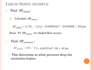
✓ the presence of cavitation or flashing expands the specific volume of the
fluid.
✓ The volume increases at a faster rate than if the flow increased due to the
pressure differential.
✓ At this point, the valve cannot pass any additional flow, even if the
downstream pressure is lowered.
✓ With gas and vapor services, choked flow occurs when the velocity of the
fluid achieves sonic levels (Mach 1 or greater).
✓ as the pressure decreases in the valve to pass through restrictions, velocity
increases inversely. As the pressure lowers, the specific volume of the fluid
increases to the point where a sonic velocity is achieved.
✓ Because of the velocity limitation [Mach 1 for gases and 50 ft/s (12.7 m/s)
for liquids], the flow rate is limited to that which is permitted by the sonic
velocity through the vena contracta or the downstream piping.
17. 12. Velocity
✓ As a general rule, smaller valve sizes are better equipped to
handle higher velocities than larger-sized valves.
✓ For liquid services, the general guideline for maximum
velocity at the valve outlet is 50 ft/s (12.7 m/s), while gas
services are generally restricted to Mach 1.0.
✓ When cavitation or flashing is present, creating a higher
velocity associated with the liquid–gas mixture, the
maximum velocity is usually restricted to 500 ft/s (127 m/s).
✓ In services where temperatures are close to saturation
point, the velocity must be less—approximately 30 ft/s (7.6
m/s). This lower velocity prevents the fluid from dropping
below the vapor pressure, which will lead to the formation of
vapor bubbles.
18. 13. Reynolds-Number Factor
✓ Some processes are characterized by nonturbulent
flow conditions in which laminar flow exists (such as
oils).
✓ Laminar fluids have high viscosity, operate in
lower velocities, or require a flow capacity
requirement that is extremely small.
✓ The Reynolds-number factor FR is used to correct
the Cv equation for these flow factors.
✓ In most cases, if the viscosity is fairly low (for
example, less than SAE 10 motor oil), the Reynolds-
number factor is insignificant.
19. 14. Piping-Geometry Factor
✓ The flow capacity of a valve may be affected
by nonstandard piping configurations, such
as the use of increasers or reducers, which
must be corrected in the Cv equation using
the piping-geometry factor FP.
✓ Standardized Cv testing is conducted by the
valve manufacturer with straight piping that is
the same line as the valve.
✓ The use of piping that is larger or smaller than
the valve, or the close proximity of piping
elbows, can decrease these values and must
be considered during sizing.
20. 15. Expansion Factor
✓ With gas services, the specific weight of the
fluid varies as the gas moves from the
upstream piping and through the valve to the
vena contracta.
✓ The expansion factor Y is used to
compensate for the effects of this change in
the specific weight of the gas.
✓ The expansion factor is important in that it
takes into account the changes in the cross-
sectional area of the vena contracta as the
pressure drop changes in that region.
21. 16. Ratio of Specific Heats Factor
✓ Because the Cv equation for gases is based upon
air, some adjustment must be made for other gases.
✓ The ratio of specific heats factor FK is used to adjust
the Cv equation to the individual characteristics of these
gases.
17. Terminal Pressure-Drop Ratio
✓ With gases, the point where the valve is choked (which
means that increasing the pressure drop though
lowering the downstream pressure cannot increase the
flow of the valve) is predicted by the terminal pressure-
drop ratio xT.
✓ is affected by the geometry of the valve’s body and
varies according to valve style and individual size.
22. 18. Compressibility Factor
✓ Because the density of gases varies
according to the temperature and pressure of
the fluid, the fluid’s compressibility must be
included in the Cv equation.
✓ Therefore the compressibility factor Z is
included in the equation and is a function of the
temperature and pressure.
23. LIQUID SIZING EXAMPLE
Consider the following service conditions:
Determine the appropriate valve size.
24. LIQUID SIZING EXAMPLE
1. Find the actual pressure drop.
2. Find ΔPchoked:
I. Find FL from Table 7.4
II. Calculate FF
Globe, flow-to-open
25. LIQUID SIZING EXAMPLE
2. Find ΔPchoked:
III. Calculate ΔPchoked
Since P< ΔPchoked , no choked flow occurs.
3. Find ΔPcavitation :
This determine at what pressure drop the
cavitation begins.
26. LIQUID SIZING EXAMPLE
4. Calculate Cv, at given SG & assuming Fp =1.0
5. Check the body valve using Table 7.2 (at the
calculated Cv):
2-in valve body would be the smallest size to
pass the required Cv (which is 33.4)
30. 8. Find new Cv:
9. Calculate the velocity through the valve:
I. Find Av using Table 7.9
Velocity of 51ft/s exceed the limit
Of 50 ft/s for liquids.
→Since the service is cavitating,
Damage will most likely occur to
Valve body.
→Option: Lower the velocity by
Choosing the next larger valve
size, a 3-in body, with Av = 7.07
31. Body sizing of gas service
control valves
Refer to Handout