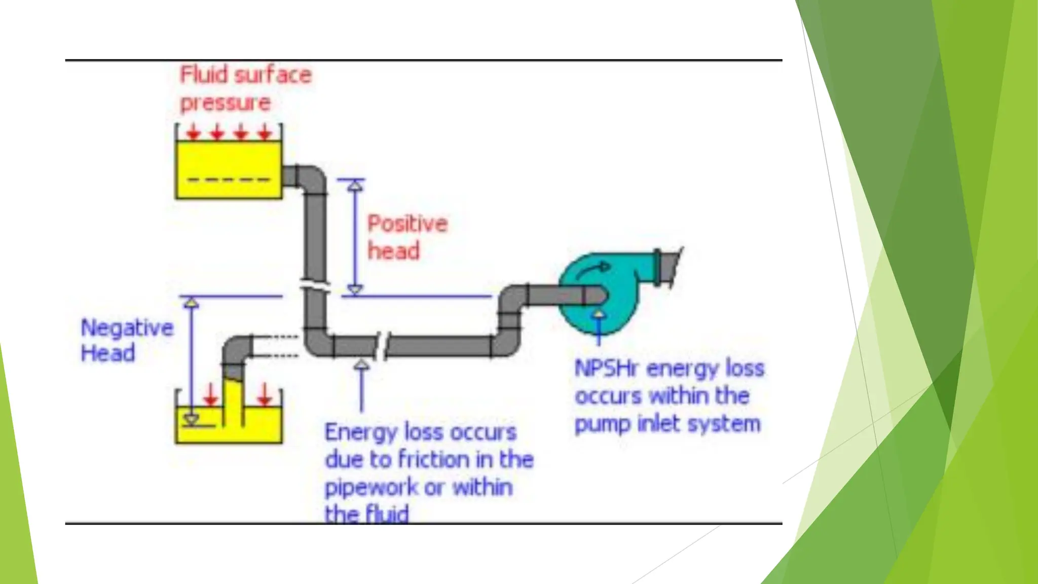
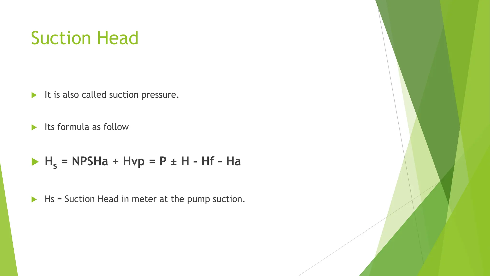
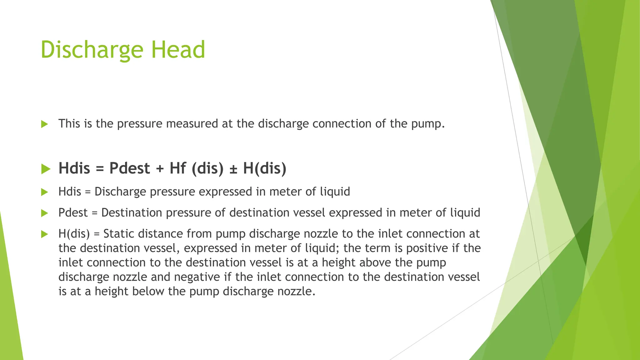
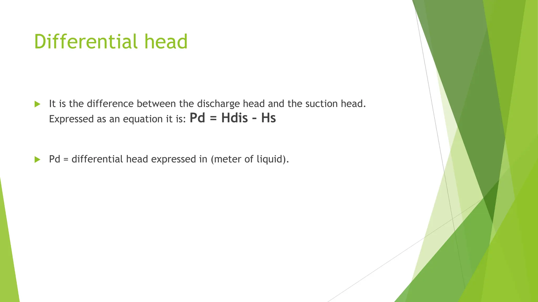
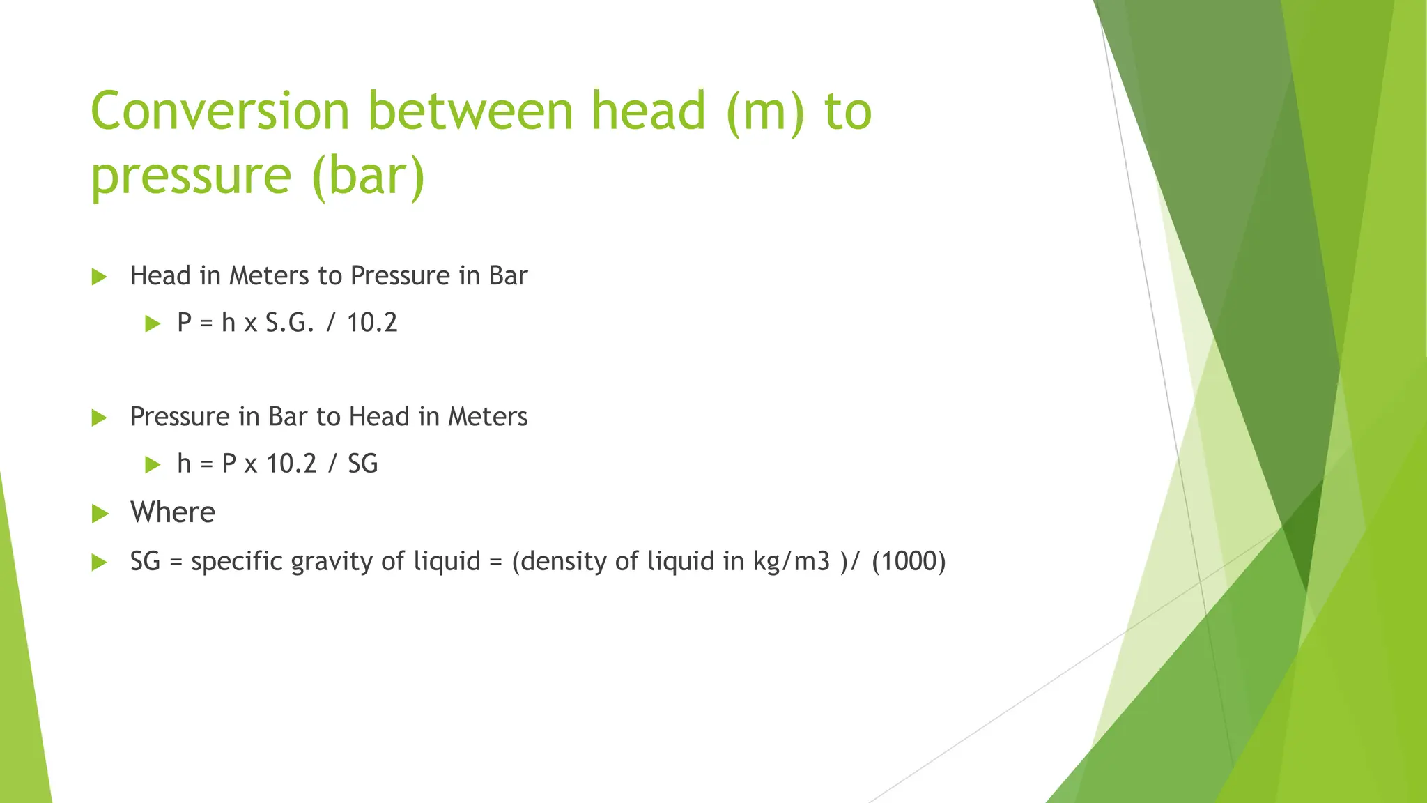
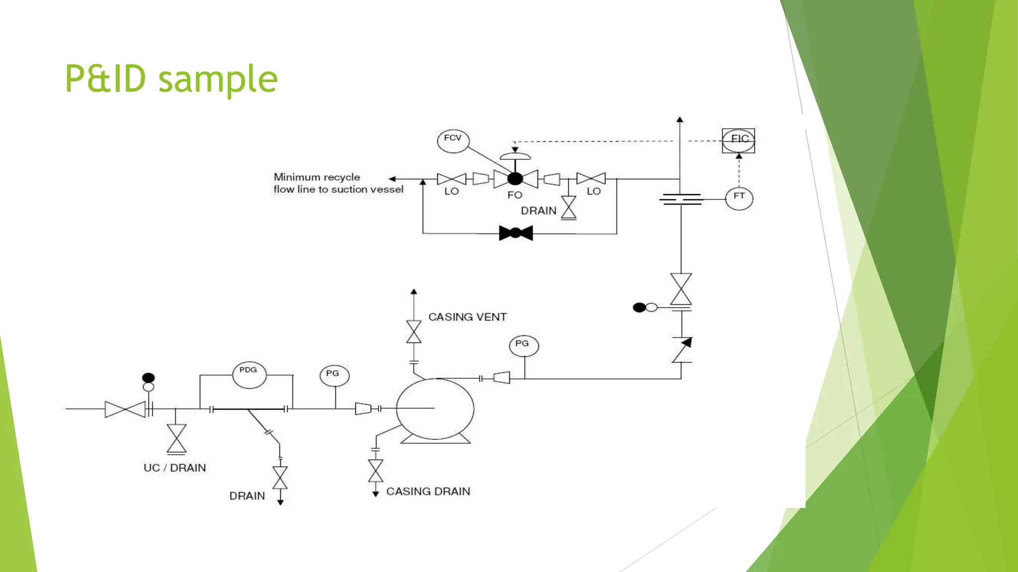
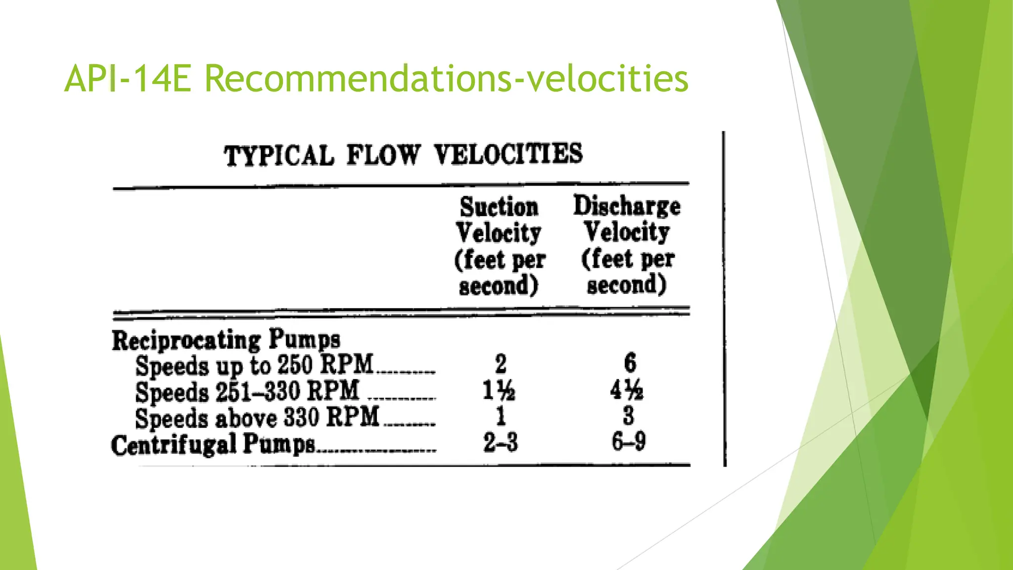
Ahmed Gamal
Jr. Process Engineer
ahmedgamalmetwaly3@gmail.com
PUMP HYDRAULIC CALCULATIONS
API-14E,GPSA and PEM
INDEX
 Net positive suction head available ( NPSHa )
 Suction Head
 Discharge Head
 Differential head
 Conversion between head (m) to pressure (bar)
 Aspen plus
 P&ID sample
 API-14E Recommendations
Net positive suction head available
( NPSHa )
NPSHa definition
 It is the suction head present at the pump suction over and above the vapor
pressure of the liquid.
 It is a function of the suction system and is independent of the type of pump
in the system.
 It is calculated by the engineer or pump user, and supplied to the pump
manufacturer as part of the pump specification.
NPSHa general formula
 NPSHa = P ± H - Hf - Hvp – Ha
 Where :-
 P :- absolute pressure on the surface of the liquid in the suction vessel,
expressed in meter of liquid.
 Hf = friction loss in the suction line, including all piping, valves, fittings,
filters, etc., expressed in meter of liquid; this term varies with flow, so NPSHa
must be calculated based on a particular flow rate.
NPSHa general formula cont..
 H = static distance from the surface of the liquid in the supply vessel to the
centerline of the pump impeller, in meter; the term is positive if the pump
has a static suction head, and negative if the pump has a static suction lift.
For the purpose of NPSHa calculations, both the static suction head and the
static suction lift should be considered at the “minimum operating liquid
level” of the suction vessel.
 Hvp = vapor pressure of the liquid at the pumping temperature, expressed in
meter of liquid.
 Ha = Acceleration head Acceleration head needs to be considered only for
reciprocating pumps. For centrifugal pumps and rotary pumps the
acceleration head is zero.
Suction Head
 It is also called suction pressure.
 Its formula as follow
 Hs = NPSHa + Hvp = P ± H - Hf – Ha
 Hs = Suction Head in meter at the pump suction.
Discharge Head
 This is the pressure measured at the discharge connection of the pump.
 Hdis = Pdest + Hf (dis) ± H(dis)
 Hdis = Discharge pressure expressed in meter of liquid
 Pdest = Destination pressure of destination vessel expressed in meter of liquid
 H(dis) = Static distance from pump discharge nozzle to the inlet connection at
the destination vessel, expressed in meter of liquid; the term is positive if the
inlet connection to the destination vessel is at a height above the pump
discharge nozzle and negative if the inlet connection to the destination vessel
is at a height below the pump discharge nozzle.
Differential head
 It is the difference between the discharge head and the suction head.
Expressed as an equation it is: Pd = Hdis – Hs
 Pd = differential head expressed in (meter of liquid).
Conversion between head (m) to
pressure (bar)
 Head in Meters to Pressure in Bar
 P = h x S.G. / 10.2
 Pressure in Bar to Head in Meters
 h = P x 10.2 / SG
 Where
 SG = specific gravity of liquid = (density of liquid in kg/m3 )/ (1000)
Aspen plus
 If you have the eagerness to master pumps simulation in aspen plus, please
watch the below video
 Link : https://eiepd.com/pressure-change-in-aspen-plus/
P&ID sample
API-14E Recommendations
API-14E Recommendations-velocities
API-14E Recommendations-suction piping
 Suction piping should be one or two pipe sizes larger than the pump inlet
connection.
 Suction lines should be short with a minimum number of elbows and fittings
 Eccentric reducers should be used near the pump, with the flat side u % keep
the top of the line level. This eYirninates the possibility of gas pockets being
formed in the suction i in. If poten- tial for accumulation orcfebris is a con-
cern, means for removal is recommended.
 For reciprocating pumps, provide a suitable pulsation dampener (or make
provisions for adding a dampener at a later date) as close to the pump cylin-
der as possible.
API-14E Recommendations-discharge piping
 Discharge piping should be as short and direct as possible.
 Discharge piping should be one or two pipe sizes larger than pump discharge
connection.
 Velocity in discharge piping should not exceed three times the velocity in the
.suction piping. This velocity will nor- mally result in an economical line size
for all pumps, and will minimize pulsations in RC pumps.
 For reciprocating pumps, include a suitable pulsation dampener (or make
provisions for adding a dampener at a later date) as close to the pump cylin-
der as possible.
Thank you
Ahmed Gamal
Jr. Process Engineer

Pump Hydraulic Calculations API-14E, GPSA and PEM

  • 1.
    Ahmed Gamal Jr. ProcessEngineer ahmedgamalmetwaly3@gmail.com PUMP HYDRAULIC CALCULATIONS API-14E,GPSA and PEM
  • 2.
    INDEX  Net positivesuction head available ( NPSHa )  Suction Head  Discharge Head  Differential head  Conversion between head (m) to pressure (bar)  Aspen plus  P&ID sample  API-14E Recommendations
  • 3.
    Net positive suctionhead available ( NPSHa )
  • 4.
    NPSHa definition  Itis the suction head present at the pump suction over and above the vapor pressure of the liquid.  It is a function of the suction system and is independent of the type of pump in the system.  It is calculated by the engineer or pump user, and supplied to the pump manufacturer as part of the pump specification.
  • 5.
    NPSHa general formula NPSHa = P ± H - Hf - Hvp – Ha  Where :-  P :- absolute pressure on the surface of the liquid in the suction vessel, expressed in meter of liquid.  Hf = friction loss in the suction line, including all piping, valves, fittings, filters, etc., expressed in meter of liquid; this term varies with flow, so NPSHa must be calculated based on a particular flow rate.
  • 6.
    NPSHa general formulacont..  H = static distance from the surface of the liquid in the supply vessel to the centerline of the pump impeller, in meter; the term is positive if the pump has a static suction head, and negative if the pump has a static suction lift. For the purpose of NPSHa calculations, both the static suction head and the static suction lift should be considered at the “minimum operating liquid level” of the suction vessel.  Hvp = vapor pressure of the liquid at the pumping temperature, expressed in meter of liquid.  Ha = Acceleration head Acceleration head needs to be considered only for reciprocating pumps. For centrifugal pumps and rotary pumps the acceleration head is zero.
  • 8.
    Suction Head  Itis also called suction pressure.  Its formula as follow  Hs = NPSHa + Hvp = P ± H - Hf – Ha  Hs = Suction Head in meter at the pump suction.
  • 9.
    Discharge Head  Thisis the pressure measured at the discharge connection of the pump.  Hdis = Pdest + Hf (dis) ± H(dis)  Hdis = Discharge pressure expressed in meter of liquid  Pdest = Destination pressure of destination vessel expressed in meter of liquid  H(dis) = Static distance from pump discharge nozzle to the inlet connection at the destination vessel, expressed in meter of liquid; the term is positive if the inlet connection to the destination vessel is at a height above the pump discharge nozzle and negative if the inlet connection to the destination vessel is at a height below the pump discharge nozzle.
  • 10.
    Differential head  Itis the difference between the discharge head and the suction head. Expressed as an equation it is: Pd = Hdis – Hs  Pd = differential head expressed in (meter of liquid).
  • 11.
    Conversion between head(m) to pressure (bar)  Head in Meters to Pressure in Bar  P = h x S.G. / 10.2  Pressure in Bar to Head in Meters  h = P x 10.2 / SG  Where  SG = specific gravity of liquid = (density of liquid in kg/m3 )/ (1000)
  • 12.
    Aspen plus  Ifyou have the eagerness to master pumps simulation in aspen plus, please watch the below video  Link : https://eiepd.com/pressure-change-in-aspen-plus/
  • 13.
  • 14.
  • 15.
  • 16.
    API-14E Recommendations-suction piping Suction piping should be one or two pipe sizes larger than the pump inlet connection.  Suction lines should be short with a minimum number of elbows and fittings  Eccentric reducers should be used near the pump, with the flat side u % keep the top of the line level. This eYirninates the possibility of gas pockets being formed in the suction i in. If poten- tial for accumulation orcfebris is a con- cern, means for removal is recommended.  For reciprocating pumps, provide a suitable pulsation dampener (or make provisions for adding a dampener at a later date) as close to the pump cylin- der as possible.
  • 17.
    API-14E Recommendations-discharge piping Discharge piping should be as short and direct as possible.  Discharge piping should be one or two pipe sizes larger than pump discharge connection.  Velocity in discharge piping should not exceed three times the velocity in the .suction piping. This velocity will nor- mally result in an economical line size for all pumps, and will minimize pulsations in RC pumps.  For reciprocating pumps, include a suitable pulsation dampener (or make provisions for adding a dampener at a later date) as close to the pump cylin- der as possible.
  • 18.
    Thank you Ahmed Gamal Jr.Process Engineer