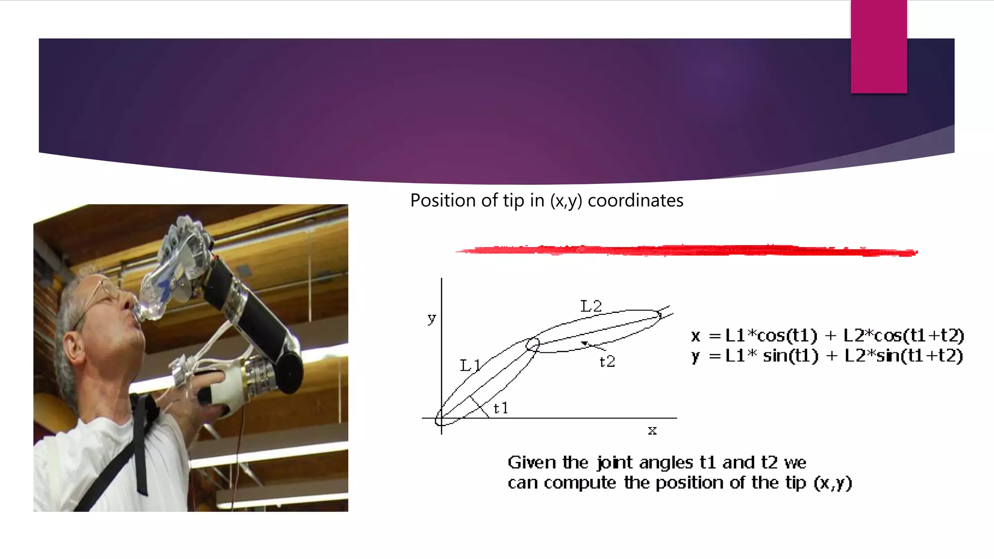
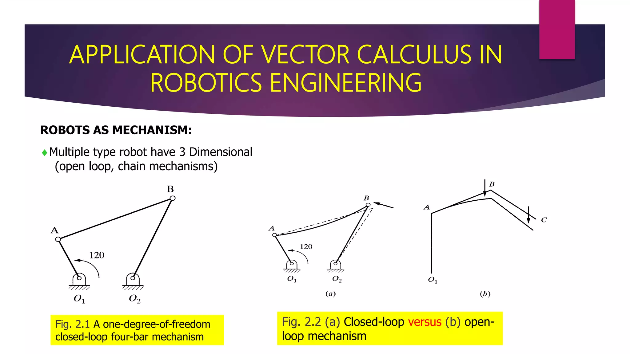
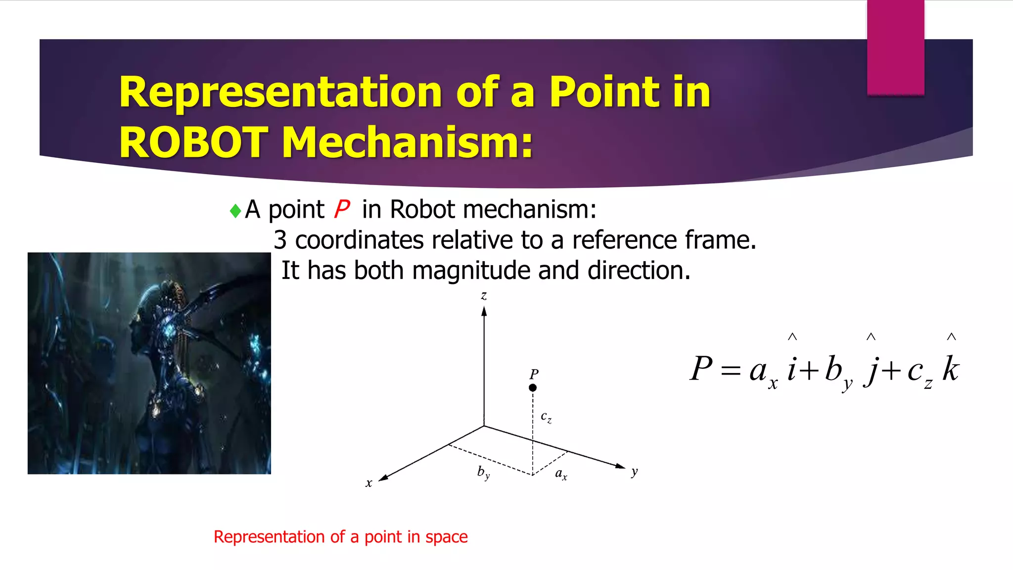
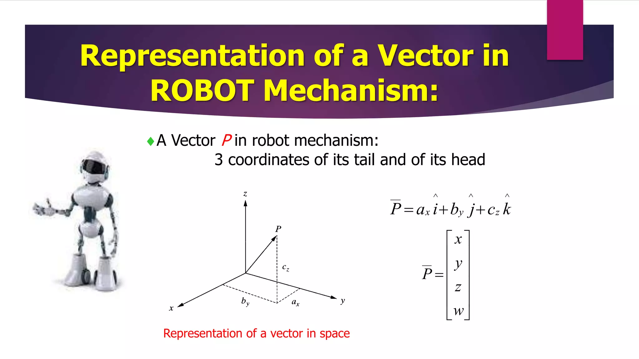
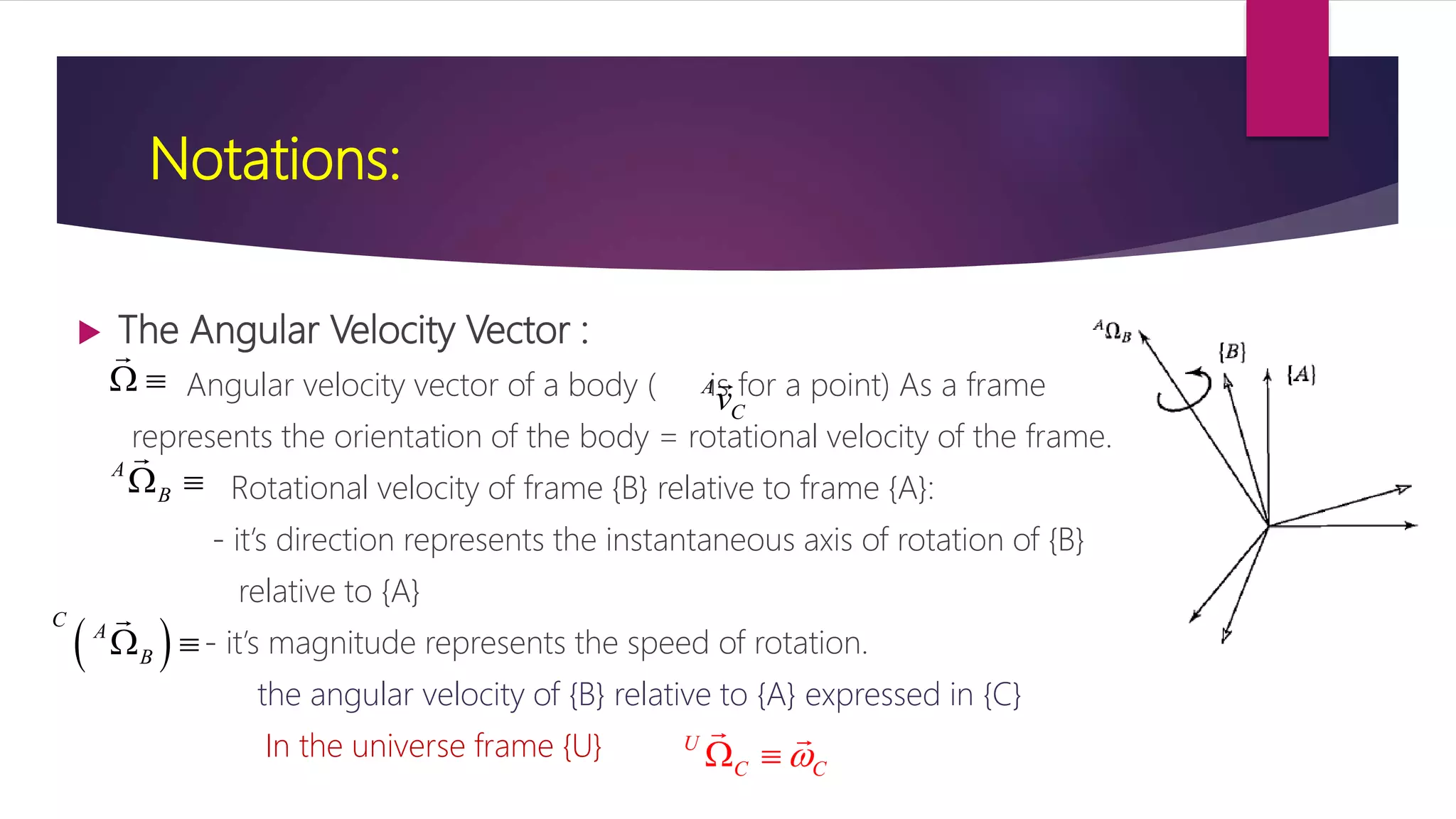
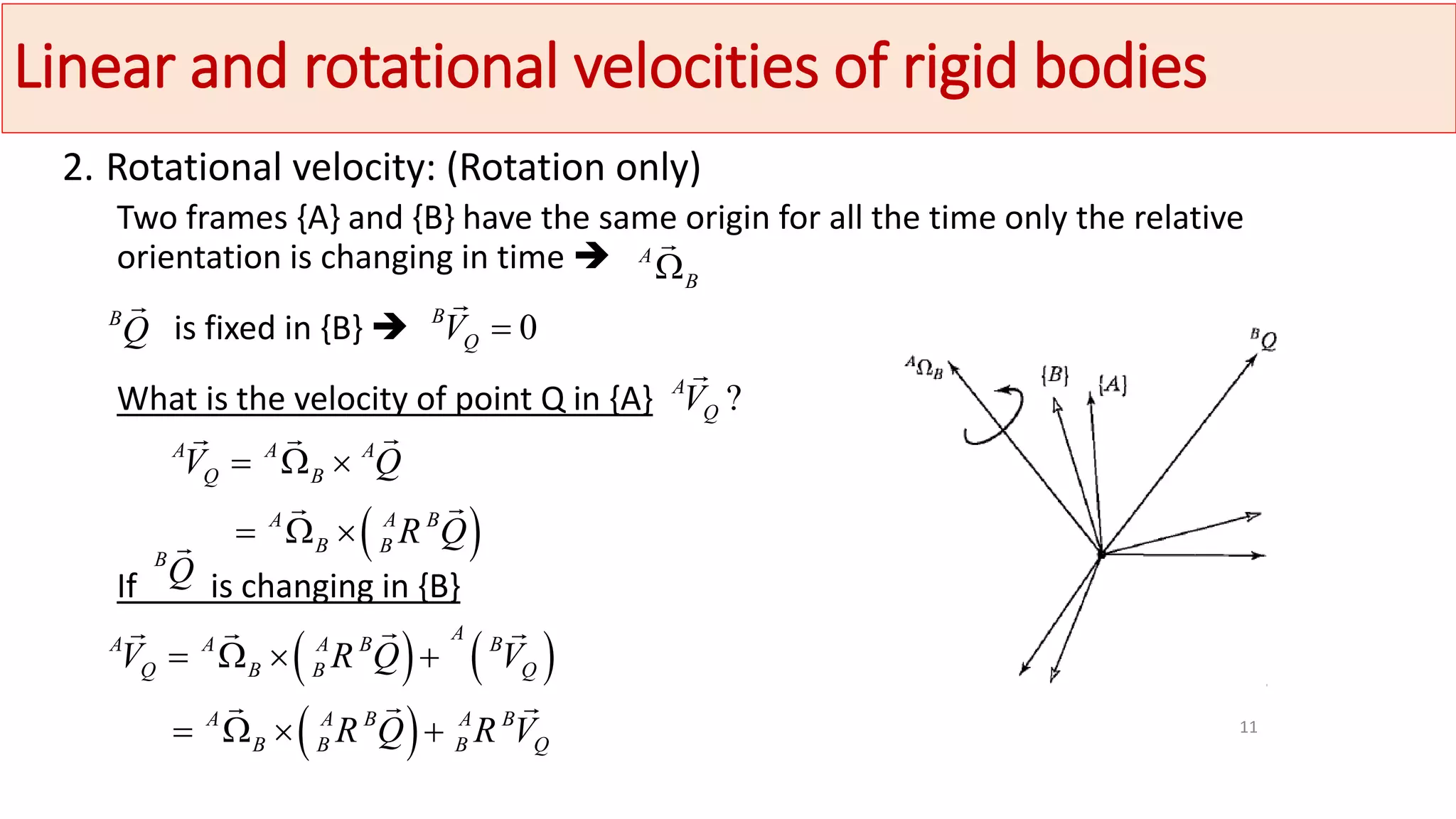
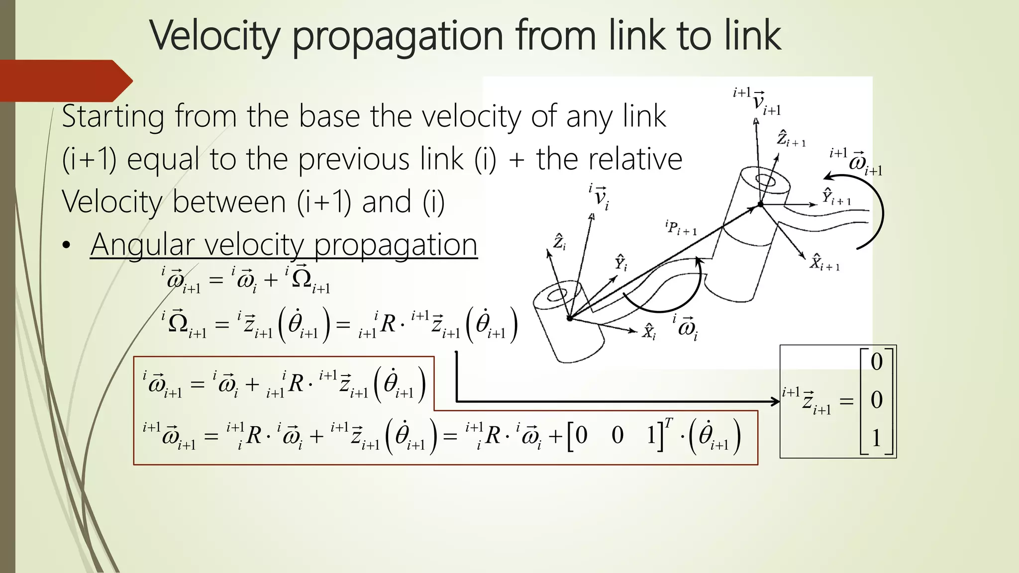
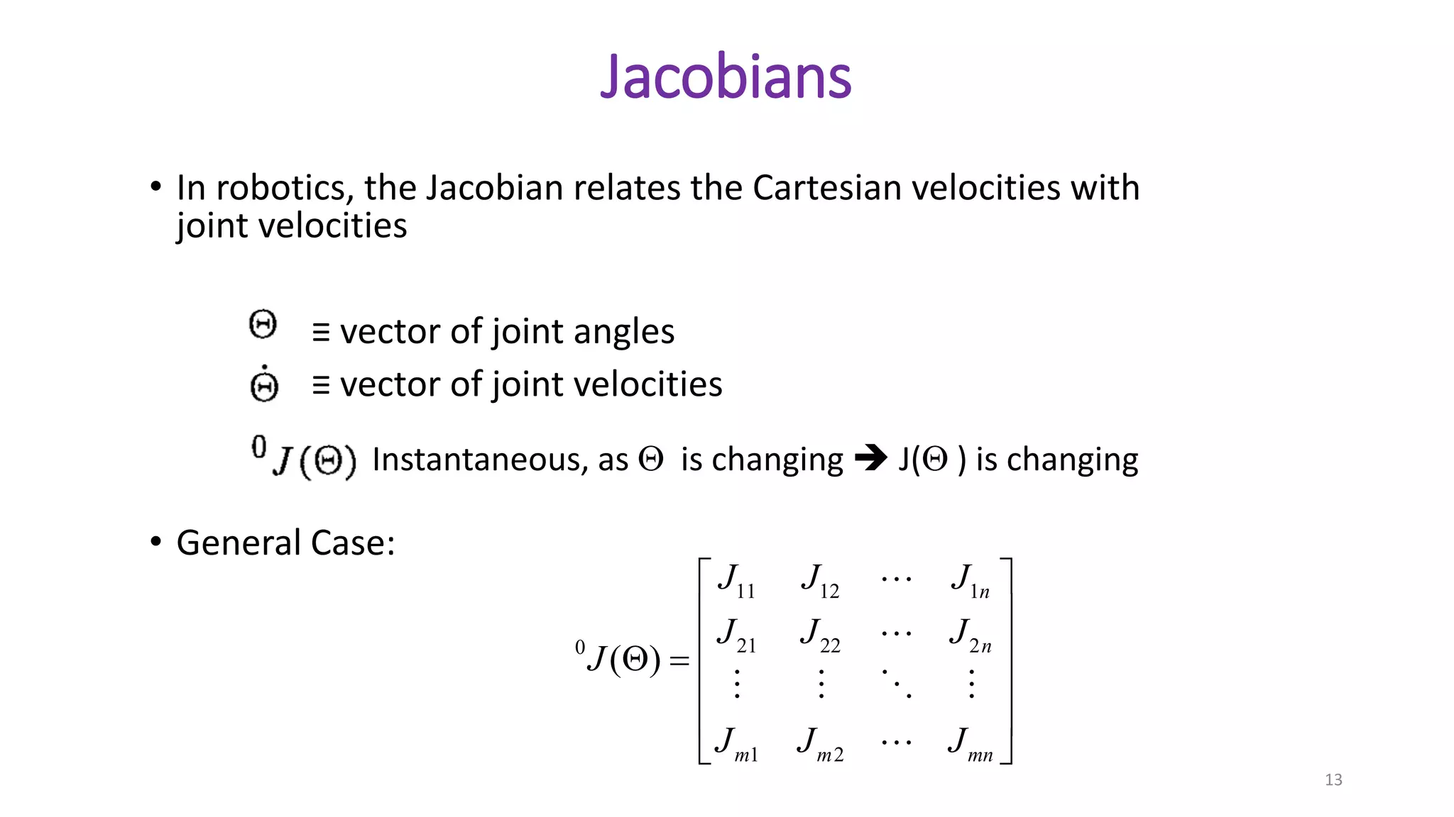
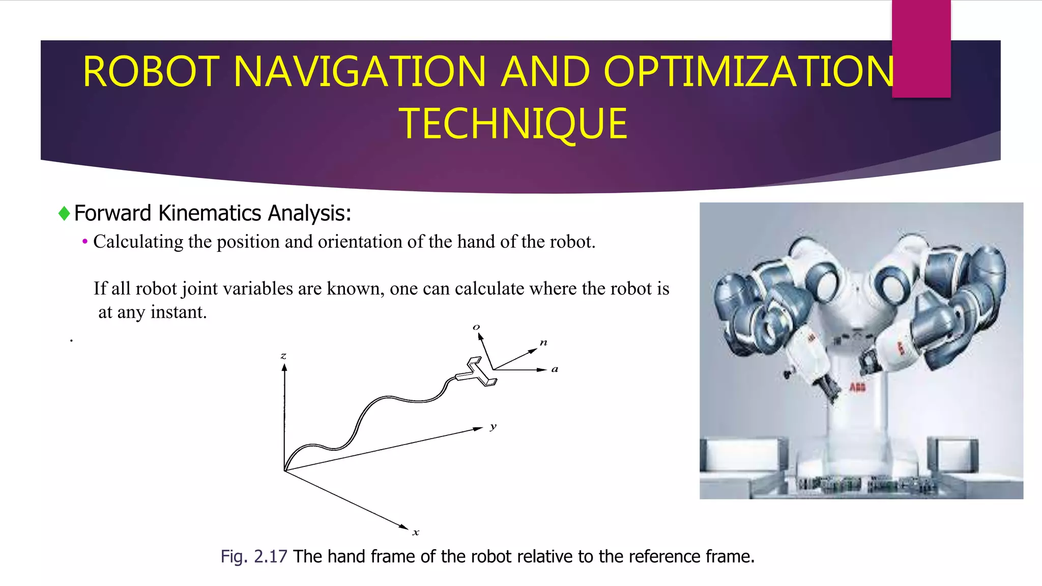
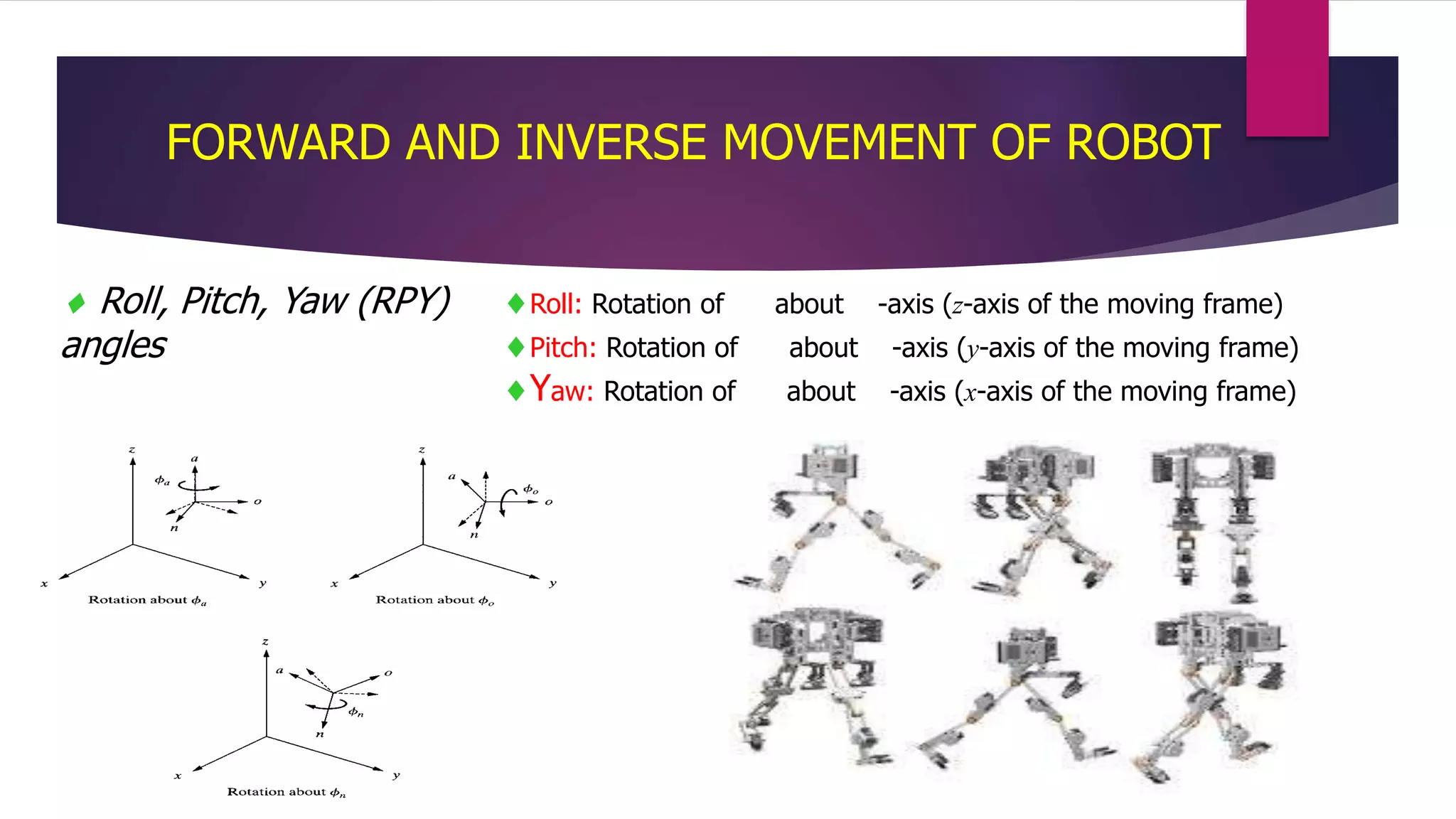
APPLICATION OF VECTOR CALCULUS IN
ROBOTICS ENGINEERING
PRESENTED BY:-
NAVEEN A
SAISARAN K
ROOPESH P
PAAVAI ENGINEERING COLLEGE, (AUTONOMOUS) NAMAKKAL.
INTRODUCTION:
 Vector Calculus was developed by J. Willard
Gibbs.
 He was born on February 11 1839 United States.
 He studied at the Yale University.
 He is the founder of vector calculus.
 He died on April 28 1903.
VECTOR CALCULUS:
 Vector Calculus is a branch of mathematics concerned with differentiation
and integration of vector fields. Vector has both magnitude and direction.
The term “VECTOR CALCULUS” is sometimes used as a synonym for the
broader subject of multivariable calculus, which includes vector calculus as
well as partial differentiation and multiple integration.
 In vector calculus, various differential operators defined on scalar
or vector fields are studied, which are typically expressed in terms
of the del operator.
= (∂⁄∂x, ∂⁄∂y, ∂⁄∂z)
Do you know how the
VECTOR CALCULUS is
applied in ROBOTICS?
Movement Imitation - Example
vector calculus in robotics for the research path integration in robot
Navigation and path optimization technique using vector calculus.
Future technology in vector graphics is a humanoid robot.
VECTOR CALCULUS IN ROBOTICS
Position of tip in (x,y) coordinates
APPLICATION OF VECTOR CALCULUS IN
ROBOTICS ENGINEERING
ROBOTS AS MECHANISM:
Multiple type robot have 3 Dimensional
(open loop, chain mechanisms)
Fig. 2.1 A one-degree-of-freedom
closed-loop four-bar mechanism
Fig. 2.2 (a) Closed-loop versus (b) open-
loop mechanism
Representation of a Point in
ROBOT Mechanism:
A point P in Robot mechanism:
3 coordinates relative to a reference frame.
It has both magnitude and direction.
^^^
kcjbiaP zyx 
Representation of a point in space
Representation of a vector in space
A Vector P in robot mechanism:
3 coordinates of its tail and of its head
^^^__
kcjbiaP zyx 













w
z
y
x
P
__
Representation of a Vector in
ROBOT Mechanism:
Notations:
 The Angular Velocity Vector :
Angular velocity vector of a body ( is for a point) As a frame
represents the orientation of the body = rotational velocity of the frame.
Rotational velocity of frame {B} relative to frame {A}:
- it’s direction represents the instantaneous axis of rotation of {B}
relative to {A}
- it’s magnitude represents the speed of rotation.
the angular velocity of {B} relative to {A} expressed in {C}
In the universe frame {U}
10
  A
Cv
A
B 
 
C
A
B 
U
C C 
Linear and rotational velocities of rigid bodies
2. Rotational velocity: (Rotation only)
Two frames {A} and {B} have the same origin for all the time only the relative
orientation is changing in time 
is fixed in {B} 
What is the velocity of point Q in {A}
If is changing in {B}
11
A
B
B
Q 0B
QV 
 
A A A
Q B
A A B
B B
V Q
R Q
  
  
B
Q
?A
QV
   
 
A
A A A B B
Q B B Q
A A B A B
B B B Q
V R Q V
R Q R V
   
   
Velocity propagation from link to link
i
i
1
1
i
iv

i
iv
1
1
i
i

Starting from the base the velocity of any link
(i+1) equal to the previous link (i) + the relative
Velocity between (i+1) and (i)
• Angular velocity propagation
   
1 1
1
1 1 1 1 1 1
i i i
i i i
i i i i
i i i i i iz R z
 
 
 

     
  
   
1
1
0
0
1
i
iz

 
 
 
  
 
     
1
1 1 1 1
1 1 1 1
1 1 1 10 0 1
i i i i
i i i i i
Ti i i i i i
i i i i i i i i
R z
R z R
  
    

   
   
   
  
      
Jacobians
• In robotics, the Jacobian relates the Cartesian velocities with
joint velocities
≡ vector of joint angles
≡ vector of joint velocities
• General Case:
13
Instantaneous, as  is changing  J( ) is changing
11 12 1
21 22 20
1 2
( )
n
n
m m mn
J J J
J J J
J
J J J
 
 
  
 
 
 
Fig. 2.17 The hand frame of the robot relative to the reference frame.
Forward Kinematics Analysis:
• Calculating the position and orientation of the hand of the robot.
If all robot joint variables are known, one can calculate where the robot is
at any instant.
.
ROBOT NAVIGATION AND OPTIMIZATION
TECHNIQUE
 Roll, Pitch, Yaw (RPY)
angles
Roll: Rotation of about -axis (z-axis of the moving frame)
Pitch: Rotation of about -axis (y-axis of the moving frame)
Yaw: Rotation of about -axis (x-axis of the moving frame)
FORWARD AND INVERSE MOVEMENT OF ROBOT
CONCLUSION:
We have presented a novel neural framework for robot
navigation in a cluttered environment.
“A MATHEMATICIAN IS A BLIND MAN IN A
DARK ROOM LOOKING FOR A BLACK CAT
WHICH ISN’T THERE.”
-CHARLES DARWIN
Thank
you

Vector calculus in Robotics Engineering

  • 1.
    APPLICATION OF VECTORCALCULUS IN ROBOTICS ENGINEERING PRESENTED BY:- NAVEEN A SAISARAN K ROOPESH P PAAVAI ENGINEERING COLLEGE, (AUTONOMOUS) NAMAKKAL.
  • 2.
    INTRODUCTION:  Vector Calculuswas developed by J. Willard Gibbs.  He was born on February 11 1839 United States.  He studied at the Yale University.  He is the founder of vector calculus.  He died on April 28 1903.
  • 3.
    VECTOR CALCULUS:  VectorCalculus is a branch of mathematics concerned with differentiation and integration of vector fields. Vector has both magnitude and direction. The term “VECTOR CALCULUS” is sometimes used as a synonym for the broader subject of multivariable calculus, which includes vector calculus as well as partial differentiation and multiple integration.  In vector calculus, various differential operators defined on scalar or vector fields are studied, which are typically expressed in terms of the del operator. = (∂⁄∂x, ∂⁄∂y, ∂⁄∂z)
  • 4.
    Do you knowhow the VECTOR CALCULUS is applied in ROBOTICS?
  • 5.
    Movement Imitation -Example vector calculus in robotics for the research path integration in robot Navigation and path optimization technique using vector calculus. Future technology in vector graphics is a humanoid robot. VECTOR CALCULUS IN ROBOTICS
  • 6.
    Position of tipin (x,y) coordinates
  • 7.
    APPLICATION OF VECTORCALCULUS IN ROBOTICS ENGINEERING ROBOTS AS MECHANISM: Multiple type robot have 3 Dimensional (open loop, chain mechanisms) Fig. 2.1 A one-degree-of-freedom closed-loop four-bar mechanism Fig. 2.2 (a) Closed-loop versus (b) open- loop mechanism
  • 8.
    Representation of aPoint in ROBOT Mechanism: A point P in Robot mechanism: 3 coordinates relative to a reference frame. It has both magnitude and direction. ^^^ kcjbiaP zyx  Representation of a point in space
  • 9.
    Representation of avector in space A Vector P in robot mechanism: 3 coordinates of its tail and of its head ^^^__ kcjbiaP zyx               w z y x P __ Representation of a Vector in ROBOT Mechanism:
  • 10.
    Notations:  The AngularVelocity Vector : Angular velocity vector of a body ( is for a point) As a frame represents the orientation of the body = rotational velocity of the frame. Rotational velocity of frame {B} relative to frame {A}: - it’s direction represents the instantaneous axis of rotation of {B} relative to {A} - it’s magnitude represents the speed of rotation. the angular velocity of {B} relative to {A} expressed in {C} In the universe frame {U} 10   A Cv A B    C A B  U C C 
  • 11.
    Linear and rotationalvelocities of rigid bodies 2. Rotational velocity: (Rotation only) Two frames {A} and {B} have the same origin for all the time only the relative orientation is changing in time  is fixed in {B}  What is the velocity of point Q in {A} If is changing in {B} 11 A B B Q 0B QV    A A A Q B A A B B B V Q R Q       B Q ?A QV       A A A A B B Q B B Q A A B A B B B B Q V R Q V R Q R V        
  • 12.
    Velocity propagation fromlink to link i i 1 1 i iv  i iv 1 1 i i  Starting from the base the velocity of any link (i+1) equal to the previous link (i) + the relative Velocity between (i+1) and (i) • Angular velocity propagation     1 1 1 1 1 1 1 1 1 i i i i i i i i i i i i i i i iz R z                     1 1 0 0 1 i iz                   1 1 1 1 1 1 1 1 1 1 1 1 10 0 1 i i i i i i i i i Ti i i i i i i i i i i i i i R z R z R                               
  • 13.
    Jacobians • In robotics,the Jacobian relates the Cartesian velocities with joint velocities ≡ vector of joint angles ≡ vector of joint velocities • General Case: 13 Instantaneous, as  is changing  J( ) is changing 11 12 1 21 22 20 1 2 ( ) n n m m mn J J J J J J J J J J             
  • 14.
    Fig. 2.17 Thehand frame of the robot relative to the reference frame. Forward Kinematics Analysis: • Calculating the position and orientation of the hand of the robot. If all robot joint variables are known, one can calculate where the robot is at any instant. . ROBOT NAVIGATION AND OPTIMIZATION TECHNIQUE
  • 15.
     Roll, Pitch,Yaw (RPY) angles Roll: Rotation of about -axis (z-axis of the moving frame) Pitch: Rotation of about -axis (y-axis of the moving frame) Yaw: Rotation of about -axis (x-axis of the moving frame) FORWARD AND INVERSE MOVEMENT OF ROBOT
  • 16.
    CONCLUSION: We have presenteda novel neural framework for robot navigation in a cluttered environment. “A MATHEMATICIAN IS A BLIND MAN IN A DARK ROOM LOOKING FOR A BLACK CAT WHICH ISN’T THERE.” -CHARLES DARWIN
  • 17.