Downloaded 29 times

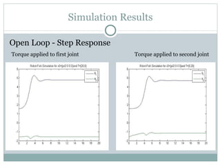
![Simulation Results x 0 = [-pi/2 -pi/2 ] x 0 = [pi/2 -pi/2 ]](https://image.slidesharecdn.com/projectpresentationnus-13211265575319-phpapp01-111112133808-phpapp01/85/Project-Presentation-Nus-33-320.jpg)
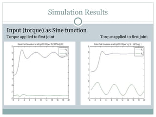
![Simulation Results x 0 = [pi/2 pi/2] x 0 = [-pi/2 pi/2 ]](https://image.slidesharecdn.com/projectpresentationnus-13211265575319-phpapp01-111112133808-phpapp01/85/Project-Presentation-Nus-34-320.jpg)
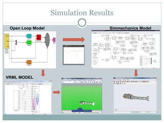
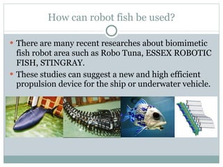
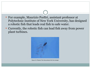

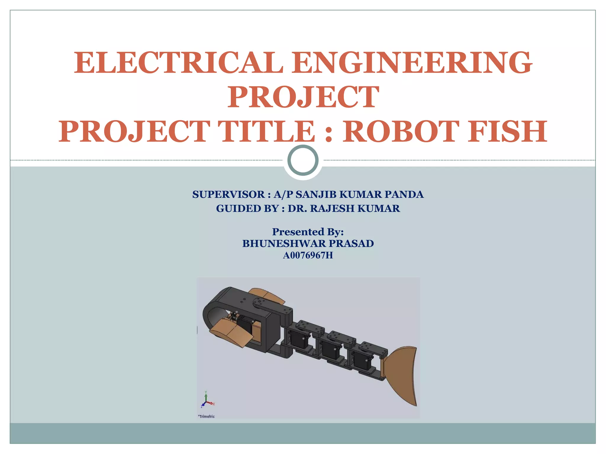
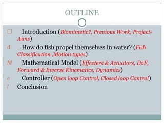
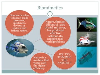
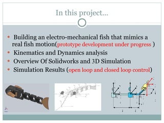
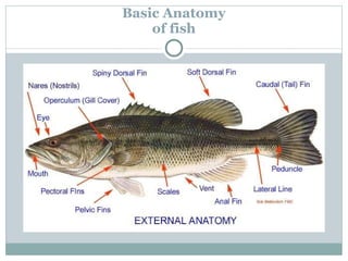
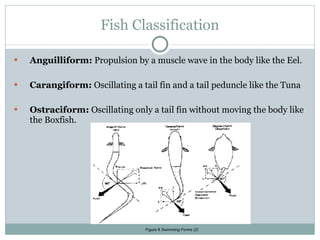
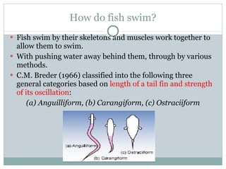
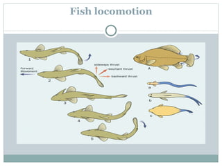
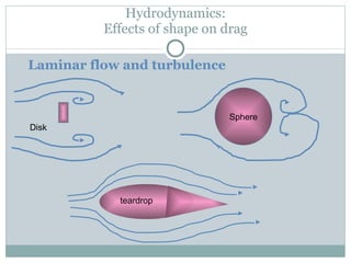
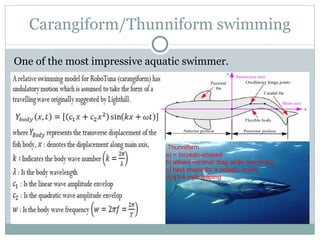
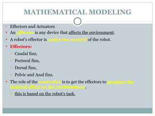
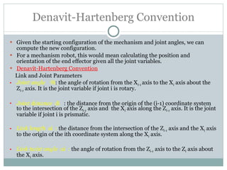
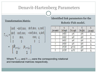
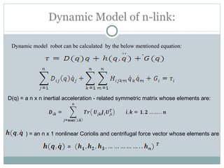
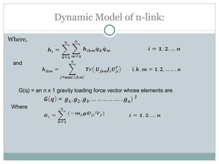
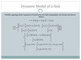
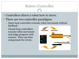
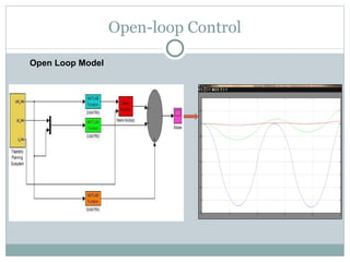
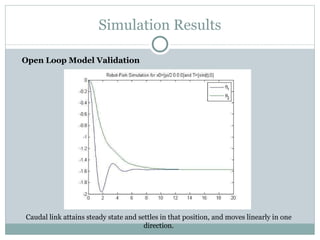
The document discusses the design of a robotic fish prototype. It covers the biomimetic inspiration of real fish motion, mathematical modeling including kinematics, dynamics, and degrees of freedom. Open and closed loop control strategies are examined through simulation. Potential applications of robotic fish include efficient ship propulsion and leading real fish to safety.


