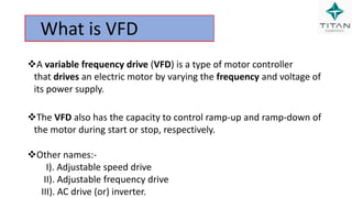
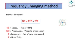
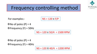
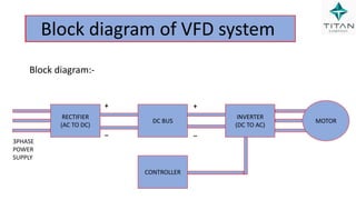
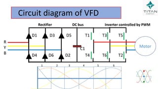
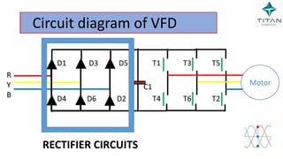
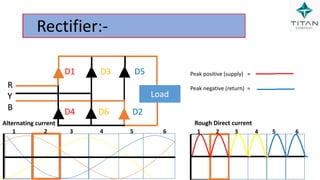
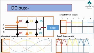
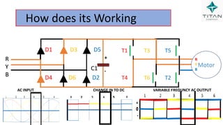
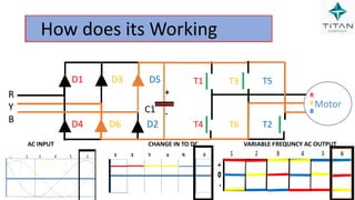
SlideShare a Scribd company logo
Prepared by :-
Thamizharasan k
VARIABLE FREQUENCY DRIVE
CONTENTS
1. What is Ac and Dc
2. Sine wave generation
3. What is Hz
4. What is Single phase and three phase.
5. What is starter and history
6. Type of starter
7. Explain each starter
8. What is VFD
9. Type of speed controlling method
10. Block diagram
11. Circuit diagram
12. Circuit diagram explanation
13. How its working
14. Application
15. Advantage and disadvantage
15. Troubleshoot in VFD.
16. What are the Communication in VFD.
17. Type of VFD.
18. Where is used VFD in our industry.
DURATION HRS :- 1.00 Hrs
Total Slide:-93
What is AC and DC
Alternating current
Direct current
What is Alternating current?
The current, which reverses its
direction periodically in second , is called
“Alternating Current”.
What is Direct current?
Direct current is the unidirectional
flow of an electric charge.
Sine wave generation
 A.C voltage may
be generated by rotating a coil in
a magnetic field or by rotating a
magnetic field within a stationary
coil. Induction.
 It says that whenever there is
a relative motion between the
conductor and the magnetic field
in which it is kept,an e.m.f gets
induced in the conductor
 The number of hertz (abbreviated Hz) equals the
number of cycles per second.
 Usually, the single phase voltage is 230V and the
frequency is 50Hz (depending on where you live).
What is Hz
Difference Between 1φ and 3φ Power Supplies
 Almost 90% of the electrical energy we use in our
day-to-day life is from alternating source like.
I) Our home appliances,
II)Office equipment
III)Industrial machines, etc..,
 Depending on the application, AC Power can be
delivered in either a Single Phase or a Three Phase
system.
Difference Between 1φ and 3φ Power Supplies
What is Single Phase Power Supply?
 As mentioned earlier, in a Single Phase Power
Supply, the power is distributed using only two
wires called Phase and neutral.
 Since AC Power takes the shape of a sinusoidal
wave, the voltage in a single phase supply peaks
at 900 during the positive cycle and again at
2700 during the negative cycle.
Difference Between 1φ and 3φ Power Supplies
.  The phase wire carries the current to
the load and the neutral wire
provides the return path of the
current.
 Since the voltage in a single phase
supply rises and falls, a constant
power cannot be delivered to the
load
Sine wave generation
What is three Phase Power Supply?
 A Three Phase Power Supply consists of three
power wires (or the three phases).
Additionally, depending on the type of the
circuit (which there are two types), you might
or might not have a neutral wire.
Sine wave generation
 In a three phase power supply system,
each AC Power Signal is 1200 out of phase
with each other. during one cycle of
3600,
This steady stream of power and ability to
handle higher loads makes a three phase
supply suitable for industrial commercial
operations.
What is Starter
 A Starter is a device that controls the use
of electrical power to equipment, usually a motor
 It is a switching device that consists of electrical
contacts
 As the name starters "start" motors. They can also
stop them, reverse them, and protect them.
 Contactors control the electric current to
the motor.
DOL Starter
Star Delta Starter
Auto Transformer starter
Soft Starter
VFD Starter
Type of Stater
Direct On Line Starter
 Direct on line starter (DOL) mainly used
small capacity motors (below 5 HP)
doesn’t have very high starting current,
such motors can withstand the starting
currents.
 There is no need to reduce the voltage to
the motor at start and hence motor can
be connected directly to the supply lines.
Star Delta starter
Star Delta starter
 A star delta starter is the most
commonly used method for the
starting of a 3 phase induction motor.
 When motor reaches about 80% of
its full load speed, it will begin to run
in a delta connected stator winding.
 A star delta starter is a type of
reduced voltage starter
Auto Transformer Starter
 Three-phase auto transformer is connected
in series with the motor. This transformer
reduces the voltage applied to the motor
and hence the current.
 This starter consists of changeover switch
that switches the motor between reduced
voltage and full voltage conditions. When
this switch is in the start position, a reduced
voltage is applied to the motor.
Soft Stater
Soft Stater
 In this method, semiconductor power
switches are employed for reducing the
starting current to the induction motor.
 It is another type of reduced voltage starter
and it connected in series with the line
voltage applied to the motor.
 This starter consists of back to back thyristors
or TRIACs in each phase of the stator winding
VFD Stater
What is VFD
A variable frequency drive (VFD) is a type of motor controller
that drives an electric motor by varying the frequency and voltage of
its power supply.
The VFD also has the capacity to control ramp-up and ramp-down of
the motor during start or stop, respectively.
Other names:-
I). Adjustable speed drive
II). Adjustable frequency drive
III). AC drive (or) inverter.
Speed controlling methods:
Change supply voltage
Changing rotor resistance
Change frequency
Frequency Changing method
Formula for speed:-
NS = 120 X F/P
NS = Speed. ( motor RPM)
120 = Phase Angle. (Phase to phase angle)
F = Frequency. (No of cycle per second)
P = No of Poles.
No of poles (P) = 4
Frequency (F) = 50Hz
NS = 120 X 50/4 = 1500 RPM
No of poles (P) = 4
Frequency (F) = 40Hz
NS = 120 X 40/4 = 1200 RPM
Frequency controlling method
For examples:- NS = 120 X F/P
Block diagram of VFD system
Block diagram:-
DC BUS
CONTROLLER
INVERTER
(DC TO AC)
RECTIFIER
(AC TO DC)
MOTOR
3PHASE
POWER
SUPPLY
+
_
+
_
How does its Working
D1 D3 D5 T1 T3 T5
C1
D4 D6 D2 T4 T6 T2
Circuit diagram of VFD
Motor
R
Y
B
1 2 3 4 5 6
Rectifier DC bus Inverter controlled by PWM
Components are :- Area:-
Diodes
Capacitor
 MOSFET or IGBT
Pulse width Modulations
What are the major components used
RECTIFIER
(AC TO DC)
DC BUS
INVERTER
(DC TO AC)
CONTROLLER
D1 D3 D5 T1 T3 T5
C1
D4 D6 D2 T4 T6 T2
Circuit diagram of VFD
Motor
R
Y
B
RECTIFIER CIRCUITS
Rectifier:-
Rectifier:-
 A diode is defined as a two-terminal
semiconductor device.
Anode (+)
Cathode(-)
 That only conducts current in one direction.
(so long as it is operated within a specified
voltage level).
Rectifier:-
Rectifier:-
Rectifier:-
 A bridge rectifier makes use of four
diodes in a bridge arrangement to
achieve full-wave rectification.
 The Red colour indicates that those
diodes are in forward bias and the
black colour indicates that those
diodes are in reverse bias
Rectifier:-
 The arrows shows the direction of
current flow.
 At a particular time any of the two
diodes will be Forward Biased and
the other two will be Reverse Biased,
Rectifier:-
R
Y
B
1 2 3 4 5 6
Load
D1 D3 D5
D4 D6 D2
Diode = D1 to D6
Load = Dc motor
R
Y
B
1 2 3 4 5 6
Load
R
Y
B
Alternating current
1 2 3 4 5 6
Rectifier:-
Peak positive (supply) =
Peak negative (return) =
Rough Direct current
D1 D3 D5
D4 D6 D2
R
Y
B
1 2 3 4 5 6
Load
R
Y
B
Alternating current
1 2 3 4 5 6
Rectifier:-
Peak positive (supply) =
Peak negative (return) =
Rough Direct current
D1 D3 D5
D4 D6 D2
R
Y
B
1 2 3 4 5 6
Load
R
Y
B
Alternating current
1 2 3 4 5 6
Rectifier:-
Peak positive (supply) =
Peak negative (return) =
Rough Direct current
D1 D3 D5
D4 D6 D2
R
Y
B
1 2 3 4 5 6
Load
R
Y
B
1 2 3 4 5 6
Rectifier:-
Alternating current
Peak positive (supply) =
Peak negative (return) =
Rough Direct current
D1 D3 D5
D4 D6 D2
R
Y
B
1 2 3 4 5 6
Load
R
Y
B
Alternating current
1 2 3 4 5 6
Rectifier:-
Peak positive (supply) =
Peak negative (return) =
Rough Direct current
D1 D3 D5
D4 D6 D2
R
Y
B
1 2 3 4 5 6
Load
R
Y
B
Alternating current
1 2 3 4 5 6
Rectifier:-
Peak positive (supply) =
Peak negative (return) =
Rough Direct current
D1 D3 D5
D4 D6 D2
D1 D3 D5 T1 T3 T5
C1
D4 D6 D2 T6 T4 T2
Circuit diagram of VFD
Motor
R
Y
B
DC BUS CIRCUIT
DC bus:-
DC bus:-
 DC bus is nothing but It capacitor
 Its function is to store the electrical energy and
give this energy again to the circuit when
necessary.
 In other words, it charges and discharges the
electric charge stored in it.
 It blocks the flow of DC and permits the flow of
AC.
DC bus:-
DC bus:-
R
Y
B
1 2 3 4 5 6
R
Y
B
Alternating current
1 2 3 4 5 6
Load
Rough Direct current
Smooth Direct current
1 2 3 4 5 6
D1 D3 D5
C1
D4 D6 D2
R
Y
B
1 2 3 4 5 6
R
Y
B
Alternating current
1 2 3 4 5 6
Load
Rough Direct current
Smooth Direct current
1 2 3 4 5 6
DC bus:-
D1 D3 D5
C1
D4 D6 D2
R
Y
B
1 2 3 4 5 6
R
Y
B
Alternating current
1 2 3 4 5 6
Load
Rough Direct current
Smooth Direct current
1 2 3 4 5 6
DC bus:-
D1 D3 D5
C1
D4 D6 D2
R
Y
B
1 2 3 4 5 6
R
Y
B
1 2 3 4 5 6
Load
Smooth Direct current
Rough Direct current
1 2 3 4 5 6
DC bus:-
Alternating current
D1 D3 D5
C1
D4 D6 D2
R
Y
B
1 2 3 4 5 6
R
Y
B
Alternating current
1 2 3 4 5 6
Load
Rough Direct current
Smooth Direct current
1 2 3 4 5 6
DC bus:-
D1 D3 D5
C1
D4 D6 D2
R
Y
B
1 2 3 4 5 6
Load
R
Y
B
Alternating current Rough Direct current
1 2 3 4 5 6
1 2 3 4 5 6
Smooth Direct current
DC bus:-
D1 D3 D5
C1
D4 D6 D2
Inverter
D1 D3 D5 T1 T3 T5
C1
D4 D6 D2 T6 T4 T2
Circuit diagram of VFD
Motor
R
Y
B
INVERTER CIRCUIT
Inverter
 Inverter converted Direct current to
Alternating current.
 Mainly using the components are:
 IGBT -----using in high capacity
application.
(OR)
 MOSFET---- using in Low capacity
application.
Inverter
 The MOSFET (Metal Oxide
Semiconductor Field Effect Transistor)
transistor is a semiconductor device.
 which is widely used for switching
and amplifying electronic signals in
the electronic devices.
 The MOSFET is a three terminal
device such as source, gate, and
drain.
Inverter
.
 An insulated-gate bipolar transistor
(IGBT) is a three-terminal power
semiconductor device.
 It is primarily used as an electronic
switch which, as it was developed,
came to combine high efficiency and
fast switching.
Inverter
 It is a solid state device (with no
moving parts).
 An IGBT works by applying voltage to
a semiconductor component,
therefore changing its properties to
block or create an electrical path.
 Much like an Solid State Relay but
built for higher power applications.
Inverter
 PWM – Pulse width modulation Digital
control is used to create a square wave,
a signal switched between on and off.
 The duration off "on time" is called
the pulse width.
 Inverter signal controlled by Pulse
width modulation
Inverter
 Duty cycle is the percentage of
the ratio of pulse duration,
or pulse width (PW) to the total period
(T) of the waveform.
Pulse Width Modulation (PWM)
Inverter
Motor
+
0
-
+
0
-
+
0
-
1 2 3 4 5 6
Output wave form
R
Y
B
+
-
IGBT OR MOSET = T1 TO T6
T1 T3 T5
T4 T6 T2
+
0
-
Alternating current Waveform
Inverter
Motor
+
0
-
+
0
-
+
0
-
+
0
-
1 2 3 4 5 6
Output wave form
R
Y
B
+
-
T1 T3 T5
T4 T6 T2
Inverter
Motor
+
0
-
+
0
-
+
0
-
+
0
-
1 2 3 4 5 6
Output wave form
R
Y
B
+
-
T1 T3 T5
T4 T6 T2
Inverter
Motor
+
0
-
+
0
-
+
0
-
+
0
-
1 2 3 4 5 6
Output wave form
R
Y
B
+
-
T1 T3 T5
T4 T6 T2
Inverter
Motor
+
0
-
+
0
-
+
0
-
+
0
-
1 2 3 4 5 6
Output wave form
R
Y
B
+
-
T1 T3 T5
T4 T6 T2
Inverter
Motor
+
0
-
+
0
-
+
0
-
+
0
-
1 2 3 4 5 6
Output wave form
R
Y
B
+
-
T1 T3 T5
T4 T6 T2
Inverter
Motor
+
0
-
+
0
-
+
0
-
+
0
-
1 2 3 4 5 6
Output wave form
R
Y
B
+
-
T1 T3 T5
T4 T6 T2
How does its Working
T1 T3 T5
T4 T6 T2
Motor
R
Y
B
+
-
R
Y
B
R
Y
B
D1 D3 D5
C1
D4 D6 D2
AC INPUT CHANGE IN TO DC VARIABLE FREQUNCY AC OUTPUT
How does its Working
R
Y
B
R
Y
B
Motor
R
Y
B
+
-
D1 D3 D5
C1
D4 D6 D2
T1 T3 T5
T4 T6 T2
AC INPUT CHANGE IN TO DC VARIABLE FREQUNCY AC OUTPUT
How does its Working
R
Y
B
R
Y
B
Motor
R
Y
B
+
-
D1 D3 D5
C1
D4 D6 D2
T1 T3 T5
T4 T6 T2
AC INPUT CHANGE IN TO DC VARIABLE FREQUNCY AC OUTPUT
How does its Working
R
Y
B
R
Y
B
Motor
R
Y
B
+
-
D1 D3 D5
C1
D4 D6 D2
T1 T3 T5
T4 T6 T2
AC INPUT CHANGE IN TO DC VARIABLE FREQUNCY AC OUTPUT
How does its Working
R
Y
B
R
Y
B
Motor
R
Y
B
+
-
D1 D3 D5
C1
D4 D6 D2
T1 T3 T5
T4 T6 T2
AC INPUT CHANGE IN TO DC VARIABLE FREQUNCY AC OUTPUT
How does its Working
R
Y
B
R
Y
B
Motor
R
Y
B
+
-
D1 D3 D5
C1
D4 D6 D2
T1 T3 T5
T4 T6 T2
AC INPUT CHANGE IN TO DC VARIABLE FREQUNCY AC OUTPUT
How does its Working
VFD Basic wiring connection
T1 T2 T3
L1 L2 L3
3POLE MCB
3PHASE INDUCTION
MOTOR
3 PHASE LINE
COM|FOR|REV|LOW|MID|HIG|
+VDC|REF|COM
Wiring Diagram
SPL - LOW SPEED
SPM - MEDIUM SPEED
SPH – HIGH SPEED
RST - RESTART
REV – REVERSE DIRECTION
FOR – FORWARD DIRECTION
ACM – COMMON
AI – CURRENT INPUT
VI –VOLTAGE INPUT
FA,FB,FC – REALAY OUTPUT
Some of the VFD Application
Cooling Tower
 Compressor
Blower
Boiler
Lathe work shops
Modern lift system
Pumping system etc..,
Advantage and Disadvantage of VFD
Advantage:-
 Smooth starting.
 Smooth acceleration & deceleration time.
 Zero RPM Achive.
 Stopping methods.
 Power saving
Disadvantage:-
 Cost is higher
 Skilled person required to change the parameter
Troubleshoot in VFD
Loose connections are among the most
common causes of faulty operation
in VFD applications. Just eyeballing a
connection is sometimes enough to know it's
loose.
VFD overload condition.
VFD overheat.
What are the communication
1. Delta VFD (MODBUS RS-485COMMUNICATION).
2. SIEMENS VFD(PROFI BUS COMMUNICATION).
3. ABB VFD (MODBUS COMMUNICATION).
4. Schneider (MODBUS COMMUNICATION) .
Where is used VFD in our industry
1. scrubber Schneider VFD 22kw 11kw
2. Cooling 150TR ABB VFD 5Kw
3. Secondary pump Vogon VFD 11Kw
4. Dust collector ABB VFD 4kw
Thank you ’’’’
’

More Related Content

Similar to VFD SYSTEM- Variable Frequency Drive applications

DC-DC power processing
DC-DC power processingDC-DC power processing
DC-DC power processing
Taimur Ijaz
 
nestraining-EE-EE Training Autom .ppt
nestraining-EE-EE Training Autom .pptnestraining-EE-EE Training Autom .ppt
nestraining-EE-EE Training Autom .ppt
pramodkommanaboina
 
Different type s of power converters fed relutance
Different type s of power converters fed relutanceDifferent type s of power converters fed relutance
Different type s of power converters fed relutance
Sambit Dash
 
Rectifiers (ac dc)
Rectifiers (ac dc) Rectifiers (ac dc)
Rectifiers (ac dc)
Taimur Ijaz
 
Ac dc converter
Ac  dc converterAc  dc converter
Ac dc converter
Tuvshinsanaa Baasanjav
 
3 phase current source inverter
3 phase  current  source  inverter3 phase  current  source  inverter
3 phase current source inverter
☆Engr.Mahamud Sajib Sajib
 
Synchmachine
SynchmachineSynchmachine
Synchmachine
Engineer Noman Shahid
 
Motor Control Relay, Pwm, DC and Stepper Motors
Motor Control Relay, Pwm, DC and Stepper MotorsMotor Control Relay, Pwm, DC and Stepper Motors
Motor Control Relay, Pwm, DC and Stepper Motors
Devashish Raval
 
Inverters (DC-AC)
Inverters (DC-AC)Inverters (DC-AC)
Inverters (DC-AC)
Taimur Ijaz
 
A survey on Single Phase to Three Phase Cyclo-Converter fed Induction Motor
A survey on Single Phase to Three Phase Cyclo-Converter fed Induction MotorA survey on Single Phase to Three Phase Cyclo-Converter fed Induction Motor
A survey on Single Phase to Three Phase Cyclo-Converter fed Induction Motor
IJSRD
 
electrical-actuation-systems.ppt
electrical-actuation-systems.pptelectrical-actuation-systems.ppt
electrical-actuation-systems.ppt
PiyushGupta632209
 
Half wave rectifier.pptx
Half wave rectifier.pptxHalf wave rectifier.pptx
Half wave rectifier.pptx
Docman6
 
DC Drives WITH DC DC (1).ppt
DC Drives WITH DC DC (1).pptDC Drives WITH DC DC (1).ppt
DC Drives WITH DC DC (1).ppt
VandyDp1
 
Multi Pulse Rectifier Using Different Phase Shifting Transformers and its THD...
Multi Pulse Rectifier Using Different Phase Shifting Transformers and its THD...Multi Pulse Rectifier Using Different Phase Shifting Transformers and its THD...
Multi Pulse Rectifier Using Different Phase Shifting Transformers and its THD...
IRJET Journal
 
Half- wave and Full-wave Rectifiers.pptx
Half- wave and Full-wave Rectifiers.pptxHalf- wave and Full-wave Rectifiers.pptx
Half- wave and Full-wave Rectifiers.pptx
suvadeepde
 
transformers.ppt
transformers.ppttransformers.ppt
transformers.ppt
jamla1
 
Full Wave Bridge Rectifier.pptx
Full Wave Bridge Rectifier.pptxFull Wave Bridge Rectifier.pptx
Full Wave Bridge Rectifier.pptx
RituSachan2
 
ANALYSIS OF FLYBACK CONVERTER
ANALYSIS OF FLYBACK CONVERTERANALYSIS OF FLYBACK CONVERTER
ANALYSIS OF FLYBACK CONVERTER
shiv kapil
 
Alternating Current Machines-Synchronous Machines
Alternating Current Machines-Synchronous MachinesAlternating Current Machines-Synchronous Machines
Alternating Current Machines-Synchronous Machines
Talia Carbis
 
3 _CRT Display Design_A_
3   _CRT Display Design_A_3   _CRT Display Design_A_
3 _CRT Display Design_A_
James Webb
 

Similar to VFD SYSTEM- Variable Frequency Drive applications (20)

DC-DC power processing
DC-DC power processingDC-DC power processing
DC-DC power processing
 
nestraining-EE-EE Training Autom .ppt
nestraining-EE-EE Training Autom .pptnestraining-EE-EE Training Autom .ppt
nestraining-EE-EE Training Autom .ppt
 
Different type s of power converters fed relutance
Different type s of power converters fed relutanceDifferent type s of power converters fed relutance
Different type s of power converters fed relutance
 
Rectifiers (ac dc)
Rectifiers (ac dc) Rectifiers (ac dc)
Rectifiers (ac dc)
 
Ac dc converter
Ac  dc converterAc  dc converter
Ac dc converter
 
3 phase current source inverter
3 phase  current  source  inverter3 phase  current  source  inverter
3 phase current source inverter
 
Synchmachine
SynchmachineSynchmachine
Synchmachine
 
Motor Control Relay, Pwm, DC and Stepper Motors
Motor Control Relay, Pwm, DC and Stepper MotorsMotor Control Relay, Pwm, DC and Stepper Motors
Motor Control Relay, Pwm, DC and Stepper Motors
 
Inverters (DC-AC)
Inverters (DC-AC)Inverters (DC-AC)
Inverters (DC-AC)
 
A survey on Single Phase to Three Phase Cyclo-Converter fed Induction Motor
A survey on Single Phase to Three Phase Cyclo-Converter fed Induction MotorA survey on Single Phase to Three Phase Cyclo-Converter fed Induction Motor
A survey on Single Phase to Three Phase Cyclo-Converter fed Induction Motor
 
electrical-actuation-systems.ppt
electrical-actuation-systems.pptelectrical-actuation-systems.ppt
electrical-actuation-systems.ppt
 
Half wave rectifier.pptx
Half wave rectifier.pptxHalf wave rectifier.pptx
Half wave rectifier.pptx
 
DC Drives WITH DC DC (1).ppt
DC Drives WITH DC DC (1).pptDC Drives WITH DC DC (1).ppt
DC Drives WITH DC DC (1).ppt
 
Multi Pulse Rectifier Using Different Phase Shifting Transformers and its THD...
Multi Pulse Rectifier Using Different Phase Shifting Transformers and its THD...Multi Pulse Rectifier Using Different Phase Shifting Transformers and its THD...
Multi Pulse Rectifier Using Different Phase Shifting Transformers and its THD...
 
Half- wave and Full-wave Rectifiers.pptx
Half- wave and Full-wave Rectifiers.pptxHalf- wave and Full-wave Rectifiers.pptx
Half- wave and Full-wave Rectifiers.pptx
 
transformers.ppt
transformers.ppttransformers.ppt
transformers.ppt
 
Full Wave Bridge Rectifier.pptx
Full Wave Bridge Rectifier.pptxFull Wave Bridge Rectifier.pptx
Full Wave Bridge Rectifier.pptx
 
ANALYSIS OF FLYBACK CONVERTER
ANALYSIS OF FLYBACK CONVERTERANALYSIS OF FLYBACK CONVERTER
ANALYSIS OF FLYBACK CONVERTER
 
Alternating Current Machines-Synchronous Machines
Alternating Current Machines-Synchronous MachinesAlternating Current Machines-Synchronous Machines
Alternating Current Machines-Synchronous Machines
 
3 _CRT Display Design_A_
3   _CRT Display Design_A_3   _CRT Display Design_A_
3 _CRT Display Design_A_
 

Recently uploaded

DEEP LEARNING FOR SMART GRID INTRUSION DETECTION: A HYBRID CNN-LSTM-BASED MODEL
DEEP LEARNING FOR SMART GRID INTRUSION DETECTION: A HYBRID CNN-LSTM-BASED MODELDEEP LEARNING FOR SMART GRID INTRUSION DETECTION: A HYBRID CNN-LSTM-BASED MODEL
DEEP LEARNING FOR SMART GRID INTRUSION DETECTION: A HYBRID CNN-LSTM-BASED MODEL
gerogepatton
 
Textile Chemical Processing and Dyeing.pdf
Textile Chemical Processing and Dyeing.pdfTextile Chemical Processing and Dyeing.pdf
Textile Chemical Processing and Dyeing.pdf
NazakatAliKhoso2
 
学校原版美国波士顿大学毕业证学历学位证书原版一模一样
学校原版美国波士顿大学毕业证学历学位证书原版一模一样学校原版美国波士顿大学毕业证学历学位证书原版一模一样
学校原版美国波士顿大学毕业证学历学位证书原版一模一样
171ticu
 
Computational Engineering IITH Presentation
Computational Engineering IITH PresentationComputational Engineering IITH Presentation
Computational Engineering IITH Presentation
co23btech11018
 
2008 BUILDING CONSTRUCTION Illustrated - Ching Chapter 02 The Building.pdf
2008 BUILDING CONSTRUCTION Illustrated - Ching Chapter 02 The Building.pdf2008 BUILDING CONSTRUCTION Illustrated - Ching Chapter 02 The Building.pdf
2008 BUILDING CONSTRUCTION Illustrated - Ching Chapter 02 The Building.pdf
Yasser Mahgoub
 
A SYSTEMATIC RISK ASSESSMENT APPROACH FOR SECURING THE SMART IRRIGATION SYSTEMS
A SYSTEMATIC RISK ASSESSMENT APPROACH FOR SECURING THE SMART IRRIGATION SYSTEMSA SYSTEMATIC RISK ASSESSMENT APPROACH FOR SECURING THE SMART IRRIGATION SYSTEMS
A SYSTEMATIC RISK ASSESSMENT APPROACH FOR SECURING THE SMART IRRIGATION SYSTEMS
IJNSA Journal
 
Engine Lubrication performance System.pdf
Engine Lubrication performance System.pdfEngine Lubrication performance System.pdf
Engine Lubrication performance System.pdf
mamamaam477
 
BPV-GUI-01-Guide-for-ASME-Review-Teams-(General)-10-10-2023.pdf
BPV-GUI-01-Guide-for-ASME-Review-Teams-(General)-10-10-2023.pdfBPV-GUI-01-Guide-for-ASME-Review-Teams-(General)-10-10-2023.pdf
BPV-GUI-01-Guide-for-ASME-Review-Teams-(General)-10-10-2023.pdf
MIGUELANGEL966976
 
CHINA’S GEO-ECONOMIC OUTREACH IN CENTRAL ASIAN COUNTRIES AND FUTURE PROSPECT
CHINA’S GEO-ECONOMIC OUTREACH IN CENTRAL ASIAN COUNTRIES AND FUTURE PROSPECTCHINA’S GEO-ECONOMIC OUTREACH IN CENTRAL ASIAN COUNTRIES AND FUTURE PROSPECT
CHINA’S GEO-ECONOMIC OUTREACH IN CENTRAL ASIAN COUNTRIES AND FUTURE PROSPECT
jpsjournal1
 
IEEE Aerospace and Electronic Systems Society as a Graduate Student Member
IEEE Aerospace and Electronic Systems Society as a Graduate Student MemberIEEE Aerospace and Electronic Systems Society as a Graduate Student Member
IEEE Aerospace and Electronic Systems Society as a Graduate Student Member
VICTOR MAESTRE RAMIREZ
 
Properties Railway Sleepers and Test.pptx
Properties Railway Sleepers and Test.pptxProperties Railway Sleepers and Test.pptx
Properties Railway Sleepers and Test.pptx
MDSABBIROJJAMANPAYEL
 
5214-1693458878915-Unit 6 2023 to 2024 academic year assignment (AutoRecovere...
5214-1693458878915-Unit 6 2023 to 2024 academic year assignment (AutoRecovere...5214-1693458878915-Unit 6 2023 to 2024 academic year assignment (AutoRecovere...
5214-1693458878915-Unit 6 2023 to 2024 academic year assignment (AutoRecovere...
ihlasbinance2003
 
Electric vehicle and photovoltaic advanced roles in enhancing the financial p...
Electric vehicle and photovoltaic advanced roles in enhancing the financial p...Electric vehicle and photovoltaic advanced roles in enhancing the financial p...
Electric vehicle and photovoltaic advanced roles in enhancing the financial p...
IJECEIAES
 
Advanced control scheme of doubly fed induction generator for wind turbine us...
Advanced control scheme of doubly fed induction generator for wind turbine us...Advanced control scheme of doubly fed induction generator for wind turbine us...
Advanced control scheme of doubly fed induction generator for wind turbine us...
IJECEIAES
 
22CYT12-Unit-V-E Waste and its Management.ppt
22CYT12-Unit-V-E Waste and its Management.ppt22CYT12-Unit-V-E Waste and its Management.ppt
22CYT12-Unit-V-E Waste and its Management.ppt
KrishnaveniKrishnara1
 
Recycled Concrete Aggregate in Construction Part III
Recycled Concrete Aggregate in Construction Part IIIRecycled Concrete Aggregate in Construction Part III
Recycled Concrete Aggregate in Construction Part III
Aditya Rajan Patra
 
Iron and Steel Technology Roadmap - Towards more sustainable steelmaking.pdf
Iron and Steel Technology Roadmap - Towards more sustainable steelmaking.pdfIron and Steel Technology Roadmap - Towards more sustainable steelmaking.pdf
Iron and Steel Technology Roadmap - Towards more sustainable steelmaking.pdf
RadiNasr
 
Understanding Inductive Bias in Machine Learning
Understanding Inductive Bias in Machine LearningUnderstanding Inductive Bias in Machine Learning
Understanding Inductive Bias in Machine Learning
SUTEJAS
 
Embedded machine learning-based road conditions and driving behavior monitoring
Embedded machine learning-based road conditions and driving behavior monitoringEmbedded machine learning-based road conditions and driving behavior monitoring
Embedded machine learning-based road conditions and driving behavior monitoring
IJECEIAES
 
Casting-Defect-inSlab continuous casting.pdf
Casting-Defect-inSlab continuous casting.pdfCasting-Defect-inSlab continuous casting.pdf
Casting-Defect-inSlab continuous casting.pdf
zubairahmad848137
 

Recently uploaded (20)

DEEP LEARNING FOR SMART GRID INTRUSION DETECTION: A HYBRID CNN-LSTM-BASED MODEL
DEEP LEARNING FOR SMART GRID INTRUSION DETECTION: A HYBRID CNN-LSTM-BASED MODELDEEP LEARNING FOR SMART GRID INTRUSION DETECTION: A HYBRID CNN-LSTM-BASED MODEL
DEEP LEARNING FOR SMART GRID INTRUSION DETECTION: A HYBRID CNN-LSTM-BASED MODEL
 
Textile Chemical Processing and Dyeing.pdf
Textile Chemical Processing and Dyeing.pdfTextile Chemical Processing and Dyeing.pdf
Textile Chemical Processing and Dyeing.pdf
 
学校原版美国波士顿大学毕业证学历学位证书原版一模一样
学校原版美国波士顿大学毕业证学历学位证书原版一模一样学校原版美国波士顿大学毕业证学历学位证书原版一模一样
学校原版美国波士顿大学毕业证学历学位证书原版一模一样
 
Computational Engineering IITH Presentation
Computational Engineering IITH PresentationComputational Engineering IITH Presentation
Computational Engineering IITH Presentation
 
2008 BUILDING CONSTRUCTION Illustrated - Ching Chapter 02 The Building.pdf
2008 BUILDING CONSTRUCTION Illustrated - Ching Chapter 02 The Building.pdf2008 BUILDING CONSTRUCTION Illustrated - Ching Chapter 02 The Building.pdf
2008 BUILDING CONSTRUCTION Illustrated - Ching Chapter 02 The Building.pdf
 
A SYSTEMATIC RISK ASSESSMENT APPROACH FOR SECURING THE SMART IRRIGATION SYSTEMS
A SYSTEMATIC RISK ASSESSMENT APPROACH FOR SECURING THE SMART IRRIGATION SYSTEMSA SYSTEMATIC RISK ASSESSMENT APPROACH FOR SECURING THE SMART IRRIGATION SYSTEMS
A SYSTEMATIC RISK ASSESSMENT APPROACH FOR SECURING THE SMART IRRIGATION SYSTEMS
 
Engine Lubrication performance System.pdf
Engine Lubrication performance System.pdfEngine Lubrication performance System.pdf
Engine Lubrication performance System.pdf
 
BPV-GUI-01-Guide-for-ASME-Review-Teams-(General)-10-10-2023.pdf
BPV-GUI-01-Guide-for-ASME-Review-Teams-(General)-10-10-2023.pdfBPV-GUI-01-Guide-for-ASME-Review-Teams-(General)-10-10-2023.pdf
BPV-GUI-01-Guide-for-ASME-Review-Teams-(General)-10-10-2023.pdf
 
CHINA’S GEO-ECONOMIC OUTREACH IN CENTRAL ASIAN COUNTRIES AND FUTURE PROSPECT
CHINA’S GEO-ECONOMIC OUTREACH IN CENTRAL ASIAN COUNTRIES AND FUTURE PROSPECTCHINA’S GEO-ECONOMIC OUTREACH IN CENTRAL ASIAN COUNTRIES AND FUTURE PROSPECT
CHINA’S GEO-ECONOMIC OUTREACH IN CENTRAL ASIAN COUNTRIES AND FUTURE PROSPECT
 
IEEE Aerospace and Electronic Systems Society as a Graduate Student Member
IEEE Aerospace and Electronic Systems Society as a Graduate Student MemberIEEE Aerospace and Electronic Systems Society as a Graduate Student Member
IEEE Aerospace and Electronic Systems Society as a Graduate Student Member
 
Properties Railway Sleepers and Test.pptx
Properties Railway Sleepers and Test.pptxProperties Railway Sleepers and Test.pptx
Properties Railway Sleepers and Test.pptx
 
5214-1693458878915-Unit 6 2023 to 2024 academic year assignment (AutoRecovere...
5214-1693458878915-Unit 6 2023 to 2024 academic year assignment (AutoRecovere...5214-1693458878915-Unit 6 2023 to 2024 academic year assignment (AutoRecovere...
5214-1693458878915-Unit 6 2023 to 2024 academic year assignment (AutoRecovere...
 
Electric vehicle and photovoltaic advanced roles in enhancing the financial p...
Electric vehicle and photovoltaic advanced roles in enhancing the financial p...Electric vehicle and photovoltaic advanced roles in enhancing the financial p...
Electric vehicle and photovoltaic advanced roles in enhancing the financial p...
 
Advanced control scheme of doubly fed induction generator for wind turbine us...
Advanced control scheme of doubly fed induction generator for wind turbine us...Advanced control scheme of doubly fed induction generator for wind turbine us...
Advanced control scheme of doubly fed induction generator for wind turbine us...
 
22CYT12-Unit-V-E Waste and its Management.ppt
22CYT12-Unit-V-E Waste and its Management.ppt22CYT12-Unit-V-E Waste and its Management.ppt
22CYT12-Unit-V-E Waste and its Management.ppt
 
Recycled Concrete Aggregate in Construction Part III
Recycled Concrete Aggregate in Construction Part IIIRecycled Concrete Aggregate in Construction Part III
Recycled Concrete Aggregate in Construction Part III
 
Iron and Steel Technology Roadmap - Towards more sustainable steelmaking.pdf
Iron and Steel Technology Roadmap - Towards more sustainable steelmaking.pdfIron and Steel Technology Roadmap - Towards more sustainable steelmaking.pdf
Iron and Steel Technology Roadmap - Towards more sustainable steelmaking.pdf
 
Understanding Inductive Bias in Machine Learning
Understanding Inductive Bias in Machine LearningUnderstanding Inductive Bias in Machine Learning
Understanding Inductive Bias in Machine Learning
 
Embedded machine learning-based road conditions and driving behavior monitoring
Embedded machine learning-based road conditions and driving behavior monitoringEmbedded machine learning-based road conditions and driving behavior monitoring
Embedded machine learning-based road conditions and driving behavior monitoring
 
Casting-Defect-inSlab continuous casting.pdf
Casting-Defect-inSlab continuous casting.pdfCasting-Defect-inSlab continuous casting.pdf
Casting-Defect-inSlab continuous casting.pdf
 

VFD SYSTEM- Variable Frequency Drive applications

  • 1. Prepared by :- Thamizharasan k VARIABLE FREQUENCY DRIVE
  • 2. CONTENTS 1. What is Ac and Dc 2. Sine wave generation 3. What is Hz 4. What is Single phase and three phase. 5. What is starter and history 6. Type of starter 7. Explain each starter 8. What is VFD 9. Type of speed controlling method 10. Block diagram 11. Circuit diagram 12. Circuit diagram explanation 13. How its working 14. Application 15. Advantage and disadvantage 15. Troubleshoot in VFD. 16. What are the Communication in VFD. 17. Type of VFD. 18. Where is used VFD in our industry. DURATION HRS :- 1.00 Hrs Total Slide:-93
  • 3. What is AC and DC Alternating current Direct current What is Alternating current? The current, which reverses its direction periodically in second , is called “Alternating Current”. What is Direct current? Direct current is the unidirectional flow of an electric charge.
  • 4. Sine wave generation  A.C voltage may be generated by rotating a coil in a magnetic field or by rotating a magnetic field within a stationary coil. Induction.  It says that whenever there is a relative motion between the conductor and the magnetic field in which it is kept,an e.m.f gets induced in the conductor
  • 5.  The number of hertz (abbreviated Hz) equals the number of cycles per second.  Usually, the single phase voltage is 230V and the frequency is 50Hz (depending on where you live). What is Hz
  • 6.
  • 7. Difference Between 1φ and 3φ Power Supplies  Almost 90% of the electrical energy we use in our day-to-day life is from alternating source like. I) Our home appliances, II)Office equipment III)Industrial machines, etc..,  Depending on the application, AC Power can be delivered in either a Single Phase or a Three Phase system.
  • 8. Difference Between 1φ and 3φ Power Supplies What is Single Phase Power Supply?  As mentioned earlier, in a Single Phase Power Supply, the power is distributed using only two wires called Phase and neutral.  Since AC Power takes the shape of a sinusoidal wave, the voltage in a single phase supply peaks at 900 during the positive cycle and again at 2700 during the negative cycle.
  • 9. Difference Between 1φ and 3φ Power Supplies .  The phase wire carries the current to the load and the neutral wire provides the return path of the current.  Since the voltage in a single phase supply rises and falls, a constant power cannot be delivered to the load
  • 10. Sine wave generation What is three Phase Power Supply?  A Three Phase Power Supply consists of three power wires (or the three phases). Additionally, depending on the type of the circuit (which there are two types), you might or might not have a neutral wire.
  • 11. Sine wave generation  In a three phase power supply system, each AC Power Signal is 1200 out of phase with each other. during one cycle of 3600, This steady stream of power and ability to handle higher loads makes a three phase supply suitable for industrial commercial operations.
  • 12. What is Starter  A Starter is a device that controls the use of electrical power to equipment, usually a motor  It is a switching device that consists of electrical contacts  As the name starters "start" motors. They can also stop them, reverse them, and protect them.  Contactors control the electric current to the motor.
  • 13.
  • 14. DOL Starter Star Delta Starter Auto Transformer starter Soft Starter VFD Starter Type of Stater
  • 15. Direct On Line Starter
  • 16. Direct On Line Starter  Direct on line starter (DOL) mainly used small capacity motors (below 5 HP) doesn’t have very high starting current, such motors can withstand the starting currents.  There is no need to reduce the voltage to the motor at start and hence motor can be connected directly to the supply lines.
  • 18. Star Delta starter  A star delta starter is the most commonly used method for the starting of a 3 phase induction motor.  When motor reaches about 80% of its full load speed, it will begin to run in a delta connected stator winding.  A star delta starter is a type of reduced voltage starter
  • 20. Auto Transformer Starter  Three-phase auto transformer is connected in series with the motor. This transformer reduces the voltage applied to the motor and hence the current.  This starter consists of changeover switch that switches the motor between reduced voltage and full voltage conditions. When this switch is in the start position, a reduced voltage is applied to the motor.
  • 22. Soft Stater  In this method, semiconductor power switches are employed for reducing the starting current to the induction motor.  It is another type of reduced voltage starter and it connected in series with the line voltage applied to the motor.  This starter consists of back to back thyristors or TRIACs in each phase of the stator winding
  • 24. What is VFD A variable frequency drive (VFD) is a type of motor controller that drives an electric motor by varying the frequency and voltage of its power supply. The VFD also has the capacity to control ramp-up and ramp-down of the motor during start or stop, respectively. Other names:- I). Adjustable speed drive II). Adjustable frequency drive III). AC drive (or) inverter.
  • 25. Speed controlling methods: Change supply voltage Changing rotor resistance Change frequency
  • 27. Frequency Changing method Formula for speed:- NS = 120 X F/P NS = Speed. ( motor RPM) 120 = Phase Angle. (Phase to phase angle) F = Frequency. (No of cycle per second) P = No of Poles.
  • 28. No of poles (P) = 4 Frequency (F) = 50Hz NS = 120 X 50/4 = 1500 RPM No of poles (P) = 4 Frequency (F) = 40Hz NS = 120 X 40/4 = 1200 RPM Frequency controlling method For examples:- NS = 120 X F/P
  • 29. Block diagram of VFD system Block diagram:- DC BUS CONTROLLER INVERTER (DC TO AC) RECTIFIER (AC TO DC) MOTOR 3PHASE POWER SUPPLY + _ + _
  • 30. How does its Working
  • 31. D1 D3 D5 T1 T3 T5 C1 D4 D6 D2 T4 T6 T2 Circuit diagram of VFD Motor R Y B 1 2 3 4 5 6 Rectifier DC bus Inverter controlled by PWM
  • 32. Components are :- Area:- Diodes Capacitor  MOSFET or IGBT Pulse width Modulations What are the major components used RECTIFIER (AC TO DC) DC BUS INVERTER (DC TO AC) CONTROLLER
  • 33. D1 D3 D5 T1 T3 T5 C1 D4 D6 D2 T4 T6 T2 Circuit diagram of VFD Motor R Y B RECTIFIER CIRCUITS
  • 35. Rectifier:-  A diode is defined as a two-terminal semiconductor device. Anode (+) Cathode(-)  That only conducts current in one direction. (so long as it is operated within a specified voltage level).
  • 38. Rectifier:-  A bridge rectifier makes use of four diodes in a bridge arrangement to achieve full-wave rectification.  The Red colour indicates that those diodes are in forward bias and the black colour indicates that those diodes are in reverse bias
  • 39. Rectifier:-  The arrows shows the direction of current flow.  At a particular time any of the two diodes will be Forward Biased and the other two will be Reverse Biased,
  • 40. Rectifier:- R Y B 1 2 3 4 5 6 Load D1 D3 D5 D4 D6 D2 Diode = D1 to D6 Load = Dc motor
  • 41. R Y B 1 2 3 4 5 6 Load R Y B Alternating current 1 2 3 4 5 6 Rectifier:- Peak positive (supply) = Peak negative (return) = Rough Direct current D1 D3 D5 D4 D6 D2
  • 42. R Y B 1 2 3 4 5 6 Load R Y B Alternating current 1 2 3 4 5 6 Rectifier:- Peak positive (supply) = Peak negative (return) = Rough Direct current D1 D3 D5 D4 D6 D2
  • 43. R Y B 1 2 3 4 5 6 Load R Y B Alternating current 1 2 3 4 5 6 Rectifier:- Peak positive (supply) = Peak negative (return) = Rough Direct current D1 D3 D5 D4 D6 D2
  • 44. R Y B 1 2 3 4 5 6 Load R Y B 1 2 3 4 5 6 Rectifier:- Alternating current Peak positive (supply) = Peak negative (return) = Rough Direct current D1 D3 D5 D4 D6 D2
  • 45. R Y B 1 2 3 4 5 6 Load R Y B Alternating current 1 2 3 4 5 6 Rectifier:- Peak positive (supply) = Peak negative (return) = Rough Direct current D1 D3 D5 D4 D6 D2
  • 46. R Y B 1 2 3 4 5 6 Load R Y B Alternating current 1 2 3 4 5 6 Rectifier:- Peak positive (supply) = Peak negative (return) = Rough Direct current D1 D3 D5 D4 D6 D2
  • 47.
  • 48. D1 D3 D5 T1 T3 T5 C1 D4 D6 D2 T6 T4 T2 Circuit diagram of VFD Motor R Y B DC BUS CIRCUIT
  • 50. DC bus:-  DC bus is nothing but It capacitor  Its function is to store the electrical energy and give this energy again to the circuit when necessary.  In other words, it charges and discharges the electric charge stored in it.  It blocks the flow of DC and permits the flow of AC.
  • 52. DC bus:- R Y B 1 2 3 4 5 6 R Y B Alternating current 1 2 3 4 5 6 Load Rough Direct current Smooth Direct current 1 2 3 4 5 6 D1 D3 D5 C1 D4 D6 D2
  • 53. R Y B 1 2 3 4 5 6 R Y B Alternating current 1 2 3 4 5 6 Load Rough Direct current Smooth Direct current 1 2 3 4 5 6 DC bus:- D1 D3 D5 C1 D4 D6 D2
  • 54. R Y B 1 2 3 4 5 6 R Y B Alternating current 1 2 3 4 5 6 Load Rough Direct current Smooth Direct current 1 2 3 4 5 6 DC bus:- D1 D3 D5 C1 D4 D6 D2
  • 55. R Y B 1 2 3 4 5 6 R Y B 1 2 3 4 5 6 Load Smooth Direct current Rough Direct current 1 2 3 4 5 6 DC bus:- Alternating current D1 D3 D5 C1 D4 D6 D2
  • 56. R Y B 1 2 3 4 5 6 R Y B Alternating current 1 2 3 4 5 6 Load Rough Direct current Smooth Direct current 1 2 3 4 5 6 DC bus:- D1 D3 D5 C1 D4 D6 D2
  • 57. R Y B 1 2 3 4 5 6 Load R Y B Alternating current Rough Direct current 1 2 3 4 5 6 1 2 3 4 5 6 Smooth Direct current DC bus:- D1 D3 D5 C1 D4 D6 D2
  • 58.
  • 60. D1 D3 D5 T1 T3 T5 C1 D4 D6 D2 T6 T4 T2 Circuit diagram of VFD Motor R Y B INVERTER CIRCUIT
  • 61. Inverter  Inverter converted Direct current to Alternating current.  Mainly using the components are:  IGBT -----using in high capacity application. (OR)  MOSFET---- using in Low capacity application.
  • 62. Inverter  The MOSFET (Metal Oxide Semiconductor Field Effect Transistor) transistor is a semiconductor device.  which is widely used for switching and amplifying electronic signals in the electronic devices.  The MOSFET is a three terminal device such as source, gate, and drain.
  • 63. Inverter .  An insulated-gate bipolar transistor (IGBT) is a three-terminal power semiconductor device.  It is primarily used as an electronic switch which, as it was developed, came to combine high efficiency and fast switching.
  • 64. Inverter  It is a solid state device (with no moving parts).  An IGBT works by applying voltage to a semiconductor component, therefore changing its properties to block or create an electrical path.  Much like an Solid State Relay but built for higher power applications.
  • 65. Inverter  PWM – Pulse width modulation Digital control is used to create a square wave, a signal switched between on and off.  The duration off "on time" is called the pulse width.  Inverter signal controlled by Pulse width modulation
  • 66. Inverter  Duty cycle is the percentage of the ratio of pulse duration, or pulse width (PW) to the total period (T) of the waveform.
  • 69. Inverter Motor + 0 - + 0 - + 0 - 1 2 3 4 5 6 Output wave form R Y B + - IGBT OR MOSET = T1 TO T6 T1 T3 T5 T4 T6 T2 + 0 - Alternating current Waveform
  • 70. Inverter Motor + 0 - + 0 - + 0 - + 0 - 1 2 3 4 5 6 Output wave form R Y B + - T1 T3 T5 T4 T6 T2
  • 71. Inverter Motor + 0 - + 0 - + 0 - + 0 - 1 2 3 4 5 6 Output wave form R Y B + - T1 T3 T5 T4 T6 T2
  • 72. Inverter Motor + 0 - + 0 - + 0 - + 0 - 1 2 3 4 5 6 Output wave form R Y B + - T1 T3 T5 T4 T6 T2
  • 73. Inverter Motor + 0 - + 0 - + 0 - + 0 - 1 2 3 4 5 6 Output wave form R Y B + - T1 T3 T5 T4 T6 T2
  • 74. Inverter Motor + 0 - + 0 - + 0 - + 0 - 1 2 3 4 5 6 Output wave form R Y B + - T1 T3 T5 T4 T6 T2
  • 75. Inverter Motor + 0 - + 0 - + 0 - + 0 - 1 2 3 4 5 6 Output wave form R Y B + - T1 T3 T5 T4 T6 T2
  • 76.
  • 77. How does its Working
  • 78. How does its Working T1 T3 T5 T4 T6 T2 Motor R Y B + - R Y B R Y B D1 D3 D5 C1 D4 D6 D2 AC INPUT CHANGE IN TO DC VARIABLE FREQUNCY AC OUTPUT
  • 79. How does its Working R Y B R Y B Motor R Y B + - D1 D3 D5 C1 D4 D6 D2 T1 T3 T5 T4 T6 T2 AC INPUT CHANGE IN TO DC VARIABLE FREQUNCY AC OUTPUT
  • 80. How does its Working R Y B R Y B Motor R Y B + - D1 D3 D5 C1 D4 D6 D2 T1 T3 T5 T4 T6 T2 AC INPUT CHANGE IN TO DC VARIABLE FREQUNCY AC OUTPUT
  • 81. How does its Working R Y B R Y B Motor R Y B + - D1 D3 D5 C1 D4 D6 D2 T1 T3 T5 T4 T6 T2 AC INPUT CHANGE IN TO DC VARIABLE FREQUNCY AC OUTPUT
  • 82. How does its Working R Y B R Y B Motor R Y B + - D1 D3 D5 C1 D4 D6 D2 T1 T3 T5 T4 T6 T2 AC INPUT CHANGE IN TO DC VARIABLE FREQUNCY AC OUTPUT
  • 83. How does its Working R Y B R Y B Motor R Y B + - D1 D3 D5 C1 D4 D6 D2 T1 T3 T5 T4 T6 T2 AC INPUT CHANGE IN TO DC VARIABLE FREQUNCY AC OUTPUT
  • 84.
  • 85. How does its Working
  • 86. VFD Basic wiring connection T1 T2 T3 L1 L2 L3 3POLE MCB 3PHASE INDUCTION MOTOR 3 PHASE LINE COM|FOR|REV|LOW|MID|HIG| +VDC|REF|COM
  • 87. Wiring Diagram SPL - LOW SPEED SPM - MEDIUM SPEED SPH – HIGH SPEED RST - RESTART REV – REVERSE DIRECTION FOR – FORWARD DIRECTION ACM – COMMON AI – CURRENT INPUT VI –VOLTAGE INPUT FA,FB,FC – REALAY OUTPUT
  • 88. Some of the VFD Application Cooling Tower  Compressor Blower Boiler Lathe work shops Modern lift system Pumping system etc..,
  • 89. Advantage and Disadvantage of VFD Advantage:-  Smooth starting.  Smooth acceleration & deceleration time.  Zero RPM Achive.  Stopping methods.  Power saving Disadvantage:-  Cost is higher  Skilled person required to change the parameter
  • 90. Troubleshoot in VFD Loose connections are among the most common causes of faulty operation in VFD applications. Just eyeballing a connection is sometimes enough to know it's loose. VFD overload condition. VFD overheat.
  • 91. What are the communication 1. Delta VFD (MODBUS RS-485COMMUNICATION). 2. SIEMENS VFD(PROFI BUS COMMUNICATION). 3. ABB VFD (MODBUS COMMUNICATION). 4. Schneider (MODBUS COMMUNICATION) .
  • 92. Where is used VFD in our industry 1. scrubber Schneider VFD 22kw 11kw 2. Cooling 150TR ABB VFD 5Kw 3. Secondary pump Vogon VFD 11Kw 4. Dust collector ABB VFD 4kw