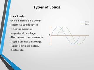
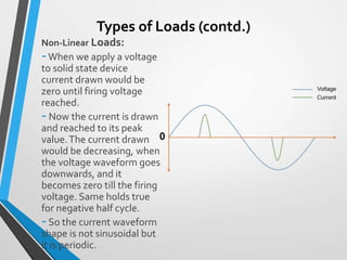
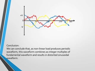
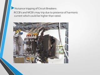
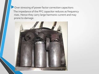
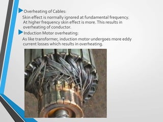
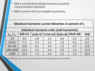
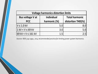
An Introduction to
Power System
Harmonics
Prepared by
Krunal ShahSubodhTech
Learning Objective
At the end of seminar we can be able to:
Increased awareness of Harmonics and its effect.
Interpretation of definition of harmonics.
Know how harmonics are generated.
Know adverse effects of harmonics in electrical system.
Interpreting IEEE 519-1992, 2014 tables for limiting
Harmonics in Power system.
Benefits of Seminar
Understanding and awareness related to harmonics
would increase.
Clarity on harmonics would help engineers to find
root cause of failures of equipments.
Maintenance engineers can take corrective actions
in context with harmonics.
Content
What is Fundamental Frequency?
Definition of Harmonics
Origin of Harmonics
Effects of harmonics
IEEE 519-1992, 2014
What is Frequency?
So 50hz frequency means, 50 cycles completed in 1
sec.
+
-
+
Time
One Cycle
Definition of Harmonics
Definition
 Fourier theory tells us that any repetitive waveform can be
defined in terms of summing sinusoidal waveforms which
are integer multiples (or harmonics) of the fundamental
frequency.
 The harmonic with frequency corresponding to the period
of the original waveform is called fundamental and the
harmonic with frequency equal to “n” times that of the
fundamental is called harmonic component of order “n”.
To Summarize: the harmonics are nothing less than the
components of a distorted waveform and their use allows us
to analyse any periodic non-sinusoidal waveform through
different sinusoidal waveform components.
Origin of Harmonics
Linear Loads:
-A linear element in a power
system is a component in
which the current is
proportional to voltage.
-This means current waveform
shape is same as the voltage.
Typical example is motors,
heaters etc.
Types of Loads
Types of Loads (contd.)
Non-Linear Loads:
-When we apply a voltage
to solid state device
current drawn would be
zero until firing voltage
reached.
-Now the current is drawn
and reached to its peak
value.The current drawn
would be decreasing, when
the voltage waveform goes
downwards, and it
becomes zero till the firing
voltage. Same holds true
for negative half cycle.
-So the current waveform
shape is not sinusoidal but
it is periodic.
Conclusion:
We can conclude that, as non-linear load produces periodic
waveform, this waveform combines as integer multiples of
fundamental waveform and results in distorted sinusoidal
waveform.
Devices producing harmonics
SMPS (in Personal Computers)
UPS (single and three phase)
VFD’s
Welding machines having rectifier
What Harmonics are not?
• Dips
• ImpulsiveTransient (very short rise and
decay time)
e.g. lightening strike, ESD, poor grounding,
stray capacitance etc.
• OscillatoryTransient (decays within an electric
cycle)
e.g. abruptly on or off of inductive motors,
switching on or off of power factor
capacitors.
Effects of Harmonics
Engineering Perspective:
Neutral conductor overheating:
When the balance load distribution is not there then
the current also flows from neutral and neutral gets
overheated.
Also when harmonics are present in power system
then also the neutral may get overheated.
Effects onTransformer:
The transformer eddy current losses increases with
square of harmonics number.This results in heating
of transformer.
Nuisance tripping of Circuit Breakers:
RCCB’s and MCB’s may trip due to presence of harmonic
current which could be higher than rated.
Over stressing of power factor correction capacitors:
The impedance of the PFC capacitor reduces as frequency
rises. Hence they carry large harmonic current and may
prone to damage.
Overheating of Cables:
Skin effect is normally ignored at fundamental frequency.
At higher frequency skin effect is more.This results in
overheating of conductor.
Induction Motor overheating:
As like transformer, induction motor undergoes more eddy
current losses which results in overheating.
Voltage drops may occur due to harmonics.
Causing EMI to sensitive signals.
Business Perspective
• Increased maintenance and replacement cost.
• Interruptions and downtimes cost.
• Reduced system capacity and thus increaseCAPEX by
unnecessary expansion.
IEEE 519-1992,2014
• IEEE is worried aboutVoltage harmonics caused by
current waveform distortion.
• IEEE is concern with your neighboring factories.
ISC / IL 3≤h<11 11≤h<17 17≤h<23 23≤h<35 35≤h<50 TDD
<20 4.0 2.0 1.5 0.6 0.3 5.0
20<50 7.0 3.5 2.5 1.0 0.5 8.0
50<100 10.0 4.5 4.0 1.5 0.7 12.0
100<1000 12.0 5.5 5.0 2.0 1.0 15.0
>1000 15.0 7.0 6.0 2.5 1.4 20.0
Maximum harmonic current distortion in percent of IL
Individual harmonic order (odd harmonics)
Source: IEEE 519-1992, 2014 recommended practice for limiting power system harmonics.
V ≤ 1.0 kV 5.0 8.0
1 kV < V ≤ 69 kV 3.0 5.0
69 kV < V ≤ 161 kV 1.5 2.5
Bus voltage V at
PCC
Individual
harmonic (%)
Total harmonic
distortion THD(%)
Voltage harmonics distortion limits
Source: IEEE 519-1992, 2014 recommended practice for limiting power system harmonics.
Want to learnmore about harmonics current?
Take our online course on UDEMY
Copy the below link
https://www.udemy.com/course/learn-about-power-system-harmonics-
from-scratch/?referralCode=97F1167DEB29FBB994FF
Life time access
Get an ebook of Power System
Harmonics (a quick reference guide) onAmazon
in just $1.11 Copy the below link
https://www.amazon.in/Power-System-Harmonics-Its-Mitigation-
ebook/dp/B076GRXPV2/ref=sr_1_16?keywords=power+system+harmonics&
qid=1581957699&sr=8-16
: Subodh Tech Training
: www.engineershub.co.in
Thank You

An introduction to power system harmonics

  • 1.
    An Introduction to PowerSystem Harmonics Prepared by Krunal ShahSubodhTech
  • 2.
    Learning Objective At theend of seminar we can be able to: Increased awareness of Harmonics and its effect. Interpretation of definition of harmonics. Know how harmonics are generated. Know adverse effects of harmonics in electrical system. Interpreting IEEE 519-1992, 2014 tables for limiting Harmonics in Power system.
  • 3.
    Benefits of Seminar Understandingand awareness related to harmonics would increase. Clarity on harmonics would help engineers to find root cause of failures of equipments. Maintenance engineers can take corrective actions in context with harmonics.
  • 4.
    Content What is FundamentalFrequency? Definition of Harmonics Origin of Harmonics Effects of harmonics IEEE 519-1992, 2014
  • 5.
    What is Frequency? So50hz frequency means, 50 cycles completed in 1 sec. + - + Time One Cycle
  • 6.
  • 7.
    Definition  Fourier theorytells us that any repetitive waveform can be defined in terms of summing sinusoidal waveforms which are integer multiples (or harmonics) of the fundamental frequency.  The harmonic with frequency corresponding to the period of the original waveform is called fundamental and the harmonic with frequency equal to “n” times that of the fundamental is called harmonic component of order “n”. To Summarize: the harmonics are nothing less than the components of a distorted waveform and their use allows us to analyse any periodic non-sinusoidal waveform through different sinusoidal waveform components.
  • 10.
  • 11.
    Linear Loads: -A linearelement in a power system is a component in which the current is proportional to voltage. -This means current waveform shape is same as the voltage. Typical example is motors, heaters etc. Types of Loads
  • 12.
    Types of Loads(contd.) Non-Linear Loads: -When we apply a voltage to solid state device current drawn would be zero until firing voltage reached. -Now the current is drawn and reached to its peak value.The current drawn would be decreasing, when the voltage waveform goes downwards, and it becomes zero till the firing voltage. Same holds true for negative half cycle. -So the current waveform shape is not sinusoidal but it is periodic.
  • 13.
    Conclusion: We can concludethat, as non-linear load produces periodic waveform, this waveform combines as integer multiples of fundamental waveform and results in distorted sinusoidal waveform.
  • 14.
    Devices producing harmonics SMPS(in Personal Computers) UPS (single and three phase) VFD’s Welding machines having rectifier
  • 15.
    What Harmonics arenot? • Dips • ImpulsiveTransient (very short rise and decay time) e.g. lightening strike, ESD, poor grounding, stray capacitance etc. • OscillatoryTransient (decays within an electric cycle) e.g. abruptly on or off of inductive motors, switching on or off of power factor capacitors.
  • 16.
  • 17.
    Engineering Perspective: Neutral conductoroverheating: When the balance load distribution is not there then the current also flows from neutral and neutral gets overheated. Also when harmonics are present in power system then also the neutral may get overheated. Effects onTransformer: The transformer eddy current losses increases with square of harmonics number.This results in heating of transformer.
  • 18.
    Nuisance tripping ofCircuit Breakers: RCCB’s and MCB’s may trip due to presence of harmonic current which could be higher than rated.
  • 19.
    Over stressing ofpower factor correction capacitors: The impedance of the PFC capacitor reduces as frequency rises. Hence they carry large harmonic current and may prone to damage.
  • 20.
    Overheating of Cables: Skineffect is normally ignored at fundamental frequency. At higher frequency skin effect is more.This results in overheating of conductor. Induction Motor overheating: As like transformer, induction motor undergoes more eddy current losses which results in overheating.
  • 21.
    Voltage drops mayoccur due to harmonics. Causing EMI to sensitive signals. Business Perspective • Increased maintenance and replacement cost. • Interruptions and downtimes cost. • Reduced system capacity and thus increaseCAPEX by unnecessary expansion.
  • 22.
  • 23.
    • IEEE isworried aboutVoltage harmonics caused by current waveform distortion. • IEEE is concern with your neighboring factories. ISC / IL 3≤h<11 11≤h<17 17≤h<23 23≤h<35 35≤h<50 TDD <20 4.0 2.0 1.5 0.6 0.3 5.0 20<50 7.0 3.5 2.5 1.0 0.5 8.0 50<100 10.0 4.5 4.0 1.5 0.7 12.0 100<1000 12.0 5.5 5.0 2.0 1.0 15.0 >1000 15.0 7.0 6.0 2.5 1.4 20.0 Maximum harmonic current distortion in percent of IL Individual harmonic order (odd harmonics) Source: IEEE 519-1992, 2014 recommended practice for limiting power system harmonics.
  • 24.
    V ≤ 1.0kV 5.0 8.0 1 kV < V ≤ 69 kV 3.0 5.0 69 kV < V ≤ 161 kV 1.5 2.5 Bus voltage V at PCC Individual harmonic (%) Total harmonic distortion THD(%) Voltage harmonics distortion limits Source: IEEE 519-1992, 2014 recommended practice for limiting power system harmonics.
  • 25.
    Want to learnmoreabout harmonics current? Take our online course on UDEMY Copy the below link https://www.udemy.com/course/learn-about-power-system-harmonics- from-scratch/?referralCode=97F1167DEB29FBB994FF Life time access Get an ebook of Power System Harmonics (a quick reference guide) onAmazon in just $1.11 Copy the below link https://www.amazon.in/Power-System-Harmonics-Its-Mitigation- ebook/dp/B076GRXPV2/ref=sr_1_16?keywords=power+system+harmonics& qid=1581957699&sr=8-16
  • 26.
    : Subodh TechTraining : www.engineershub.co.in
  • 27.