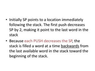
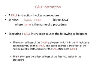
Chap 8 The stack and introduction to procedures & Chapter 9 multiplication an...warda aziz
this pdf covers solution to chapter 8 and 9 of assembly language and organization of the IBM PC. if you find any mistakes in my writing , please disccuss with me.
Introduction to ibm pc assembly languagewarda aziz
The Solution manual of COAL
Chapter NO 4. exercise
if anyone has Questions Regarding this exercise.
contact me on my given Email-ID.
i will guide you. Thank you!
Chapter 5The proessor status and the FLAGS registerswarda aziz
solution manual to COMPUTER ORGANIZATION AND ASSEMBLY LANGUAGE CHAPTER 5.
If you find any mistake in the manual please share with me ... it will be appreciated
Organization of the ibm personal computerswarda aziz
The Solution manual of COAL
Chapter NO 3. exercise
if anyone has Questions Regarding this exercise.
contact me on my given Email-ID.
i will guide you. Thank you!
chapter 7 Logic, shift and rotate instructionswarda aziz
this is a solution to exercise of chapter 7 from Assembly language programming and organization of the IBM PC.
If you find any mistakes in my solution , please discuss with me. as i am also a human and can do mistakes.
Assembly Language Programming and Organization of the IBM PC
By Yu and Marut
Solution Manual
( Ch.1 to ch.10 )
Written by :
Eng. Amer Mohammed Al-khsabah
For Online Tutorial :
http://sh.st/QaM4Z
INC and DEC Instructions
ADD Instruction
SUB Instruction
NEG Instruction
Implementing Arithmetic Expressions
Flags Affected by Addition and Subtraction
Example Program (AddSub3)
A microprocessor is an electronic component that is used by a computer to do its work. It is a central processing unit on a single integrated circuit chip containing millions of very small components including transistors, resistors, and diodes that work together.
IoT Based Smart Energy Meter using Raspberry Pi and Arduino Bilal Amjad
This project, design and implemented a low-cost IoT based energy monitoring system (smart energy meter) for real-time monitoring of all electrical parameters i.e. AC voltage, AC current, active power, total energy consumption, power factor, frequency, and tariff. The design is based on a low-cost PZEM-004T, using a non-invasive Current Transformer
(CT) sensors, Arduino and Raspberry pi. Electrical measurements are done by PZEM-004T and CT sensors through Arduino. Raspberry pi communicates with Arduino through serial communication to retrieve these sensor’s data and send it to the server via internet. As a result, the developed energy monitoring system can successfully record the voltage, current, active power, power factor, frequency, accumulative power consumption and tariff. Consumers will be able to
see their electricity usage and the tariff according to the energy usage in real-time through web and mobile application. In case of any fault e.g., short circuit or power supply cut off, the consumer will receive a text message on his mobile number. Moreover, consumers will be able to receive the tariff on a weekly or monthly basis.
Power Systems analysis with MATPOWER and Simscape Electrical (MATLAB/Simulink) Bilal Amjad
The report analyses the power flow studies done in MATPOWER, some three-phase circuits and the operation of the DFIG wind turbine using Simcape Electrical library in Simulink.
The work was submitted to the University of Bradford as a part of the coursework during my MSc program.
Solar Radiation monthly prediction and forecasting using Machine Learning tec...Bilal Amjad
The whole world is trying to reduce the CO2 emission by using renewable energy resources
(RERs) instead of fossil fuels especially for electricity generation. One of the main RERs for
electricity is the sun. Soler panels are used are used for capturing the energy of the sun using photovoltaic
(PV) cells. The output of PV’s depends on the weather and climate.
So, it is very important to know how much energy can be harvested in upcoming years or months
by predicting the solar energy for a particular area of earth, using historical data. In this work, two
machine learning techniques are used to forecast solar radiation using historical data. This will
help the energy companies in planning and designing of long-term goals for sustainable electricity
generation.
A presentation on "Big Data in Smart Grid" by MSc students at the University of Bradford, submitted as a part of coursework. It addresses the challenges, opportunities and issues related to Big Data and Data Protection in Smart Grid.
Flexibility of Power System (Sources of flexibility & flexibility markets)Bilal Amjad
This presentation gives a detail explanation of power system flexibility, flexibility in traditional power system, future flexibility needs and resources and flexibility markets.
Forklift Classes Overview by Intella PartsIntella Parts
Discover the different forklift classes and their specific applications. Learn how to choose the right forklift for your needs to ensure safety, efficiency, and compliance in your operations.
For more technical information, visit our website https://intellaparts.com
Water scarcity is the lack of fresh water resources to meet the standard water demand. There are two type of water scarcity. One is physical. The other is economic water scarcity.
Welcome to WIPAC Monthly the magazine brought to you by the LinkedIn Group Water Industry Process Automation & Control.
In this month's edition, along with this month's industry news to celebrate the 13 years since the group was created we have articles including
A case study of the used of Advanced Process Control at the Wastewater Treatment works at Lleida in Spain
A look back on an article on smart wastewater networks in order to see how the industry has measured up in the interim around the adoption of Digital Transformation in the Water Industry.
TECHNICAL TRAINING MANUAL GENERAL FAMILIARIZATION COURSEDuvanRamosGarzon1
AIRCRAFT GENERAL
The Single Aisle is the most advanced family aircraft in service today, with fly-by-wire flight controls.
The A318, A319, A320 and A321 are twin-engine subsonic medium range aircraft.
The family offers a choice of engines
Hybrid optimization of pumped hydro system and solar- Engr. Abdul-Azeez.pdffxintegritypublishin
Advancements in technology unveil a myriad of electrical and electronic breakthroughs geared towards efficiently harnessing limited resources to meet human energy demands. The optimization of hybrid solar PV panels and pumped hydro energy supply systems plays a pivotal role in utilizing natural resources effectively. This initiative not only benefits humanity but also fosters environmental sustainability. The study investigated the design optimization of these hybrid systems, focusing on understanding solar radiation patterns, identifying geographical influences on solar radiation, formulating a mathematical model for system optimization, and determining the optimal configuration of PV panels and pumped hydro storage. Through a comparative analysis approach and eight weeks of data collection, the study addressed key research questions related to solar radiation patterns and optimal system design. The findings highlighted regions with heightened solar radiation levels, showcasing substantial potential for power generation and emphasizing the system's efficiency. Optimizing system design significantly boosted power generation, promoted renewable energy utilization, and enhanced energy storage capacity. The study underscored the benefits of optimizing hybrid solar PV panels and pumped hydro energy supply systems for sustainable energy usage. Optimizing the design of solar PV panels and pumped hydro energy supply systems as examined across diverse climatic conditions in a developing country, not only enhances power generation but also improves the integration of renewable energy sources and boosts energy storage capacities, particularly beneficial for less economically prosperous regions. Additionally, the study provides valuable insights for advancing energy research in economically viable areas. Recommendations included conducting site-specific assessments, utilizing advanced modeling tools, implementing regular maintenance protocols, and enhancing communication among system components.
Quality defects in TMT Bars, Possible causes and Potential Solutions.PrashantGoswami42
Maintaining high-quality standards in the production of TMT bars is crucial for ensuring structural integrity in construction. Addressing common defects through careful monitoring, standardized processes, and advanced technology can significantly improve the quality of TMT bars. Continuous training and adherence to quality control measures will also play a pivotal role in minimizing these defects.
3. The Stack
• The stack segment of a program is used for temporary
storage of data and addresses
• A stack is a one-dimensional data structure
• Items are added to and removed from one end of the
structure using a "Last In - First Out" technique (LIFO)
• The top of the stack is the last addition to the stack
• The statement .STACK 100H in your program sets
aside a block of 256 bytes of memory to hold the stack
• The SS (Stack Segment Register) contains the segment
number of the stack segment
4. The Stack (cont’d)
• The complete segment:offset address to access the stack
is SS:SP
• Initially before any data or addresses have been placed on
the stack, the SP contains the offset address of the
memory location immediately following the stack segment
6. PUSH Instruction
• PUSH instruction adds a new word to the stack
• SYNTAX: PUSH source
where source is a 16-bit register or memory
word
• PUSH instruction causes
– the stack pointer (SP) to be decreased by 2.
– Then a copy of the value in the source field is placed in
the address specified by SS:SP.
7. • Initially SP points to a location immediately
following the stack. The first push decreases
SP by 2, making it point to the last word in the
stack
• Because each PUSH decreases the SP, the
stack is filled a word at a time backwards from
the last available word in the stack toward the
beginning of the stack.
8. How Words Are Added To Stack
Offset
0000
00F4
00F6
00F8
00FA
00FC
00FE
0100
It stack is empty, SP has a value of
100h; otherwise it has a value
between 0000-00FEh
SP:
(Beyond the end of the stack)
SP
9. How Words Are Added To Stack
Offset
0000
00F4
00F6
00F8
00FA
00FC
00FE
0100
0100SP:
(Beyond the end of the stack)
SP
1234AX:
5678BX:
10. How Words Are Added To Stack
Offset
0000
00F4
00F6
00F8
00FA
00FC
00FE
0100
00FESP:
(Beyond the end of the stack)
SP
1234AX:
5678BX:
1234
11. How Words Are Added To Stack
Offset
0000
00F4
00F6
00F8
00FA
00FC
00FE
0100
(Beyond the end of the stack)
SP
1234AX:
5678BX: 5678
1234
00FCSP:
12. POP Instruction
• POP instruction removes the last word placed on the stack
• SYNTAX: POP destination
– where source is a 16-bit register or memory word
• POP instruction causes
– the contents of SS:SP to be moved to the destination field
– It increases the stack pointer (SP) by 2
• Restrictions:
1.PUSH and POP work only with words
2.Byte and immediate data operands are illegal
13. How Words Are Added To Stack
Offset
0000
00F4
00F6
00F8
00FA
00FC
00FE
0100
(Beyond the end of the stack)
SP
FFFFCX:
0001DX:
5678
1234
00FCSP:
14. How Words Are Added To Stack
Offset
0000
00F4
00F6
00F8
00FA
00FC
00FE
0100
(Beyond the end of the stack)
SP
FFFFCX:
0001DX:
5678
1234
00FESP:
5678
15. How Words Are Added To Stack
Offset
0000
00F4
00F6
00F8
00FA
00FC
00FE
0100
(Beyond the end of the stack)
SP
FFFFCX:
0001DX:
5678
1234
0100SP:
5678
1234
16. FLAGS Register and Stack
• PUSHF
– pushes (copies) the contents of the FLAGS register onto
the stack. It has no operands
• POPF
– pops (copies) the contents of the top word in the stack to
the FLAGS register. It has no operands
• NOTES:
– PUSH, POP, and PUSHF do not affect the flags !!
– POPF could theoretically change all the flags because it resets the
FLAGS REGISTER to some original value that you have previously saved
with the PUSHF instruction
17. Example: Fill up the trace table given below.
Instructions AX
MOV AX,843AH
BX CX SI SP Stack Data Address Data
0100
0101
0102
0103
0104
0105
0106
0107
0108
0109
010A
010B
010C
010D
010E
3F
78
5A
C8
93
59
4F
A3
7E
F4
09
8A
5C
6A
45
INC AX
PUSH AX
MOV BX, 2354H
MOV BL,AL
POP AX
PUSH BX
MOV SI,0104H
PUSH [010A]
POP DX
POP AX
PUSH [SI+4]
INC AL
POP AX
INC AX
19. Important Notes
• Not only can the programmer use the stack but DOS can
and also does use the stack
• In fact DOS uses the stack every time the user executes an
INT 21h function
• Because of the "last-in first-out" nature of the stack, the
order that items are removed from the stack is the reverse
of the order in which they are placed on the stack
20. Example Program
• The following code allows a user to input a string
consisting of 10 characters and then displays the 10
characters in reverse order on the screen
TITLE DISPLAY THE 10 CHARACTERS IN REVERSE ORDER
.MODEL SMALL
.STACK 100H
.DATA
CR EQU 0DH
LF EQU 0AH
MESSAGE DB CR,LF,'PLEASE TYPE ANY 10 '
DB ' CHARACTERS',CR,LF,'$'
REVERSE DB CR,LF,'THE CHARACTERS IN REVERSE'
DB ' ARE:',CR,LF,'$'
22. READ:
INT 21H
PUSH AX ;CAN'T PUSH AL SO PUSH AX!
LOOP READ
;-----------------------------PRINT REVERSE MESSAGE
MOV AH,9
LEA DX,REVERSE
INT 21H
;-----------------------------PREPARE TO PRINT IN REVERSE
MOV CX,10
MOV AH,2
Example
Program
(cont’d)
23. DISP:
POP DX
INT 21H
LOOP DISP
;-----------------------------RETURN TO DOS
MOV DL,CR
INT 21h
MOV DL,LF
INT 21h
MOV AH,4CH
INT 21H
MAIN ENDP
END MAIN
Example
Program
(cont’d)
24. Terminology of Procedures
• Top-down program design
– Decompose the original problem into a series of
subproblems that are easier to solve than the original
problem
• Subproblems in assembler language can be structured as a
collection of procedures
• Main procedure contains the entry point to the program
and can call one of the other procedures using a CALL
statement
• It is possible for a called sub-procedure to call other
procedures
• In AL, it is also possible for a called sub-procedure to call
itself (recursion)!
25. Terminology of Procedures (cont’d)
• When a procedure calls another procedure,
control transfers to the called procedure
• When the instructions in a called procedure
have been executed, the called procedure
usually returns control to the calling
procedure at the next sequential
instruction after the CALL statement
• In high level languages, mechanism for call
and return are hidden from programmer
26. Procedure Declaration
name PROC type
; body of procedure
RET
name ENDP
User defined
name
Optional
operand
Near
Statement calls
the procedure in
the same segment
Far
Statement calls the
procedure in the
different segment
Causes the
control to
transfer back to
the calling
procedure
Every procedure should
have a RET coded
somewhere within the
procedure - usually the last
instruction in a procedure
27. PROC Instruction
• PROC instruction establishes a procedure
• Procedure declaration syntax:
name PROC
; body of the procedure
RET
name ENDP
• name is a user-defined variable.
• RET instruction causes control to transfer back to
the calling Procedure.
• Every procedure should have a RET coded
somewhere within the procedure - usually the last
instruction in a procedure
Main PROC
CALL PROC1
next instruction
PROC1 PROC
next instruction
RET
28. Before Call
Main PROC
CALL PROC1
next instruction
0010
0012
PROC1 PROC
next instruction
RET
0020
00FE
0100
00FC
29. COMMUNICATION BETWEEN PROCEDURES
• Programmers must devise a way to
communicate between procedures –
• there are no parameter lists !!!
• Typically in assembler language, procedures
often pass data to each other through
registers
30. Procedures Documentation
• Procedures should be well-documented
– Describe what the procedure does
– Indicate how it receives its input from the calling program
– Indicate how it delivers the results to the calling program
– Indicate the names of any other procedures that this procedure
calls
; Describe what the procedure does
; input: Indicate how it receives its input
from the calling program
; output: Indicate how it delivers the results
to the calling program
; uses: Indicate the names of any other
procedures that this procedure calls
31. Procedures (cont’d)
• A procedure usually begins by PUSHing (saving) the
current contents of all of the registers on the stack.
• A procedure usually ends by POPing the stack contents
back into the registers before returning to the CALLing
procedure
• When writing a procedure, do NOT PUSH or POP any
registers in which you intend to return output!!
32. CALL Instruction
• A CALL instruction invokes a procedure
• SYNTAX: CALL name (direct CALL)
where name is the name of a procedure.
• Executing a CALL instruction causes the following to happen:
– The return address of the CALLing program which is in the IP register is
pushed (saved) on the STACK. This saved address is the offset of the
next sequential instruction after the CALL statement (CS:IP)
– The IP then gets the offset address of the first instruction in the
procedure
33. RET Instruction
• RET statement cause the stack to be popped into IP.
Procedures typically end with a RET statement.
• Syntax: RET
• Once the RET is executed, CS:IP now contains the
segment offset of the return address and control returns
to the calling program
• In order for the return address to be accessible, each
procedure must ensure that the return address is at the
top of the stack when the RET instruction is executed.
34. Before Call
Main PROC
CALL PROC1
next instruction
0010
0012
PROC1 PROC
next instruction
RET
0020
00FE
0100
00FC
35. AFTER Call
Main PROC
CALL PROC1
next instruction
0010
0012
PROC1 PROC
next instruction
RET
0020
00FE
0100
00FC
36. Before RET
Main PROC
CALL PROC1
next instruction
0010
0012
PROC1 PROC
next instruction
RET
0020
00FE
0100
00FC
0030
37. After RET
Main PROC
CALL PROC1
next instruction
0010
0012
PROC1 PROC
next instruction
RET
0020
00FE
0100
00FC
0030
38. Typical Layout of a Program Containing
Procedures
TITLE A PROGRAM THAT CONTAINS SEVERAL PROCEDURES
.MODEL SMALL
.STACK 100H
.DATA
;*** define data elements here *******
.CODE
MAIN PROC
; INITIALIZE DATA SEGMENT REGISTER
MOV AX,@DATA
MOV DS,AX
;*** code any necessary statements here ***
;*** get ready to call procedure ABC by ***
;*** first moving input values to appropriate registers ***
CALL ABC
39. Typical Layout (cont’d)
;*** code any necessary statements here ***
;*** get ready to call procedure DEF by ***
;*** first moving input values to appropriate registers ***
CALL DEF
;*** code any necessary statements here ***
;*** get ready to call procedure GHI by ***
;*** first moving input values to appropriate registers ***
CALL GHI
;*** code any necessary statements here ***
; RETURN TO DOS
MOV AH,4CH
INT 21H
MAIN ENDP
40. Typical Layout (cont’d)
ABC PROC
PUSH ..... ; as many PUSHes as you need
POP ..... ; POPs in reverse order of PUSHes
RET
ABC ENDP
;
DEF PROC
PUSH ..... ; as many PUSHes as you need
POP ..... ; POPs in reverse order of PUSHes
RET
DEF ENDP
;
41. Typical Layout (cont’d)
GHI PROC
PUSH ..... ; as many PUSHes as you need
POP ..... ; POPs in reverse order of PUSHes
RET
GHI ENDP
END MAIN
42. Example Program
• Now let’s study the Multiplication Procedure
Product = 0
Repeat
IF lsb of B is 1
then
product = product + A
end_if
shift left A
shift right B
Until B = 0
43. Example Program (cont’d)
TITLE MULTIPLICATION BY ADDING AND SHIFTING (8 BITS BY 8 BITS)
.MODEL SMALL
.STACK 100H
.CODE
MAIN PROC
;------------------------------> INITIALIZE AX AND BX
MOV AX,13 ;SOME ARBITRARY VALUE
MOV BX,10 ;SOME ARBITRARY VALUE
;------------------------------> INVOKE PROCEDURE
CALL MULTIPLY
;------------------------------> DX NOW CONTAINS PRODUCT
; RETURN TO DOS
MOV AH,4CH
INT 21H
MAIN ENDP
44. Example (cont’d)
MULTIPLY PROC
;-----------------------------> THIS PROCEDURE MULTIPLIES THE
;-----------------------------> VALUE IN AX BY THE VALUE IN BX
;-----------------------------> RETURNING THE PRODUCT IN DX.
;-----------------------------> VALUES IN AX AND BX ARE LIMITED ;-----------------------------> TO 00 - FFh.
;-----------------------------> IT USES SHIFTING AND ADDITION
;-----------------------------> TO ACCOMPLISH THE MULTIPLICATION
PUSH AX ; DON'T DESTROY AX
PUSH BX ; DON'T DESTROY BX
XOR DX,DX ; CLEAR DX WHERE PRODUCT WILL BE
REPEAT:
TEST BX,1 ; IS LSB = 0?
JZ END_IF
ADD DX,AX ; PRODUCT = PRODUCT + A
END_IF:
SHL AX,1
SHR BX,1
JNZ REPEAT
POP BX
POP AX
RET
MULTIPLY ENDP
END MAIN
45. Important Notes on Stack
• PUSHES AND POPS are often used to save data temporarily on the
program stack. They are also used implicitly each time a CALL and a
RETurn sequence is executed.
• Remember that the SP is decremented BEFORE placing a word on the
stack at PUSH time but it is incremented AFTER removing a word from
the stack at POP time.
• If, for some reason, you want a copy of the FLAGS register in BX, you
can accomplish this by:
PUSHF
POP BX
• Stack allows you to save the contents of a register, use the register for
something else temporarily, and the restore the register to its original
value.
46. Notes on Stack (cont’d)
• Pushing and popping the contents of registers is preferable to storing
their contents as variables in the DATA segment
• Reasons:
– Using the stack is more economical. Instead of allocating data space, by
pushing and popping data into the stack, you use space as you need it
and release it when you no longer need it.
– Since the 8088/8086 allows recursion, if a routine called itself and saved
the contents of a register to a data location each time it was invoked, it
would be overwriting the previous contents of that location with each
recursion!
– Using a stack instead of a data location makes code more portable. Once
you have written a good routine, you may choose to incorporate that
routine into several different programs. Or if you are working with a
programming team piecing smaller subroutines into a one larger main
routine, subroutines that do their work without referencing particular
data locations are more easily patched into main programs than
subroutines that do reference particular data locations. Therefore, should
not refer to ANY variable data names in ANY procedure that you write!!!'
47. Notes on Stack (cont’d)
• Care must be taken not to corrupt the STACK because not only does it
save values for the programmer but it also saves values for the CPU.
These values get interwoven on the stack. If the SP becomes
confused, the CPU could get lost throwing your computer into a
system error!!
• Always check to see that the PUSHES and POPS in a program are
paired --- or --- at least that each of them is balanced by program
code that restores the stack pointer to its proper value.
• If you find yourself in the middle of a system error, more than likely
you look for a problem in the way you implemented the stack.
48. Example Procedure on Safe Use of Stack
• A procedure to display a carriage return and a line feed:
CRLF PROC
PUSH AX ; Save AX
PUSH DX ; Save DX
MOV AH,2 ; Display a Carriage Return
MOV DL,0Dh
INT 21h
MOV DL,0Ah ; Display a Line Feed
INT 21h
POP DX ; Restore DX
POP AX ; Restore AX
RET
CRLF ENDP
49. Example (cont’d)
• This procedure can be called by the programmer at any time regardless of
what is in his/her AX or DX registers. As far as the programmer is
concerned, all you know is that this procedure issues the CR/LF sequence
to the console and all of your registers will be unchanged when the
procedure has finished executing!