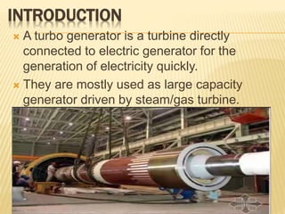
INDUSTRIAL TRAINING SEMINAR
Bharat Heavy Electricals
Limited, Ranipur, Haridwar
Submitted to:
Department of Electrical Engineering,
INSTITUTE OF TECHNOLOGY
for the partial fulfillment
of
Degree
Bachelors of Technology
Presented by: Unknown
15
11/09/2020
CONTENT
 Need of training
 Abstract
 Introduction
 Stator
 Rotor
 Insulation
 Excitation system
 Cooling system
 References
NEED OF TRAINING
• Higher productivity
• Quality improvement
• Reduction of learning time
• Interest in work
• Technology update
• Effective management
• Effective communication skill
ABSTRACT
 Training at B.H.E.L. has proved to be quite
faithful. It proved an opportunity for
encounter with such huge machine like
turbo-generators.
 It provides an opportunity to learn tech. Used
at proper place and time can save a lot of
labour.
INTRODUCTION
 A turbo generator is a turbine directly
connected to electric generator for the
generation of electricity quickly.
 They are mostly used as large capacity
generator driven by steam/gas turbine.
PRINCIPLE OF OPERATION
 Rotor winding is supplied with dc current
(through slip rings or brushless exciter) which
produces constant magnetic field.
 Three phase stator winding is laid in stator core.
 When generator is rotated (by turbines)
magnetic flux produced by rotor winding winding
also rotates.
 Voltage is induced in stator winding according to
Faraday’s law.
FARADAY’ S LAW
 E.M.F. (Voltage) is induced in a closed path due to
change of flux linkages and is proportional to the
rate of change of flux linkages.
 The change in flux linkages can be caused by
change in flux in a stationary coil or by motion of
coil with constant flux or both.
E = -N(dØ/dt )
COMPONENTS OF TURBO GENERATOR
 Stator
 Rotor
 Excitation System
The following auxiliaries are required for
operation :
 Bearings
 Cooling System
 Oil Supply System
STATOR
The stator consists of following parts:
1. Stator Frame
2. Stator Core
3. Stator Winding
4. Stator End Covers
5. Bushings
6. Generator Terminal Box
STATOR FRAME
 Rigid fabricated cylindrical
frame and is the heaviest
section in the generator.
 Withstands weight of core
and winding forces and
torques during operation.
 Provision for H₂/CO₂ filling.
 Foot plates for supporting on
foundation.
 Provision for H₂ coolers.
STATOR CORE
 The stator core is made from the insulated
electrical sheet laminations to minimize eddy
current losses. Each lamination layer is made of
individual sections.
Purpose of stator core :
 Support the stator winding.
 To provide mechanical support.
 To ensure the perfect link between the core and
rotor.
 To carry the magnetic flux generated by rotor
winding.
STATOR WINDING
 The stator winding of turbo
generator is three phase two layer
lap winding with the pitch of
winding so adjusted as to reduce
the 5th and 7th harmonics.
 The number of slots of three phase
power must be a multiple of 3 or 6.
 Each stator slot accommodates
two stator bars.
STATOR END COVERS
 The end covers are made up
of non magnetic material
(Aluminium casting) to reduce
stray load and eddy current
losses.
 They are employed with guide
vans on inner side for
ensuring uniform distribution
of air or gas.
BUSHINGS
 The bushings are bolted to the stator frame
at the exciter end.
 The beginning and ends of the three phase
windings are brought out from the stator
frame through bushings, which provides high
voltage insulation.
ROTOR
 Rotating part of turbo generator.
 A high strength alloy steel single forging
prepared by vacuum cast steel.
 Rotor of cylindrical type used in turbo generator.
 Rotor revolves in most modern generator at
speed of 3000 revolutions per minute.
ROTOR SHAFT
 The rotor shaft is cold rolled forging 26N1 or
MOV116 grade and it is imported from Japan
and Italy.
 Details of shaft are given here –
Length = 9 meter (approx.)
Diameter = 1 meter(approx.)
Material – alloy steel
Number of poles = 2
ROTOR WINDING
 The rotor of turbo generator accommodates
field winding.
 The winding consist of several coils inserted
into the slots and the series connected such
that two coils group to form one pole.
 The individual turn of coil are insulated
against each other by interlayer insulation.
INSULATION
 L-shaped strip of laminated epoxy glass fiber
with nomex filter(interlines) are used for slot
insulation.
EXCITATION SYSTEM
 The basic use of an excitation system is to
produce necessary DC for turbo generator
system.
PILOT EXCITER
 The three phase pilot exciter
has a revolving field with
permanent magnet poles.
 The armature winding is
housed on the stator.
 The three phase a.c.
generated by pilot exciter is
rectified and controlled by
AVR to provide variable d.c.
for exciting the main exciter.
AUTOMATIC VOLTAGE REGULATOR
(AVR)
 The main component in the
rectifier wheel is silicon
diode which are arranged in
AVR in three phase bridge
circuit.
 The direct current from
rectifier wheel is fed to DC
leads and then to the field
winding of the rotor.
MAIN EXCITER
 The three phase main exciter
has stationary field and rotating
armature.
 Thus, three phase a.c. power
is produced in main exciter
which is rectified by rotating
rectifier bridge and is fed to the
field winding of rotor (turbo
generator) through dc leads.
COOLING METHODS FOR TURBO
GENERATOR
 Air cooled T.G.
 Hydrogen cooling and hydrogen cooled
T.G.(THRI)
 Hydrogen/Water cooled T.G.(THDF)
AIR COOLED TURBO GENERATOR
Hot air
Cold air
 This type of cooling is
applicable for rating 30
MW-60 MW generators.
 In this type of turbo
generator there are
vertically side mounted
cooler in a separate
housing.
HYDROGEN COOLING AND HYDROGEN
COOLED TURBO GENERATOR
 To push up generator ratings hydrogen is used as
cooling medium.
 Size of cooler is small.
 Density of H₂ is only 0.07 times that of air and
therefore, power required to circulate H₂ is less.
 H₂ has heat transfer coefficient 1.5 times and thermal
conductivity is 7 times that of air.
HYDROGEN WATER COOLED TURBO
GENERATOR
 In large rating, hydrogen cooling is not
sufficient to remove the entire heat
generated.
 For additional cooling, a Primary Water(PW)
cooling system with demineralised water
flowing through the hollow stator conductor is
used.
 The rotor conductors are hydrogen cooled.

BHELppt

  • 1.
    INDUSTRIAL TRAINING SEMINAR BharatHeavy Electricals Limited, Ranipur, Haridwar Submitted to: Department of Electrical Engineering, INSTITUTE OF TECHNOLOGY for the partial fulfillment of Degree Bachelors of Technology Presented by: Unknown 15 11/09/2020
  • 2.
    CONTENT  Need oftraining  Abstract  Introduction  Stator  Rotor  Insulation  Excitation system  Cooling system  References
  • 3.
    NEED OF TRAINING •Higher productivity • Quality improvement • Reduction of learning time • Interest in work • Technology update • Effective management • Effective communication skill
  • 4.
    ABSTRACT  Training atB.H.E.L. has proved to be quite faithful. It proved an opportunity for encounter with such huge machine like turbo-generators.  It provides an opportunity to learn tech. Used at proper place and time can save a lot of labour.
  • 5.
    INTRODUCTION  A turbogenerator is a turbine directly connected to electric generator for the generation of electricity quickly.  They are mostly used as large capacity generator driven by steam/gas turbine.
  • 6.
    PRINCIPLE OF OPERATION Rotor winding is supplied with dc current (through slip rings or brushless exciter) which produces constant magnetic field.  Three phase stator winding is laid in stator core.  When generator is rotated (by turbines) magnetic flux produced by rotor winding winding also rotates.  Voltage is induced in stator winding according to Faraday’s law.
  • 7.
    FARADAY’ S LAW E.M.F. (Voltage) is induced in a closed path due to change of flux linkages and is proportional to the rate of change of flux linkages.  The change in flux linkages can be caused by change in flux in a stationary coil or by motion of coil with constant flux or both. E = -N(dØ/dt )
  • 8.
    COMPONENTS OF TURBOGENERATOR  Stator  Rotor  Excitation System The following auxiliaries are required for operation :  Bearings  Cooling System  Oil Supply System
  • 9.
    STATOR The stator consistsof following parts: 1. Stator Frame 2. Stator Core 3. Stator Winding 4. Stator End Covers 5. Bushings 6. Generator Terminal Box
  • 10.
    STATOR FRAME  Rigidfabricated cylindrical frame and is the heaviest section in the generator.  Withstands weight of core and winding forces and torques during operation.  Provision for H₂/CO₂ filling.  Foot plates for supporting on foundation.  Provision for H₂ coolers.
  • 11.
    STATOR CORE  Thestator core is made from the insulated electrical sheet laminations to minimize eddy current losses. Each lamination layer is made of individual sections. Purpose of stator core :  Support the stator winding.  To provide mechanical support.  To ensure the perfect link between the core and rotor.  To carry the magnetic flux generated by rotor winding.
  • 12.
    STATOR WINDING  Thestator winding of turbo generator is three phase two layer lap winding with the pitch of winding so adjusted as to reduce the 5th and 7th harmonics.  The number of slots of three phase power must be a multiple of 3 or 6.  Each stator slot accommodates two stator bars.
  • 13.
    STATOR END COVERS The end covers are made up of non magnetic material (Aluminium casting) to reduce stray load and eddy current losses.  They are employed with guide vans on inner side for ensuring uniform distribution of air or gas.
  • 14.
    BUSHINGS  The bushingsare bolted to the stator frame at the exciter end.  The beginning and ends of the three phase windings are brought out from the stator frame through bushings, which provides high voltage insulation.
  • 15.
    ROTOR  Rotating partof turbo generator.  A high strength alloy steel single forging prepared by vacuum cast steel.  Rotor of cylindrical type used in turbo generator.  Rotor revolves in most modern generator at speed of 3000 revolutions per minute.
  • 16.
    ROTOR SHAFT  Therotor shaft is cold rolled forging 26N1 or MOV116 grade and it is imported from Japan and Italy.  Details of shaft are given here – Length = 9 meter (approx.) Diameter = 1 meter(approx.) Material – alloy steel Number of poles = 2
  • 17.
    ROTOR WINDING  Therotor of turbo generator accommodates field winding.  The winding consist of several coils inserted into the slots and the series connected such that two coils group to form one pole.  The individual turn of coil are insulated against each other by interlayer insulation.
  • 18.
    INSULATION  L-shaped stripof laminated epoxy glass fiber with nomex filter(interlines) are used for slot insulation.
  • 19.
    EXCITATION SYSTEM  Thebasic use of an excitation system is to produce necessary DC for turbo generator system.
  • 20.
    PILOT EXCITER  Thethree phase pilot exciter has a revolving field with permanent magnet poles.  The armature winding is housed on the stator.  The three phase a.c. generated by pilot exciter is rectified and controlled by AVR to provide variable d.c. for exciting the main exciter.
  • 21.
    AUTOMATIC VOLTAGE REGULATOR (AVR) The main component in the rectifier wheel is silicon diode which are arranged in AVR in three phase bridge circuit.  The direct current from rectifier wheel is fed to DC leads and then to the field winding of the rotor.
  • 22.
    MAIN EXCITER  Thethree phase main exciter has stationary field and rotating armature.  Thus, three phase a.c. power is produced in main exciter which is rectified by rotating rectifier bridge and is fed to the field winding of rotor (turbo generator) through dc leads.
  • 23.
    COOLING METHODS FORTURBO GENERATOR  Air cooled T.G.  Hydrogen cooling and hydrogen cooled T.G.(THRI)  Hydrogen/Water cooled T.G.(THDF)
  • 24.
    AIR COOLED TURBOGENERATOR Hot air Cold air  This type of cooling is applicable for rating 30 MW-60 MW generators.  In this type of turbo generator there are vertically side mounted cooler in a separate housing.
  • 25.
    HYDROGEN COOLING ANDHYDROGEN COOLED TURBO GENERATOR  To push up generator ratings hydrogen is used as cooling medium.  Size of cooler is small.  Density of H₂ is only 0.07 times that of air and therefore, power required to circulate H₂ is less.  H₂ has heat transfer coefficient 1.5 times and thermal conductivity is 7 times that of air.
  • 26.
    HYDROGEN WATER COOLEDTURBO GENERATOR  In large rating, hydrogen cooling is not sufficient to remove the entire heat generated.  For additional cooling, a Primary Water(PW) cooling system with demineralised water flowing through the hollow stator conductor is used.  The rotor conductors are hydrogen cooled.