
Recommended
More Related Content
What's hot
What's hot (20)
Similar to alternator ppt.pptx
Similar to alternator ppt.pptx (20)
Recently uploaded
Recently uploaded (20)
alternator ppt.pptx
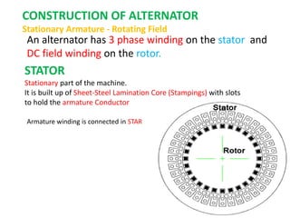
- 1. CONSTRUCTION OF ALTERNATOR Stationary Armature - Rotating Field An alternator has 3 phase winding on the stator and DC field winding on the rotor. STATOR Stationary part of the machine. It is built up of Sheet-Steel Lamination Core (Stampings) with slots to hold the armature Conductor Armature winding is connected in STAR
- 3. ROTOR: There are two types of rotor i) Salient Pole type {Projected Poles} ii) Non - Salient Pole type {Non – Projected Poles} Smooth Cylindrical Type
- 4. Salient Pole type {Projected Poles} It is also called Projected Poles. Poles are mounted on the larger circular frame. Made up of Thick Steel Laminations. Field Winding are connected in series. Ends of the field winding are connected to the DC Supply through Slip Rings Features Large Diameter and short Axial Length. Poles are Laminated to reduced Eddy Current Losses Employed for Low and Medium Speed 120 RMP to 500 RPM (Diesel & Hydraulic Turbines) This cannot be used for Large speed
- 5. DAMPER WINDING Pole faces are provided with damper winding Damper winding is useful in preventing Hunting EMF generated will be sinusoidal Copper Bar
- 7. II) NON SALIENT POLE TYPE Smooth cylindrical rotor or TURBO ALTERNATOR field winding used in high speed alternators driven by steam turbines . Features Smaller diameter and larger axial length compared to salient pole type machines, of the same rating. Less Windage loss. Speed 1200 RPM to 3000 RPM.. Better Balancing.. Noiseless Operation Flux distribution nearly sine wave Frequency 50 Hz Ns = 120 F / P Poles 2 4 6 Speed 3000 1500 1000
- 10. EMF Equation of an Alternator Let Φ = Flux per pole, Wb P = Number of Poles Ns = Synchronous Speed in RMP Z = Total Number of Conductors or coil sides in series / Phase Z = 2T T = Number of coils or Turns per phase Tph = Turns in series per phase = ( No. of slots * No. of cond. per slot) / (2 x 3) Zph = Conductor per phase Zph = Z / 3. No. of phase 3 Kc or Kp = Pitch factor or coil span factor Kd = Distribution factor Kp = Cos (α / 2 ) Kd = Sin (mβ / 2) m Sin(β / 2)
- 15. ARMATURE WINDING 3 Phase alternator carry 3 sets of winding arranged in slots Open circuited 6 terminals Can be connected in Star or Delta Armature Winding Classification 1. Single Layer and Double Layer Winding 2. Full Pitch and Short Pitch Winding 3. Concentrated and Distributed Winding
- 16. Single Layer and Double Layer Winding Single- layer winding • One coil-side occupies the total slot area • Used only in small ac machines Double- layer winding • Coil-sides in two layers • Double-layer winding is more common used above about 5kW machines The advantages of double-layer winding over single layer winding: a. Easier to manufacture and lower cost of the coils b. Fractional-slot winding can be used c. Chorded-winding is possible d. Lower-leakage reactance and therefore , better performance of the machine e. Better emf waveform in case of generators
- 17. POLE – PITCH It is the distance between the centres of pole faces of two adjacent poles is called pole pitch. Pole pitch = 180 Phase angle COIL : A coil consists of two coil sides. Placed in two separate slots SLOT PITCH: It is the phase angle between two adjustment slots COIL SPAN OR COIL PITCH It is the distance between two coil sides of a coil
- 18. Full Pitch and Short Pitch Winding Full Pitch Winding If the coil span is equal to pole pitch then the winding is called Full Pitch Winding Coil Span = Pole Pitch Short Pitch Winding If the coil span is less than Pole Pitch is called Short pitch winding e1 V e2 V e1 V e2 V e2 V
- 19. CONCENTRATED AND DISTRIBUTED WINDING Advantages of Short Chorded winding or Chorded Pitch Winding 1. Copper is saved 2. Mechanical strength of the coil is increased 3. Induced EMF in improved Slot Angle : The angular displacement between any two adjacent poles in electrical degree Slot angle (β) = 180 (Number of slots / Pole)
- 20. Synchronizing and Parallel operation Necessary Condition for Synchronization The process of switching of an alternator to another alternator or with a common Bus bar without any interruption is called Synchronization CONDITIONS FOR PARALLEL OPERATION 1. The terminal voltage of the incoming machine must be same as that of bus bar Voltage. 2. The frequency of the generated voltage of the incoming machine must be same as that of bus bar frequency. 3. The phase Sequence voltage of the incoming machine must be same as that of bus bar.(R Y B).
- 21. Advantages of Parallel operation Continuity of supply is possible when Breakdown or Shut down for maintenance of alternator in generating station Repair and Maintenance of individual machine can be carried out one after the other without effecting the normal routine work Depending upon the load requirement any number of alternator can be operated and the remaining can be put off It is economical and improves the efficiency of the generating station New alternator can be connected in parallel, when the demand increases. This reduces the capital cost of the system.
- 22. Methods of Synchronization of alternator Three Methods 1. Dark lamp method. 2. Bright Lamp Method 3. Synchroscope Method Conditions Should Satisfy 1. Voltage 2. Frequency 3. Phase Sequence
- 23. Synchronizing Current, Power and Torque E1 E2 Z1 = Ra + Xs Z2 = Ra + Xs E2 E1 E2 α Er E1 Isy Synchronizing Current Isy = Er / (Z1 + Z2) Synchronizing Power Psy = E1 x Isy Cos Φ1 Φ1 Synchronizing Torque Tsy = Psy / ( 2πNs / 60)
- 24. E1 NO LOAD E1 = E2 NO local Current Excitation of Alternator 1 Increasing E1 also increases > E2 Resultant Er.= E1-E2 Er =E1 – E2 Isy 90 E1 E2 Z1 = Ra + Xs Z2 = Ra + Xs I1 I2 2I Effect of Change in Excitation of Alternator in parallel Circulating current Isy Isy lags Er 90 Demagnetizing Effect REDUCES Eg Voltage Isy leads Er 90 Magnetizing Effect increases Eg Voltage