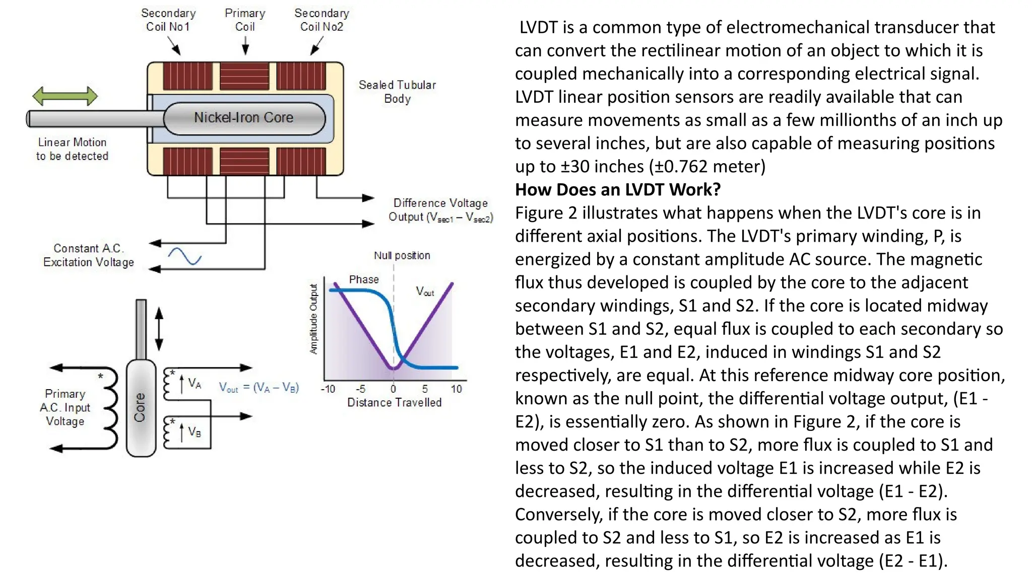
LVDT is acommon type of electromechanical transducer that
can convert the rectilinear motion of an object to which it is
coupled mechanically into a corresponding electrical signal.
LVDT linear position sensors are readily available that can
measure movements as small as a few millionths of an inch up
to several inches, but are also capable of measuring positions
up to ±30 inches (±0.762 meter)
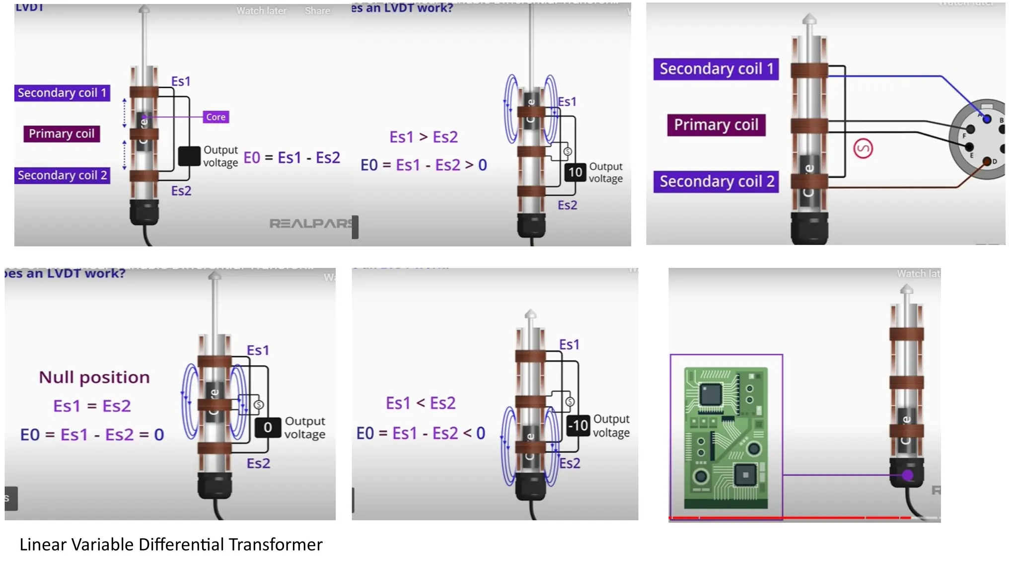
How Does an LVDT Work?
Figure 2 illustrates what happens when the LVDT's core is in
different axial positions. The LVDT's primary winding, P, is
energized by a constant amplitude AC source. The magnetic
flux thus developed is coupled by the core to the adjacent
secondary windings, S1 and S2. If the core is located midway
between S1 and S2, equal flux is coupled to each secondary so
the voltages, E1 and E2, induced in windings S1 and S2
respectively, are equal. At this reference midway core position,
known as the null point, the differential voltage output, (E1 -
E2), is essentially zero. As shown in Figure 2, if the core is
moved closer to S1 than to S2, more flux is coupled to S1 and
less to S2, so the induced voltage E1 is increased while E2 is
decreased, resulting in the differential voltage (E1 - E2).
Conversely, if the core is moved closer to S2, more flux is
coupled to S2 and less to S1, so E2 is increased as E1 is
decreased, resulting in the differential voltage (E2 - E1).
12.
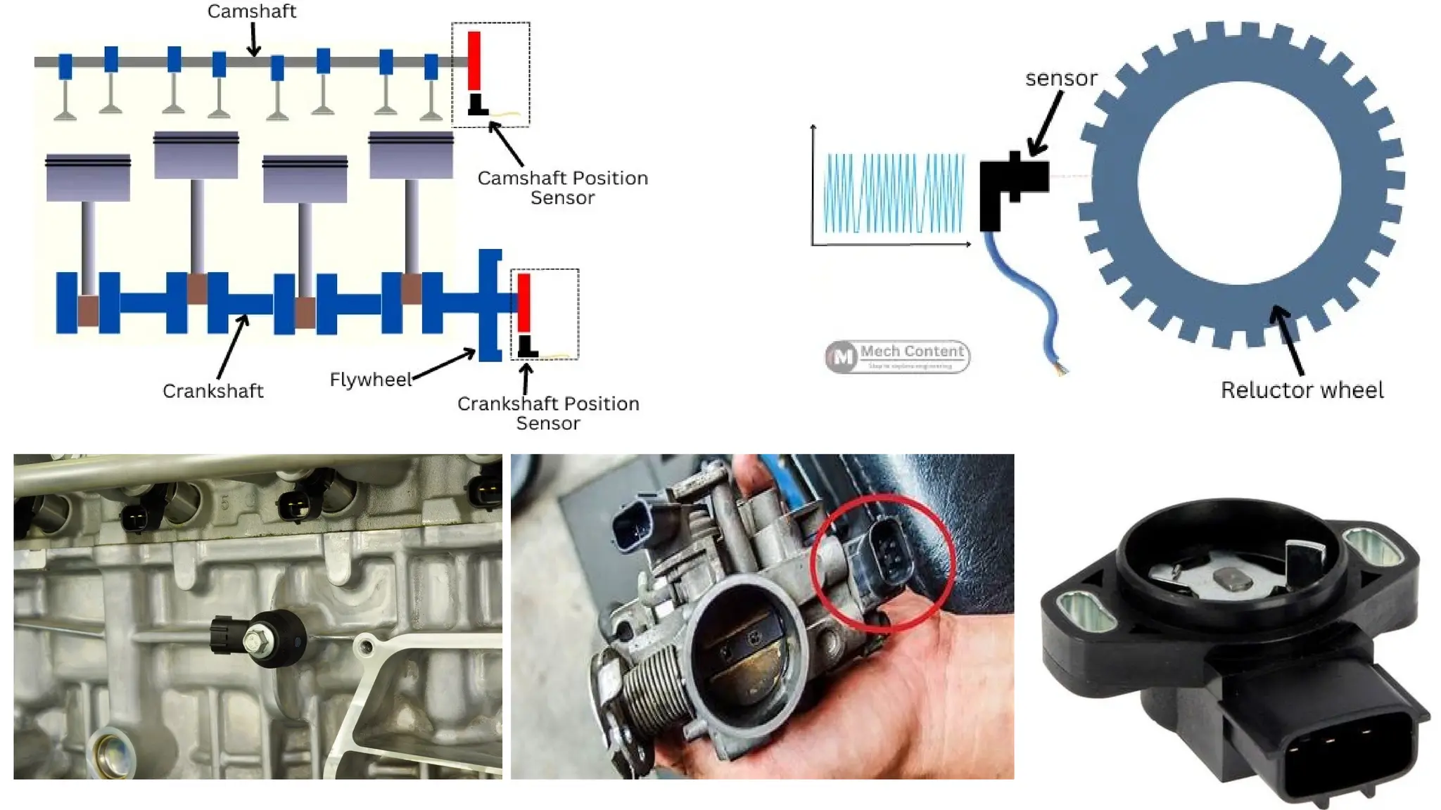
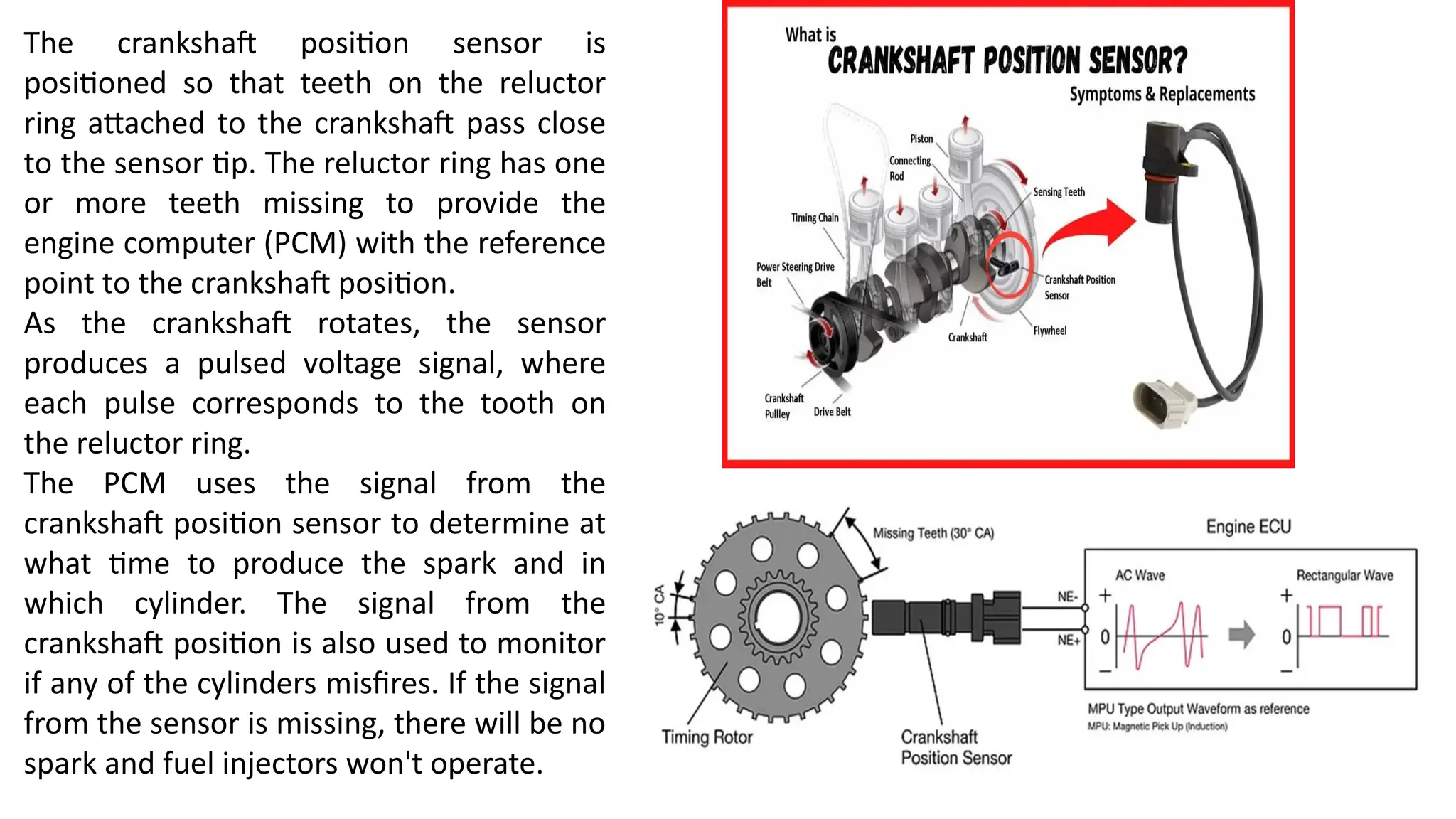
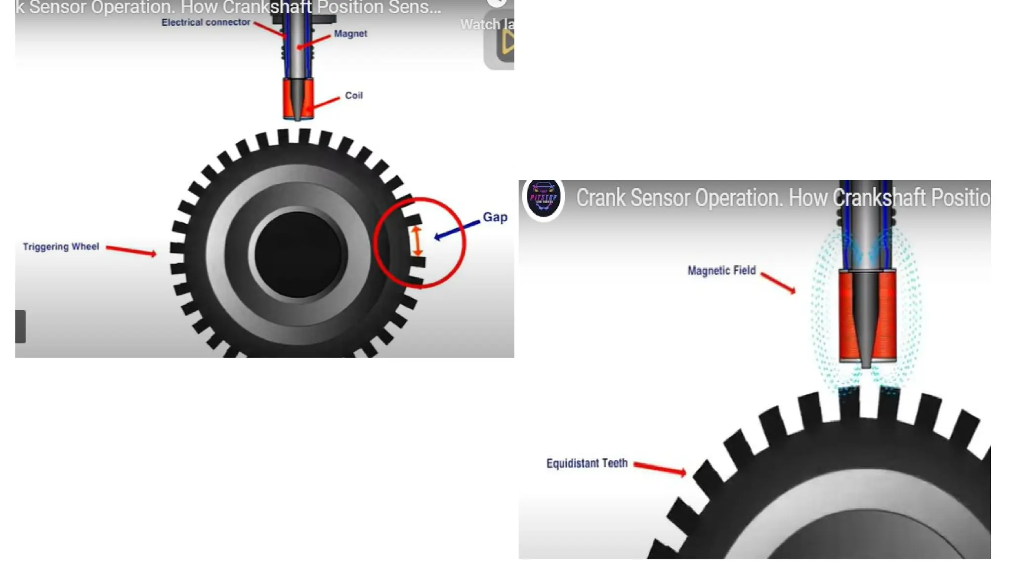
The crankshaft positionsensor is
positioned so that teeth on the reluctor
ring attached to the crankshaft pass close
to the sensor tip. The reluctor ring has one
or more teeth missing to provide the
engine computer (PCM) with the reference
point to the crankshaft position.
As the crankshaft rotates, the sensor
produces a pulsed voltage signal, where
each pulse corresponds to the tooth on
the reluctor ring.
The PCM uses the signal from the
crankshaft position sensor to determine at
what time to produce the spark and in
which cylinder. The signal from the
crankshaft position is also used to monitor
if any of the cylinders misfires. If the signal
from the sensor is missing, there will be no
spark and fuel injectors won't operate.
14.
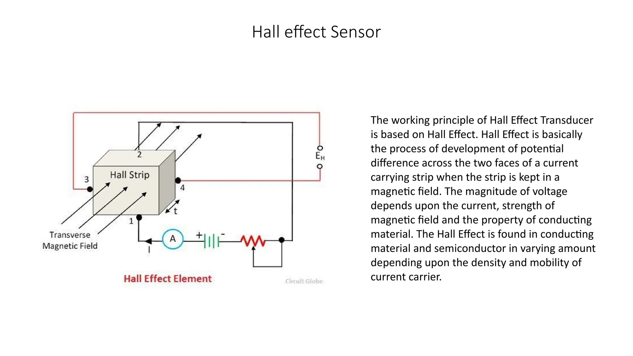
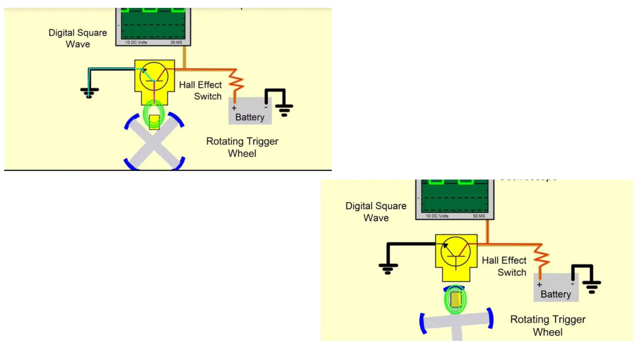
Hall effect Sensor
Theworking principle of Hall Effect Transducer
is based on Hall Effect. Hall Effect is basically
the process of development of potential
difference across the two faces of a current
carrying strip when the strip is kept in a
magnetic field. The magnitude of voltage
depends upon the current, strength of
magnetic field and the property of conducting
material. The Hall Effect is found in conducting
material and semiconductor in varying amount
depending upon the density and mobility of
current carrier.
17.
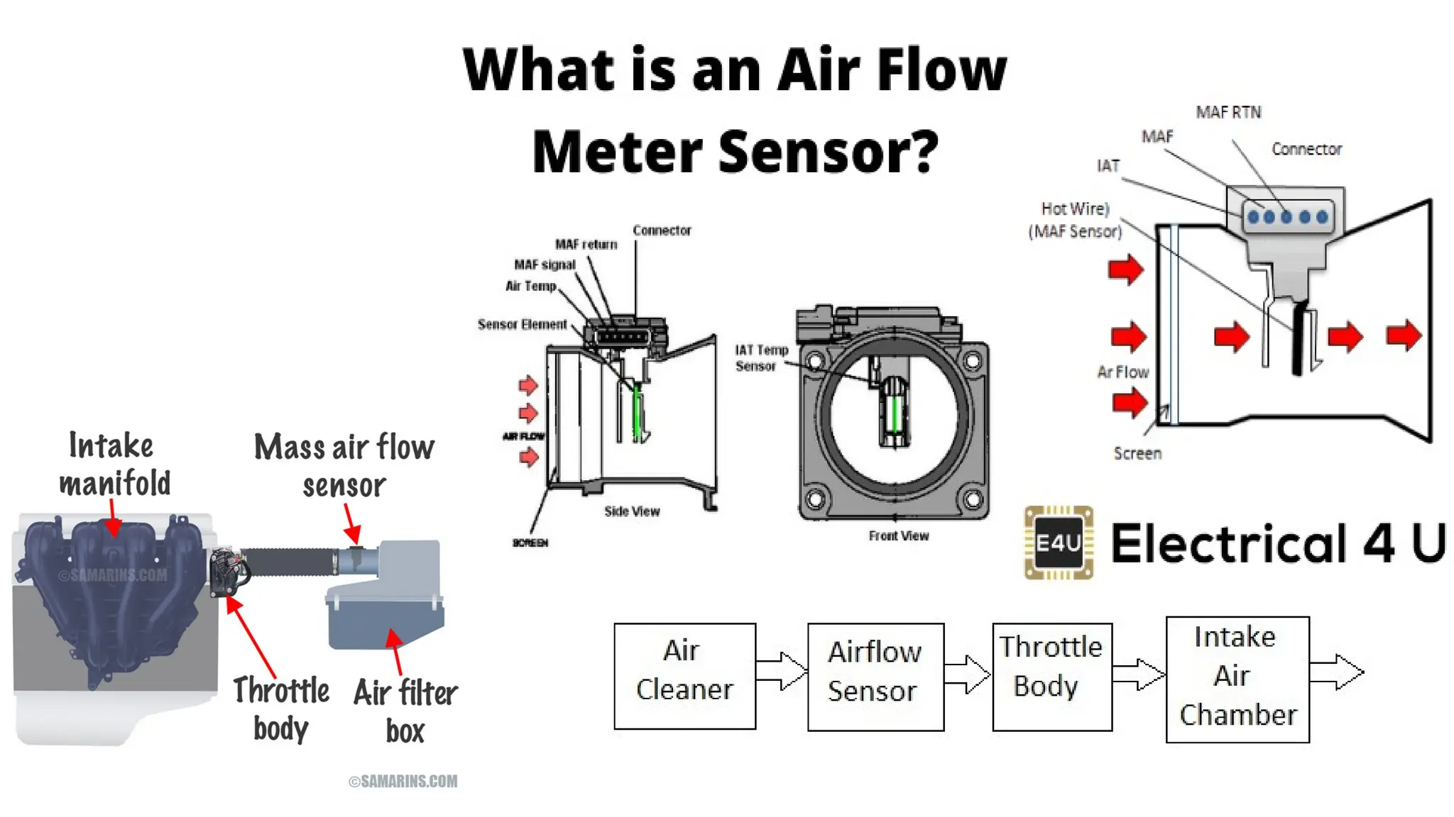
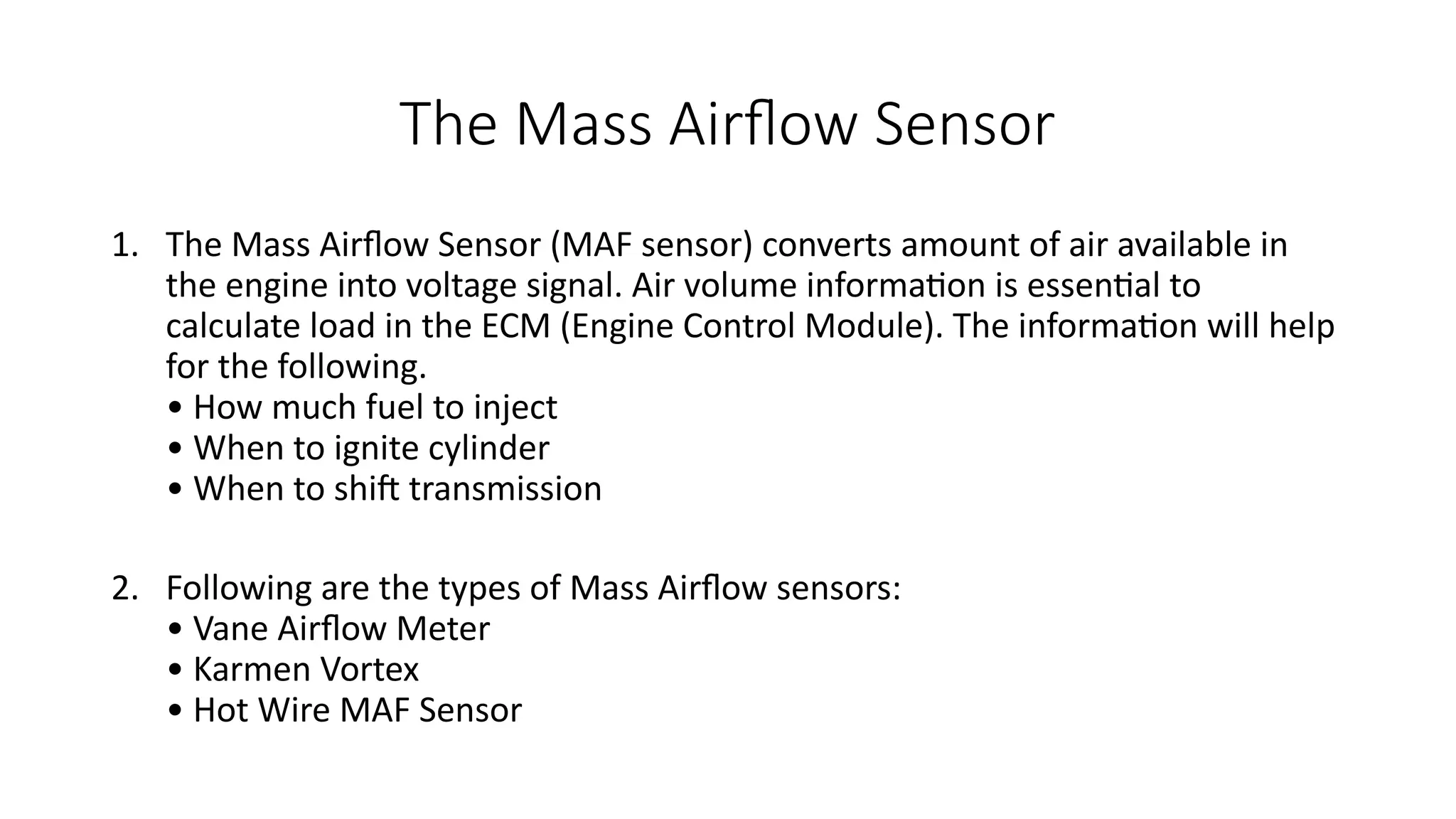
The Mass AirflowSensor
1. The Mass Airflow Sensor (MAF sensor) converts amount of air available in
the engine into voltage signal. Air volume information is essential to
calculate load in the ECM (Engine Control Module). The information will help
for the following.
• How much fuel to inject
• When to ignite cylinder
• When to shift transmission
2. Following are the types of Mass Airflow sensors:
• Vane Airflow Meter
• Karmen Vortex
• Hot Wire MAF Sensor
18.
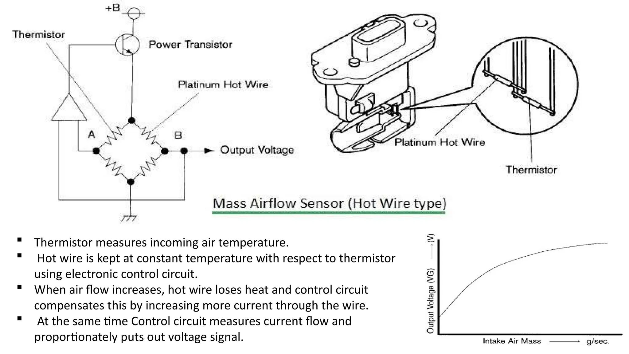
Thermistor measuresincoming air temperature.
Hot wire is kept at constant temperature with respect to thermistor
using electronic control circuit.
When air flow increases, hot wire loses heat and control circuit
compensates this by increasing more current through the wire.
At the same time Control circuit measures current flow and
proportionately puts out voltage signal.
19.
Temperature sensor
• Thedevice which sense the variation in the temperature is referred
as temperature sensor. The Temperature sensors can be divided into
four main categories as mentioned below.
• Resistance Temperature Detectors (RTD)
• Thermocouples
• Thermistor
• Ultrasonic transducers
20.
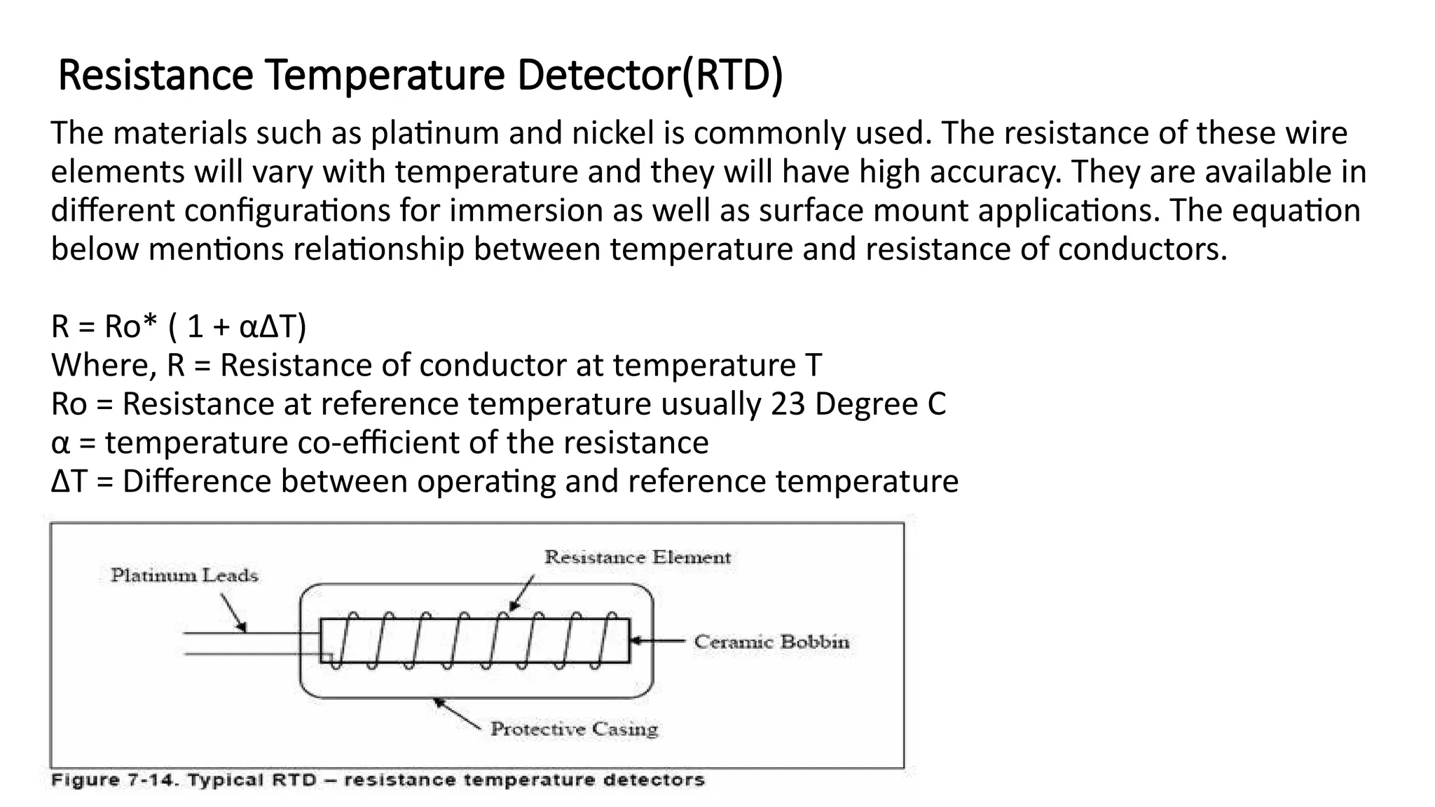
Resistance Temperature Detector(RTD)
Thematerials such as platinum and nickel is commonly used. The resistance of these wire
elements will vary with temperature and they will have high accuracy. They are available in
different configurations for immersion as well as surface mount applications. The equation
below mentions relationship between temperature and resistance of conductors.
R = Ro* ( 1 + αΔT)
Where, R = Resistance of conductor at temperature T
Ro = Resistance at reference temperature usually 23 Degree C
α = temperature co-efficient of the resistance
ΔT = Difference between operating and reference temperature
21.
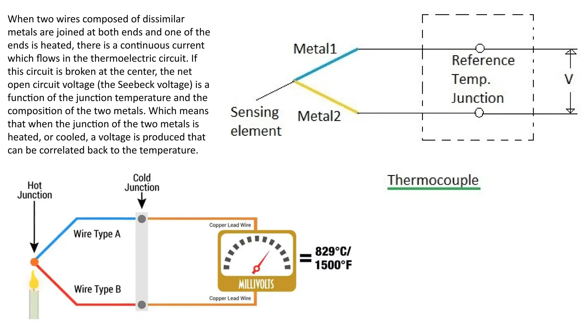
When two wirescomposed of dissimilar
metals are joined at both ends and one of the
ends is heated, there is a continuous current
which flows in the thermoelectric circuit. If
this circuit is broken at the center, the net
open circuit voltage (the Seebeck voltage) is a
function of the junction temperature and the
composition of the two metals. Which means
that when the junction of the two metals is
heated, or cooled, a voltage is produced that
can be correlated back to the temperature.
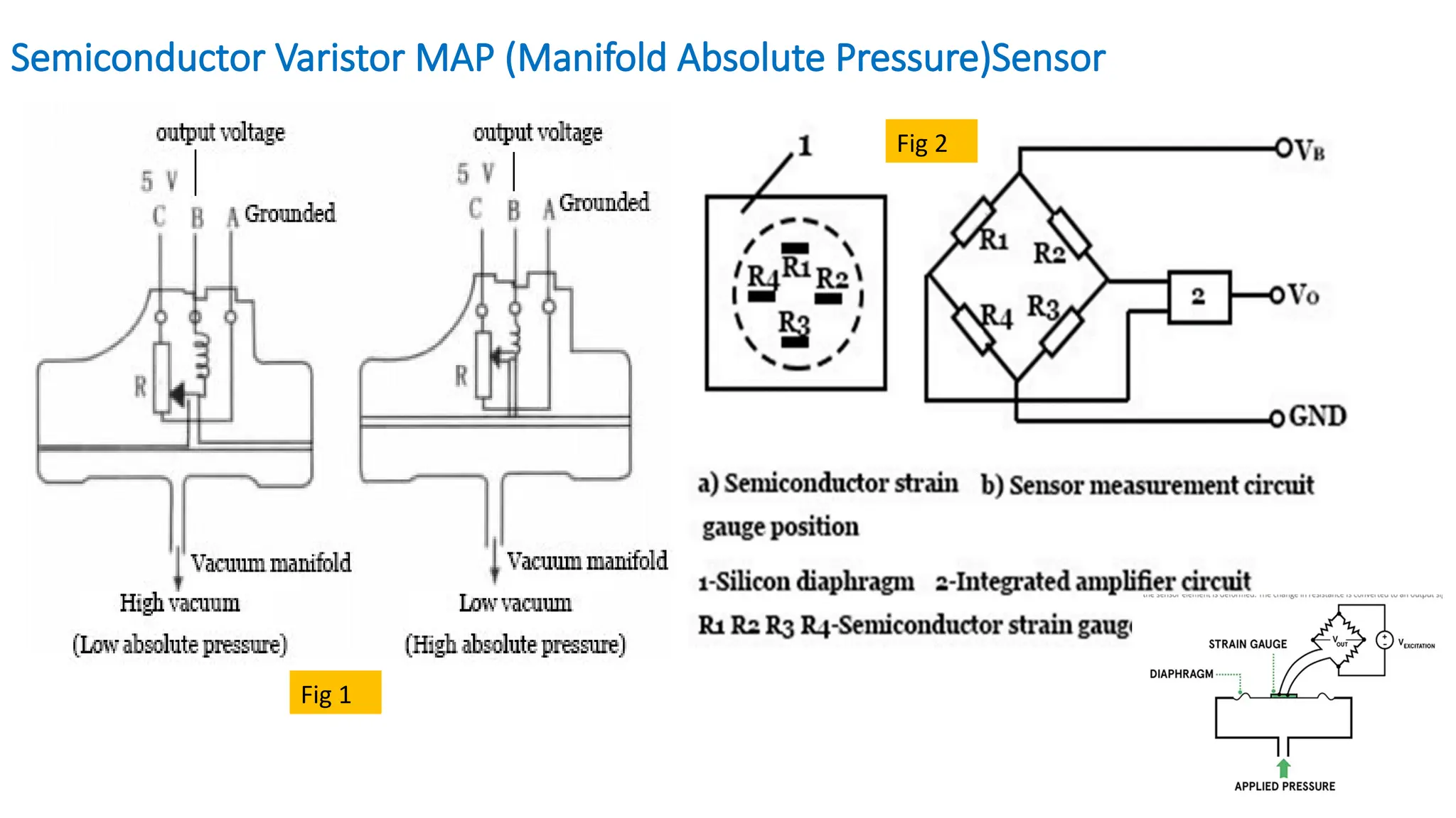
• The MAPsensor detects the absolute pressure of the intake manifold behind the throttle. It
detects the absolute pressure change in the manifold according to the engine speed and
load, and then converts it into a signal voltage and sends it to the engine control unit (ECU).
The ECU controls the basic fuel injection volume according to the signal voltage.
• There are many types of MAP sensors, including varistor type and capacitive type.
• Figure 1 shows the connection between the varistor type MAP sensor and the computer.
Figure 2 is the working principle of the varistor type MAP sensor. The R in Figure 1 is the
strain resistance. R1, R2, R3, R4 in Figure 2 form a Wheatstone bridge and are bonded to
the silicon diaphragm together.
• The silicon diaphragm can be deformed under the action of the absolute pressure in the
manifold, which causes the resistance value of the strain resistor R to change. The higher
the absolute pressure in the manifold, the greater the deformation of the silicon diaphragm
and the greater the resistance change of the resistance R. That is, the mechanical change of
the silicon diaphragm is converted into an electrical signal, which is then amplified by the
integrated circuit and output to the ECU
24.
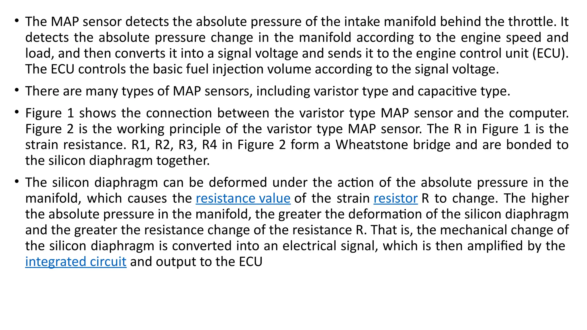
Piezoresistive Pressure sensor
Thebasic principle of the piezoresistive pressure sensor is to use a strain gauge made from a conductive
material that changes its electrical resistance when it is stretched. The strain gauge can be attached to a
diaphragm that recognises a change in resistance when the sensor element is deformed. The change in
resistance is converted to an output signal.
25.
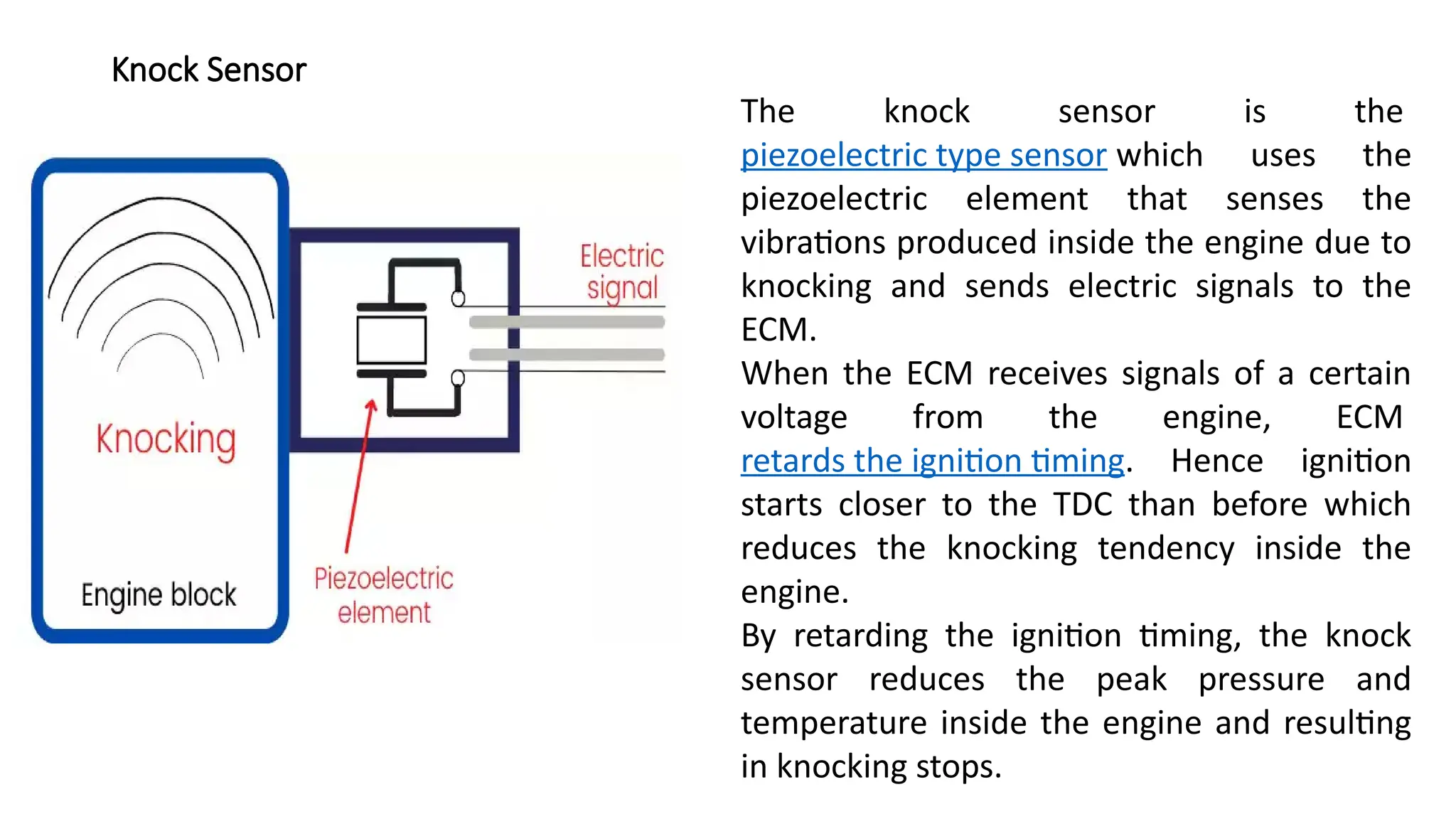
Knock Sensor
The knocksensor is the
piezoelectric type sensor which uses the
piezoelectric element that senses the
vibrations produced inside the engine due to
knocking and sends electric signals to the
ECM.
When the ECM receives signals of a certain
voltage from the engine, ECM
retards the ignition timing. Hence ignition
starts closer to the TDC than before which
reduces the knocking tendency inside the
engine.
By retarding the ignition timing, the knock
sensor reduces the peak pressure and
temperature inside the engine and resulting
in knocking stops.
26.
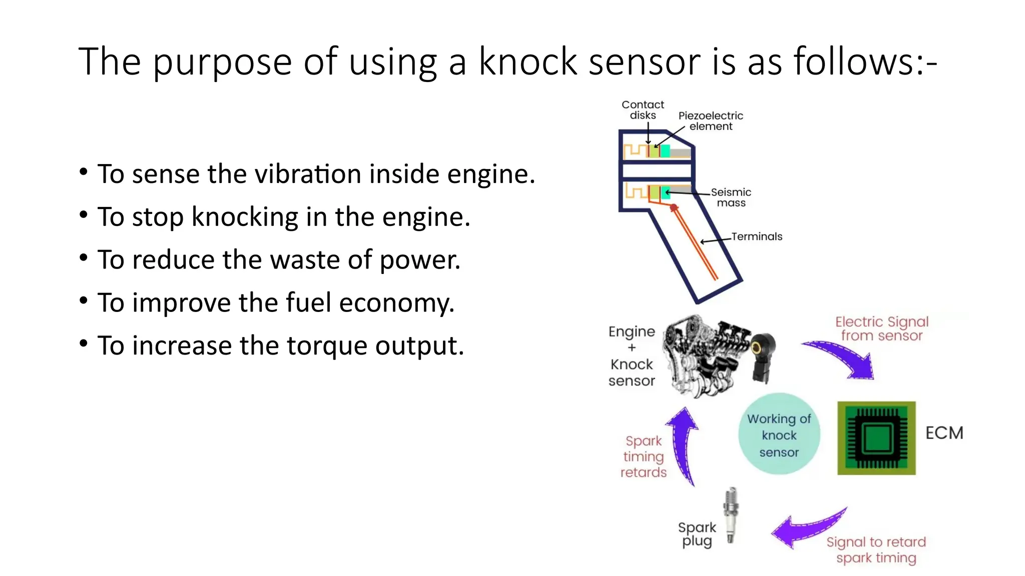
The purpose ofusing a knock sensor is as follows:-
• To sense the vibration inside engine.
• To stop knocking in the engine.
• To reduce the waste of power.
• To improve the fuel economy.
• To increase the torque output.
28.
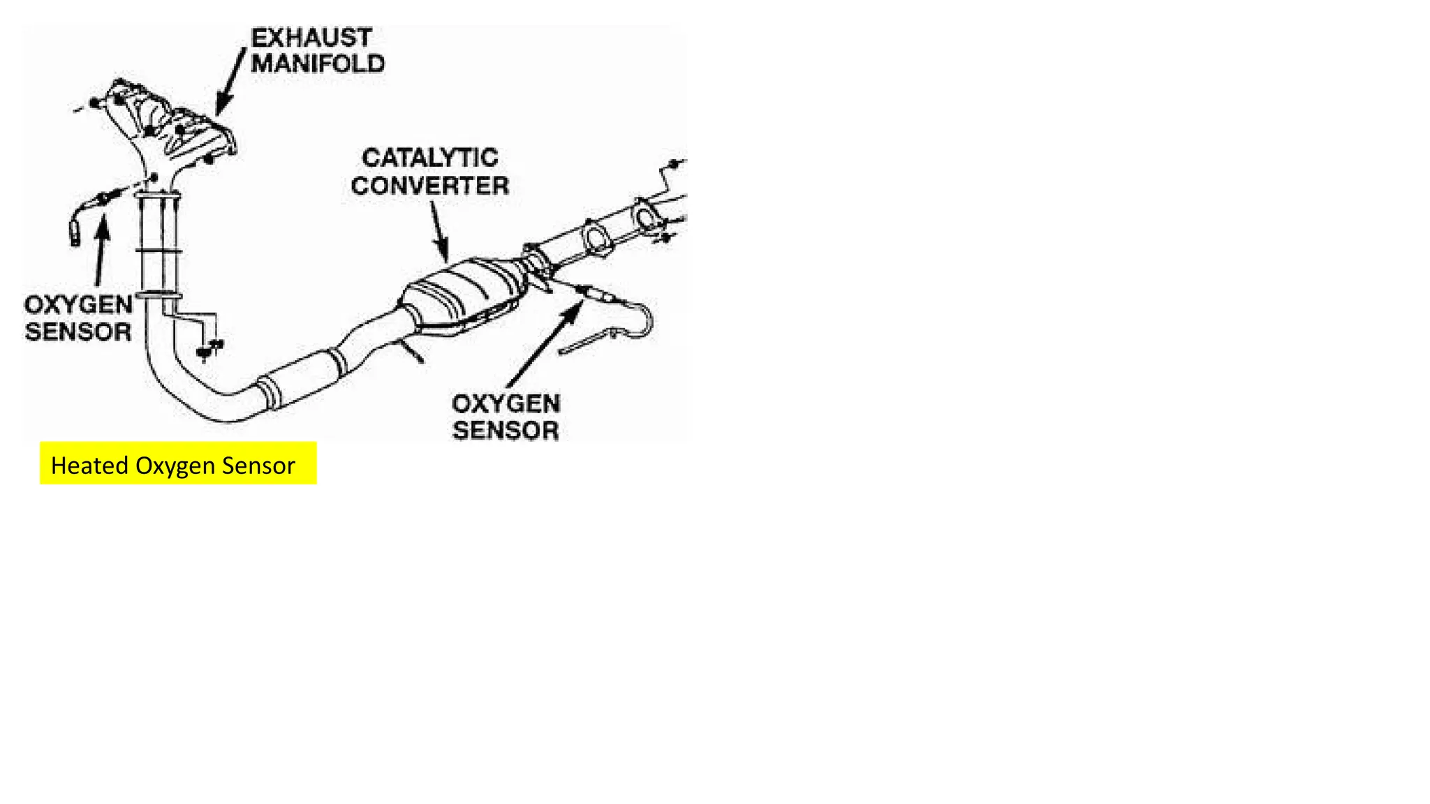
Oxygen Sensor
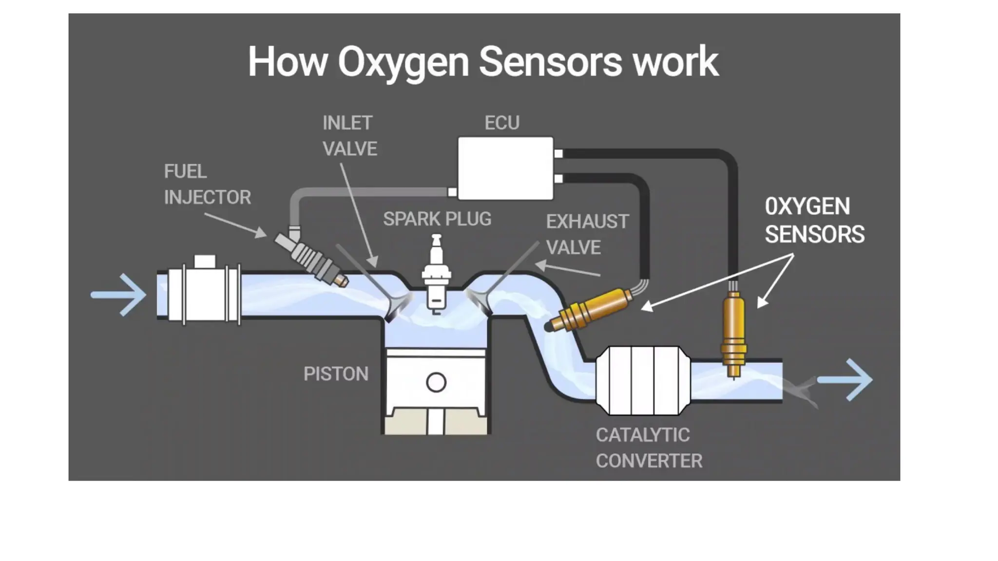
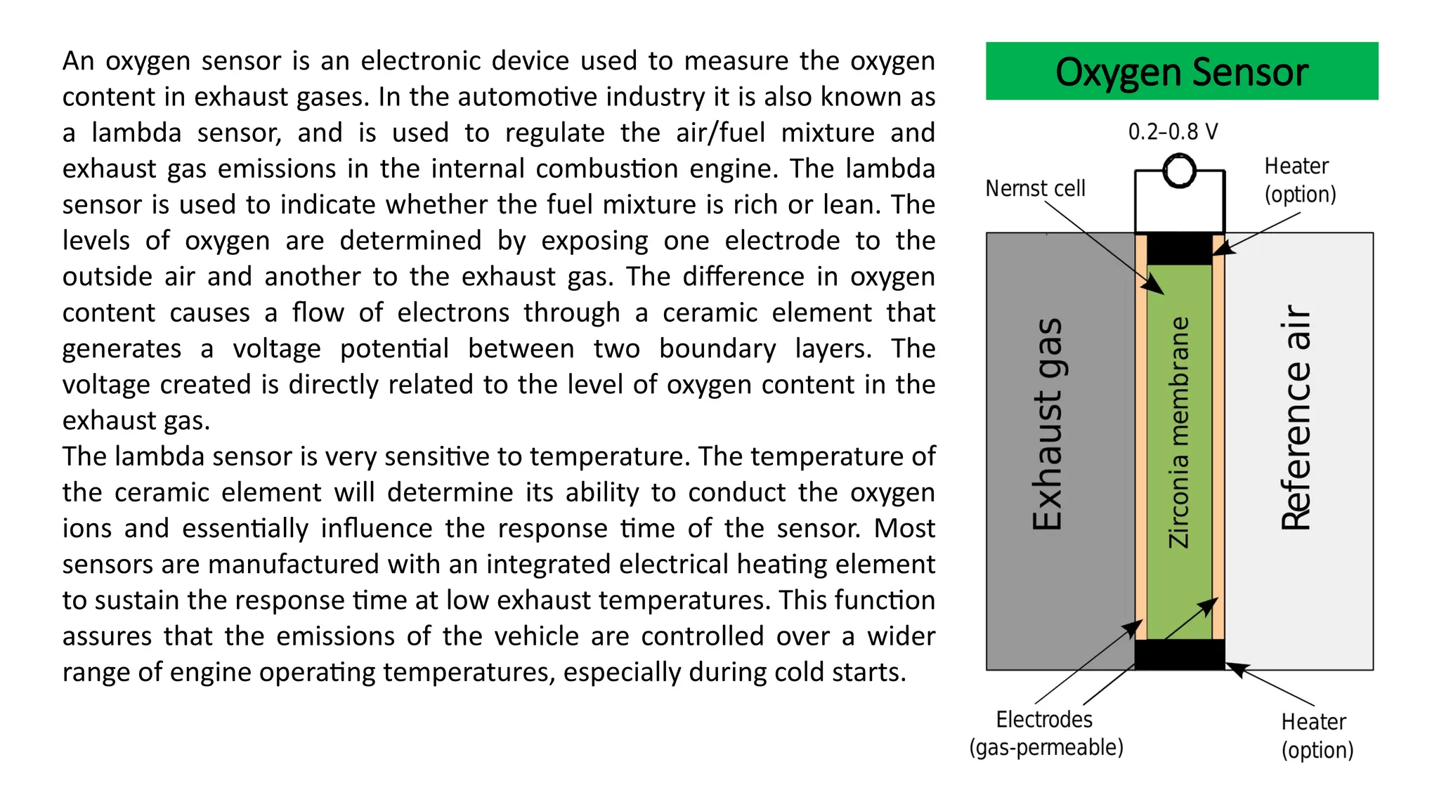
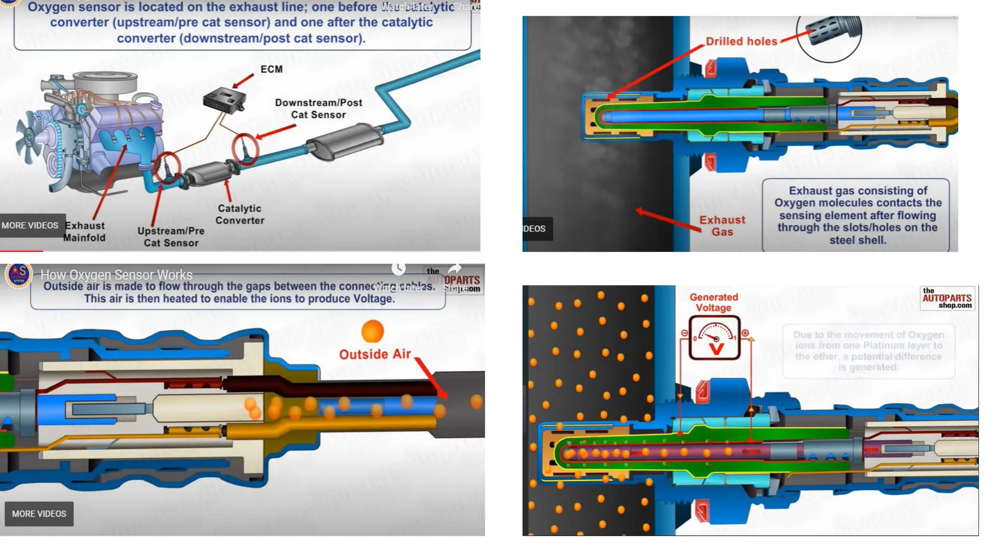
An oxygensensor is an electronic device used to measure the oxygen
content in exhaust gases. In the automotive industry it is also known as
a lambda sensor, and is used to regulate the air/fuel mixture and
exhaust gas emissions in the internal combustion engine. The lambda
sensor is used to indicate whether the fuel mixture is rich or lean. The
levels of oxygen are determined by exposing one electrode to the
outside air and another to the exhaust gas. The difference in oxygen
content causes a flow of electrons through a ceramic element that
generates a voltage potential between two boundary layers. The
voltage created is directly related to the level of oxygen content in the
exhaust gas.
The lambda sensor is very sensitive to temperature. The temperature of
the ceramic element will determine its ability to conduct the oxygen
ions and essentially influence the response time of the sensor. Most
sensors are manufactured with an integrated electrical heating element
to sustain the response time at low exhaust temperatures. This function
assures that the emissions of the vehicle are controlled over a wider
range of engine operating temperatures, especially during cold starts.
29.
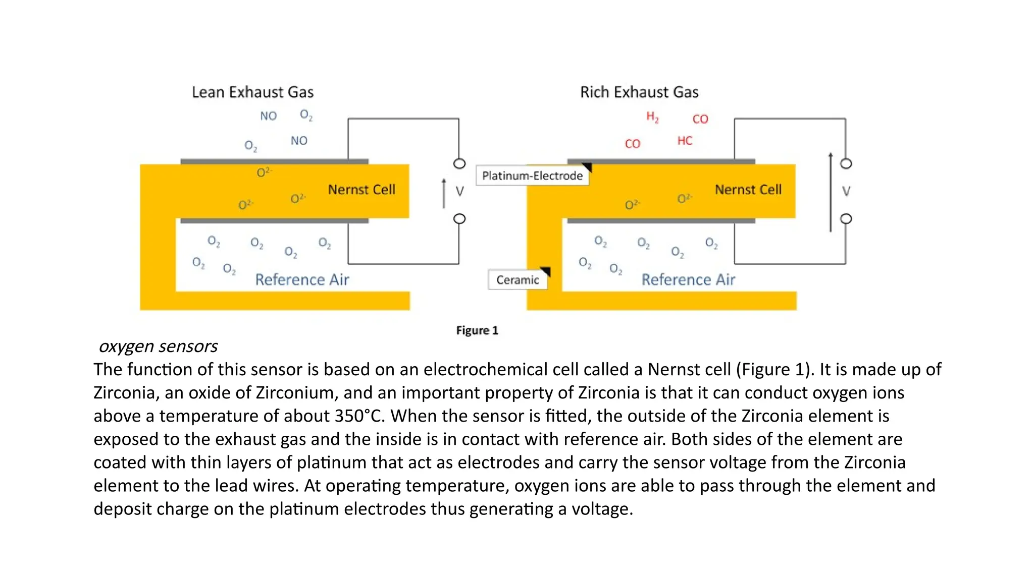
oxygen sensors
The functionof this sensor is based on an electrochemical cell called a Nernst cell (Figure 1). It is made up of
Zirconia, an oxide of Zirconium, and an important property of Zirconia is that it can conduct oxygen ions
above a temperature of about 350°C. When the sensor is fitted, the outside of the Zirconia element is
exposed to the exhaust gas and the inside is in contact with reference air. Both sides of the element are
coated with thin layers of platinum that act as electrodes and carry the sensor voltage from the Zirconia
element to the lead wires. At operating temperature, oxygen ions are able to pass through the element and
deposit charge on the platinum electrodes thus generating a voltage.
30.
• It isbasically an on/off switch in that it can determine if the mixture is
lean or rich, but it doesn't tell the ECU how lean or how rich the mix
is. It communicates with the ECU via the voltage it produces.
• If the AFR is rich, a HIGH signal voltage is generated across the
electrodes due to the difference in oxygen concentration present
across the two sides of the element.
• Conversely, if the AFR is lean, a LOW voltage is generated across the
electrodes due to the small difference in oxygen content between
exhaust gases and the reference air inside the sensor.
32.
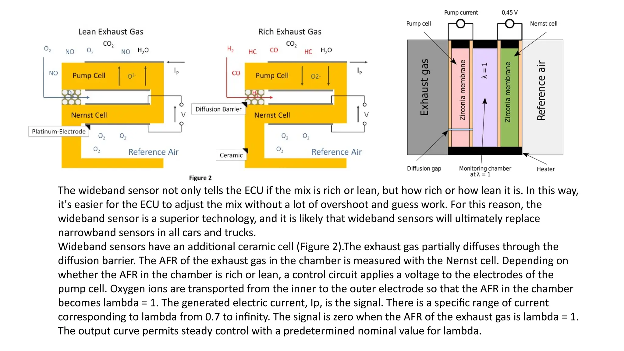
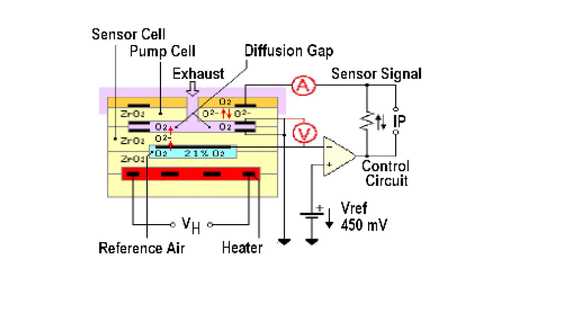
The wideband sensornot only tells the ECU if the mix is rich or lean, but how rich or how lean it is. In this way,
it's easier for the ECU to adjust the mix without a lot of overshoot and guess work. For this reason, the
wideband sensor is a superior technology, and it is likely that wideband sensors will ultimately replace
narrowband sensors in all cars and trucks.
Wideband sensors have an additional ceramic cell (Figure 2).The exhaust gas partially diffuses through the
diffusion barrier. The AFR of the exhaust gas in the chamber is measured with the Nernst cell. Depending on
whether the AFR in the chamber is rich or lean, a control circuit applies a voltage to the electrodes of the
pump cell. Oxygen ions are transported from the inner to the outer electrode so that the AFR in the chamber
becomes lambda = 1. The generated electric current, Ip, is the signal. There is a specific range of current
corresponding to lambda from 0.7 to infinity. The signal is zero when the AFR of the exhaust gas is lambda = 1.
The output curve permits steady control with a predetermined nominal value for lambda.
35.
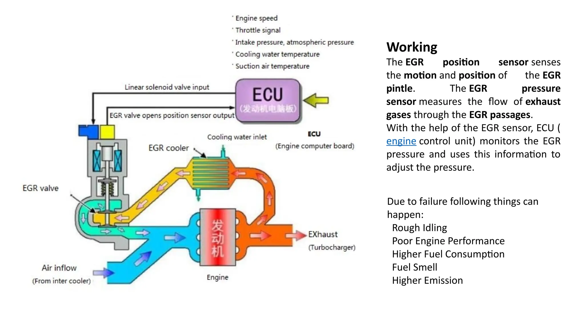
Working
The EGR positionsensor senses
the motion and position of the EGR
pintle. The EGR pressure
sensor measures the flow of exhaust
gases through the EGR passages.
With the help of the EGR sensor, ECU (
engine control unit) monitors the EGR
pressure and uses this information to
adjust the pressure.
Due to failure following things can
happen:
Rough Idling
Poor Engine Performance
Higher Fuel Consumption
Fuel Smell
Higher Emission
36.
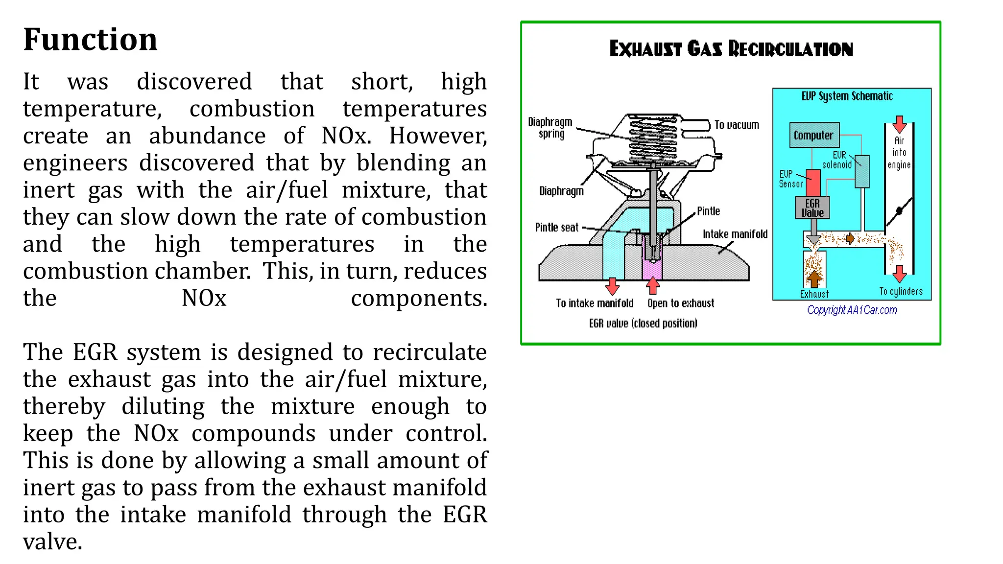
Function
It was discoveredthat short, high
temperature, combustion temperatures
create an abundance of NOx. However,
engineers discovered that by blending an
inert gas with the air/fuel mixture, that
they can slow down the rate of combustion
and the high temperatures in the
combustion chamber. This, in turn, reduces
the NOx components.
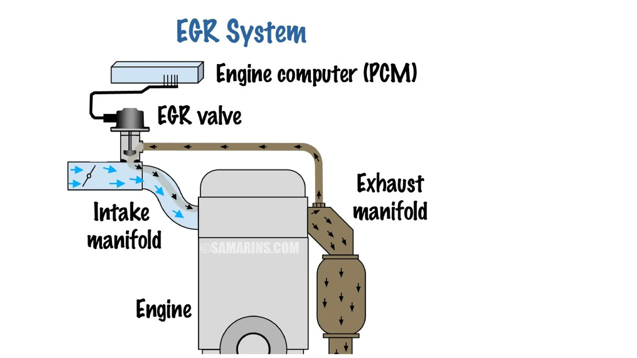
The EGR system is designed to recirculate
the exhaust gas into the air/fuel mixture,
thereby diluting the mixture enough to
keep the NOx compounds under control.
This is done by allowing a small amount of
inert gas to pass from the exhaust manifold
into the intake manifold through the EGR
valve.
37.
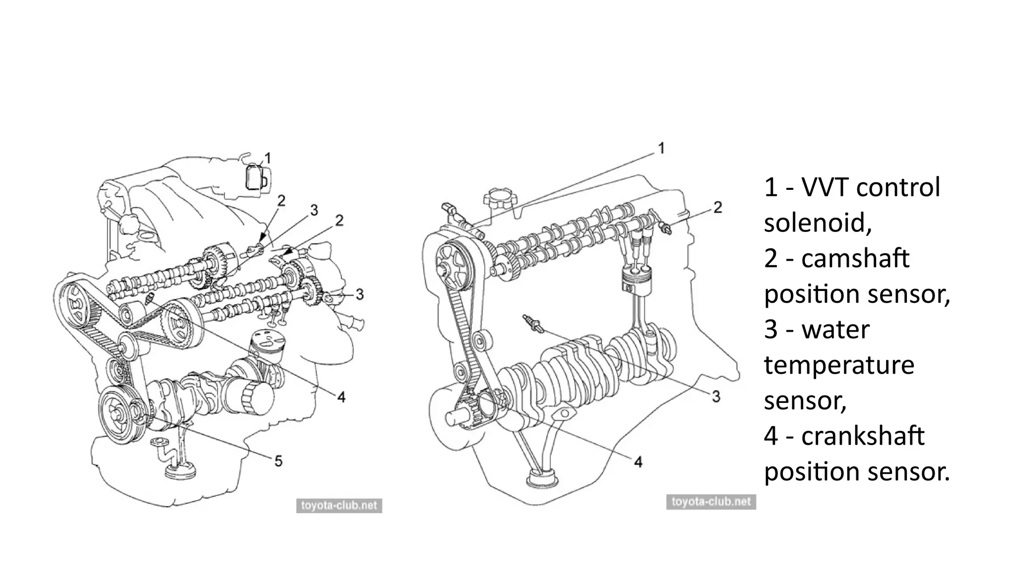
1 - VVTcontrol
solenoid,
2 - camshaft
position sensor,
3 - water
temperature
sensor,
4 - crankshaft
position sensor.
38.
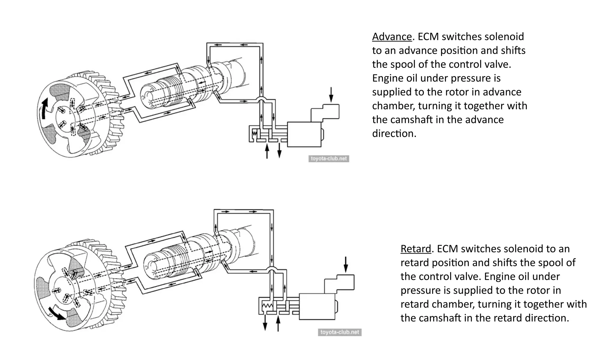
Advance. ECM switchessolenoid
to an advance position and shifts
the spool of the control valve.
Engine oil under pressure is
supplied to the rotor in advance
chamber, turning it together with
the camshaft in the advance
direction.
Retard. ECM switches solenoid to an
retard position and shifts the spool of
the control valve. Engine oil under
pressure is supplied to the rotor in
retard chamber, turning it together with
the camshaft in the retard direction.


![@&$%{<<><}{{Sensors][[[]] used in engine.ppt](https://cdn.slidesharecdn.com/ss_thumbnails/sensorsusedinefi-241005063801-504e3d07-thumbnail.jpg?width=640&height=640&fit=bounds)


![Engine management system[ EMS ] or Engine Control Unit [ ECU ]](https://cdn.slidesharecdn.com/ss_thumbnails/enginemanagementsystem-170920182131-thumbnail.jpg?width=640&height=640&fit=bounds)


