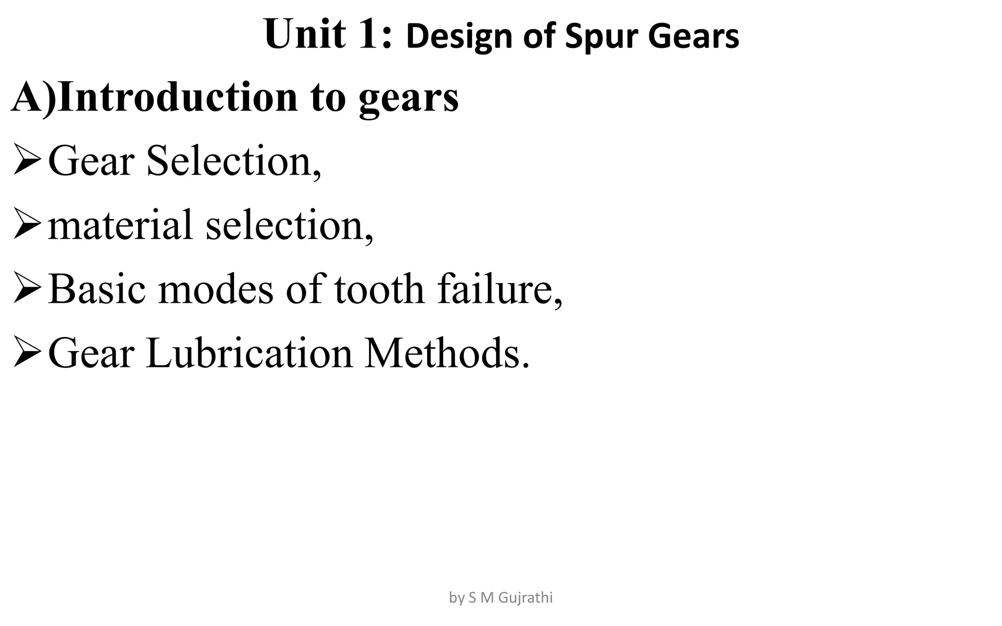
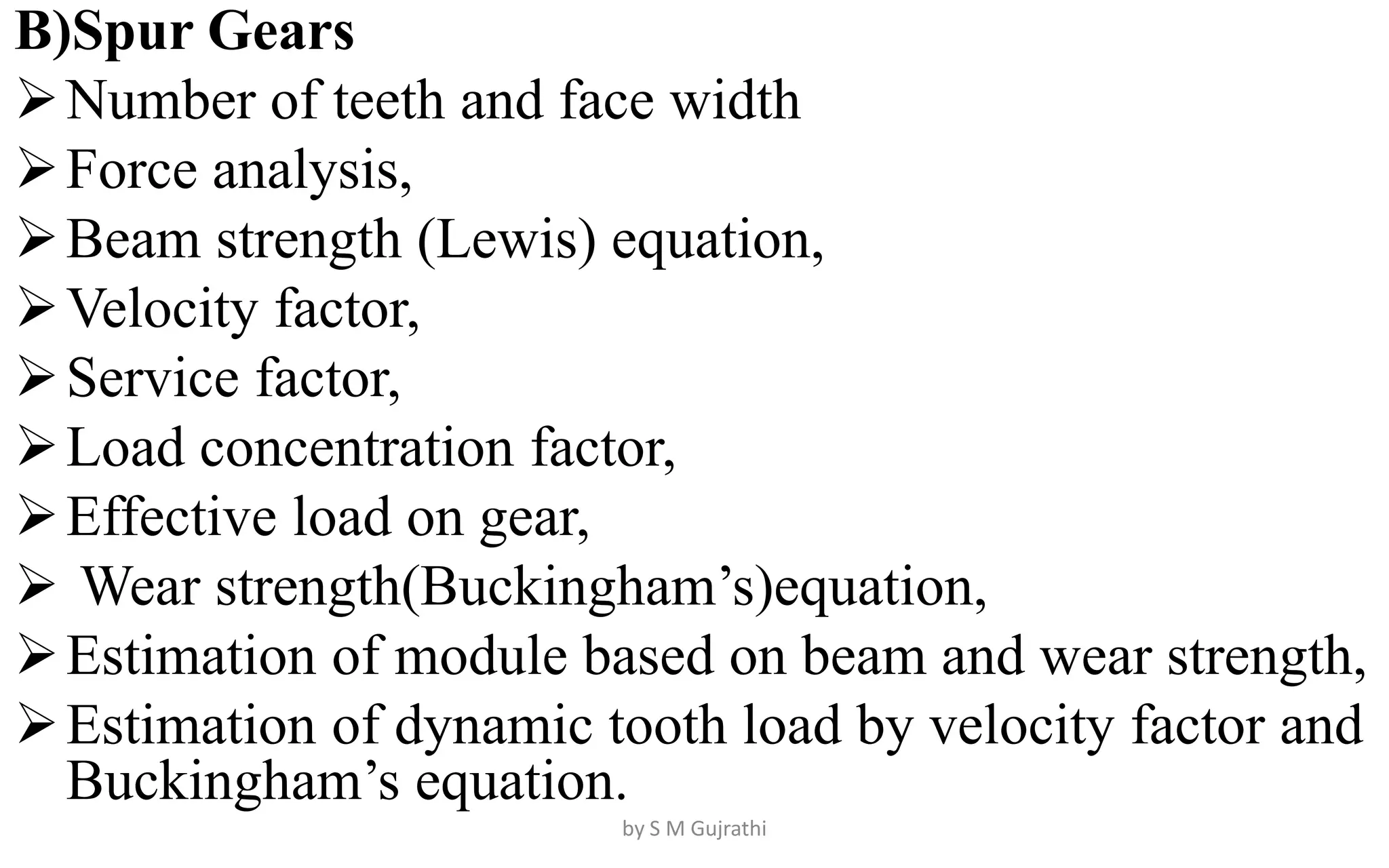
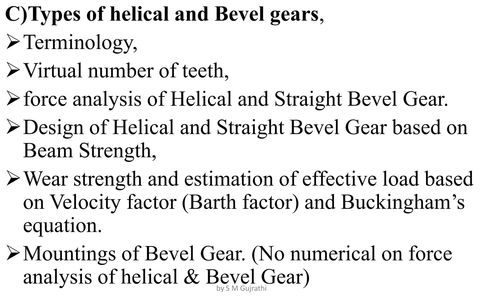
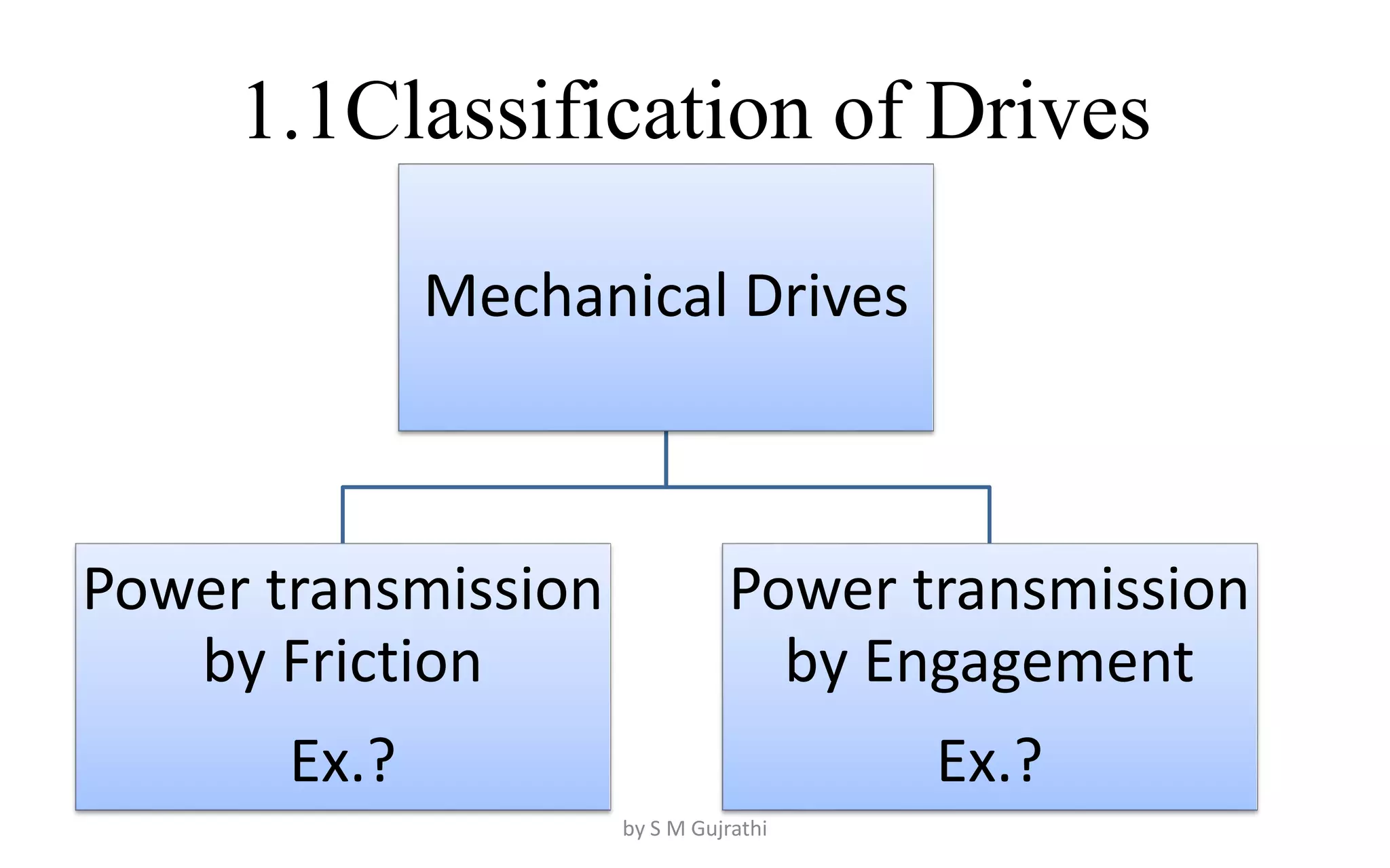
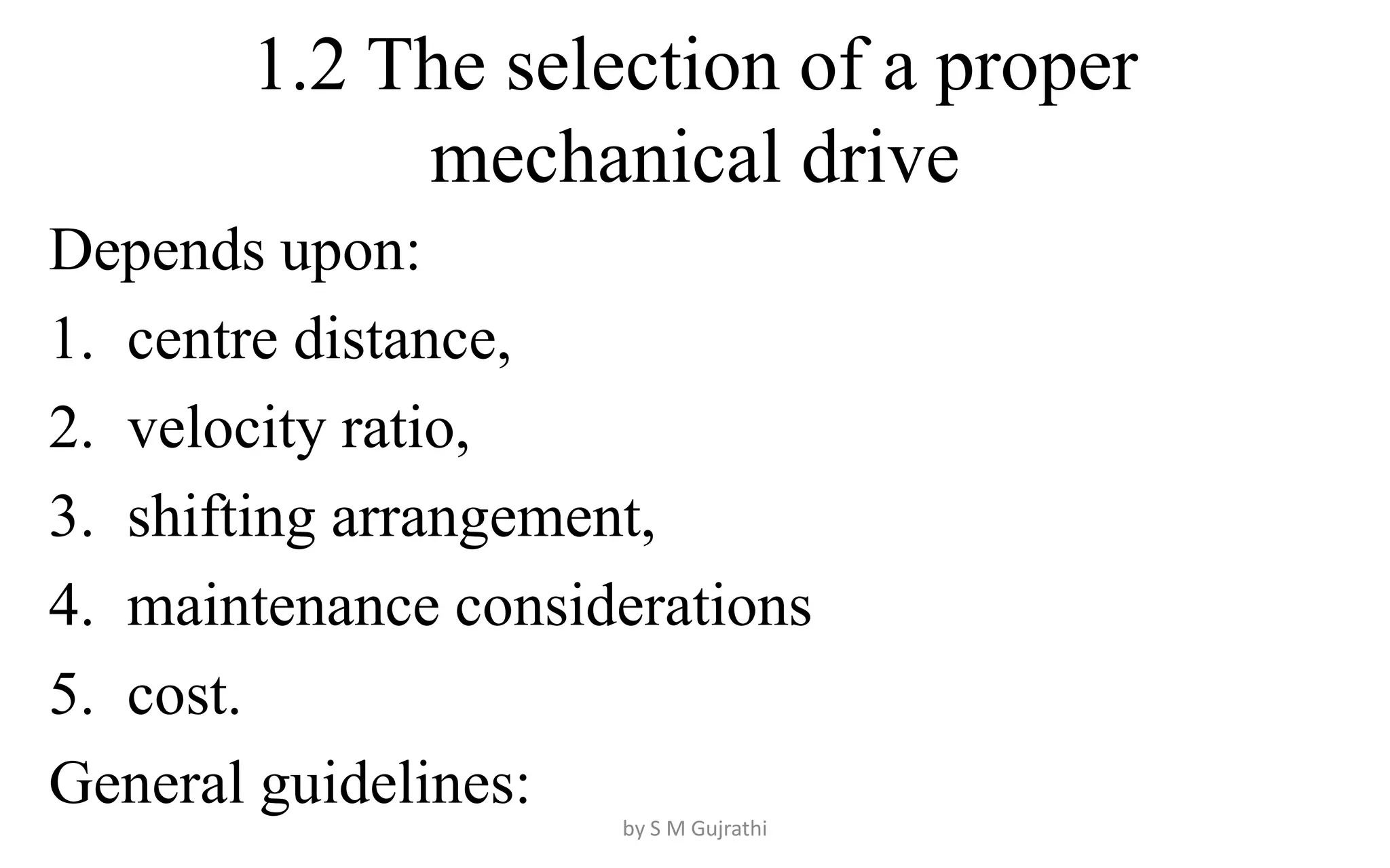
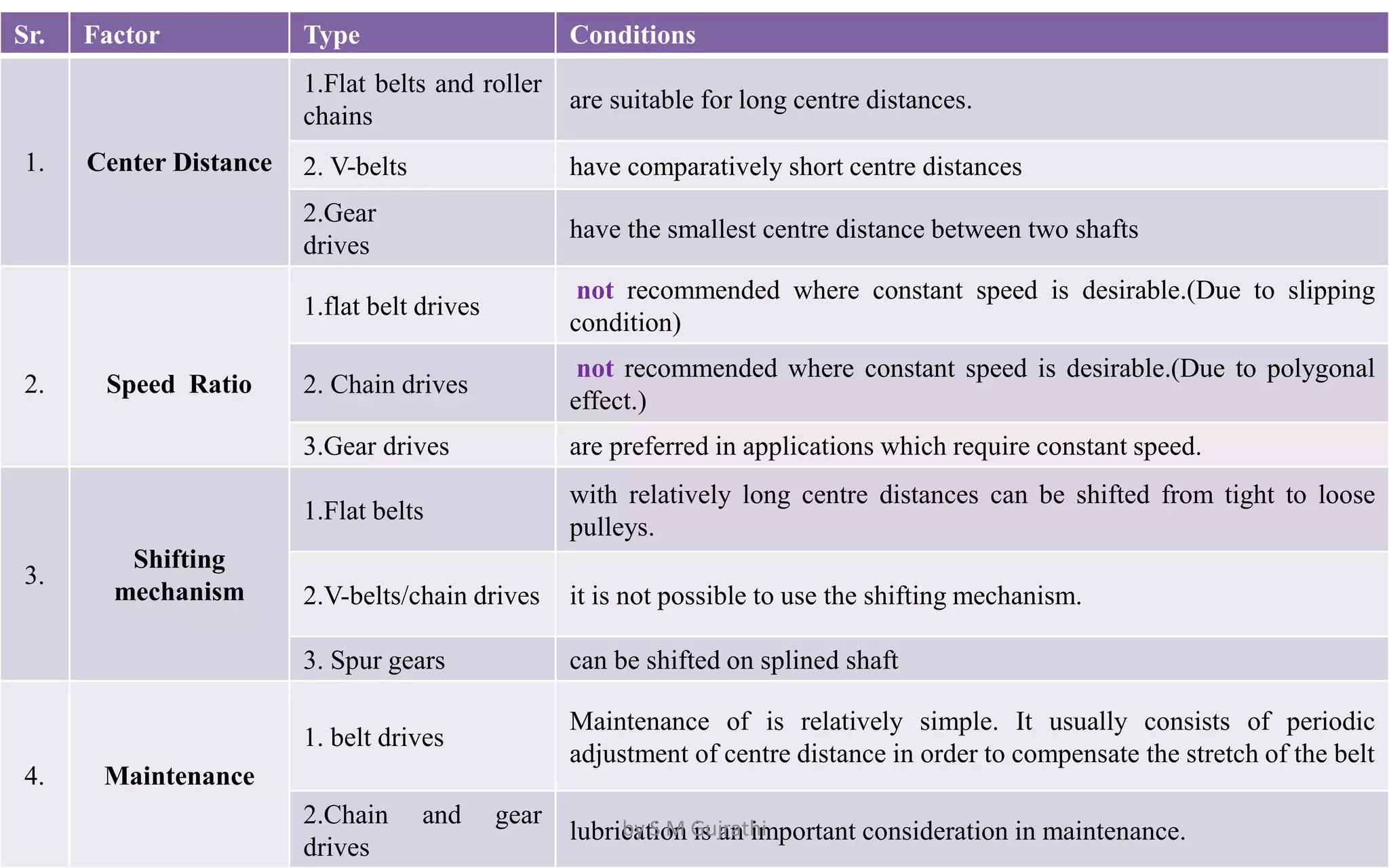
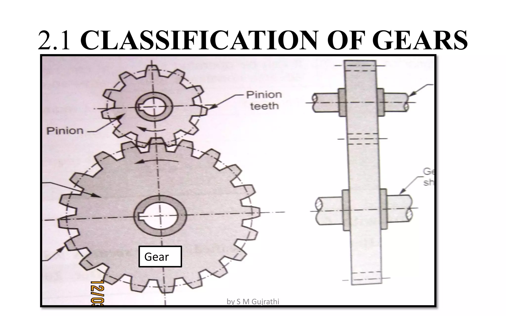
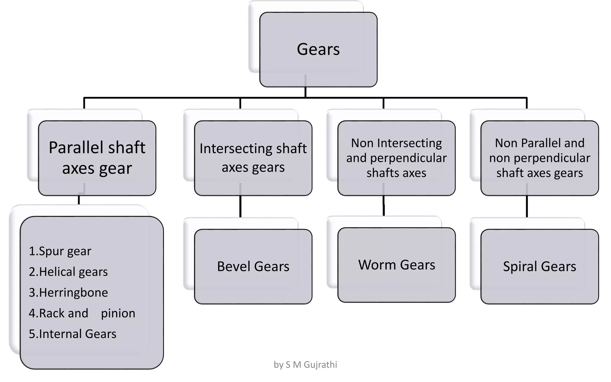
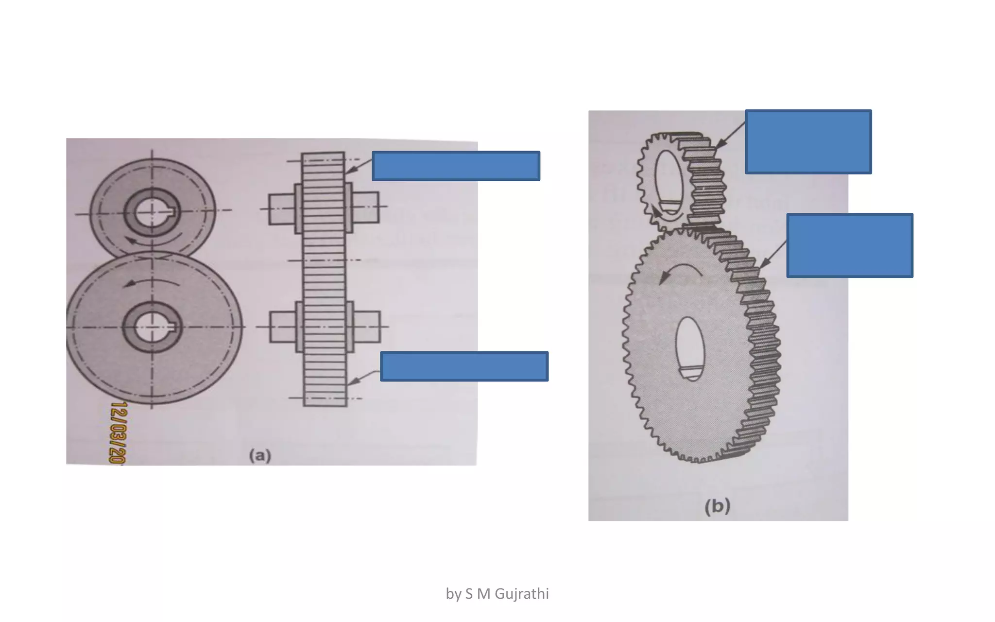
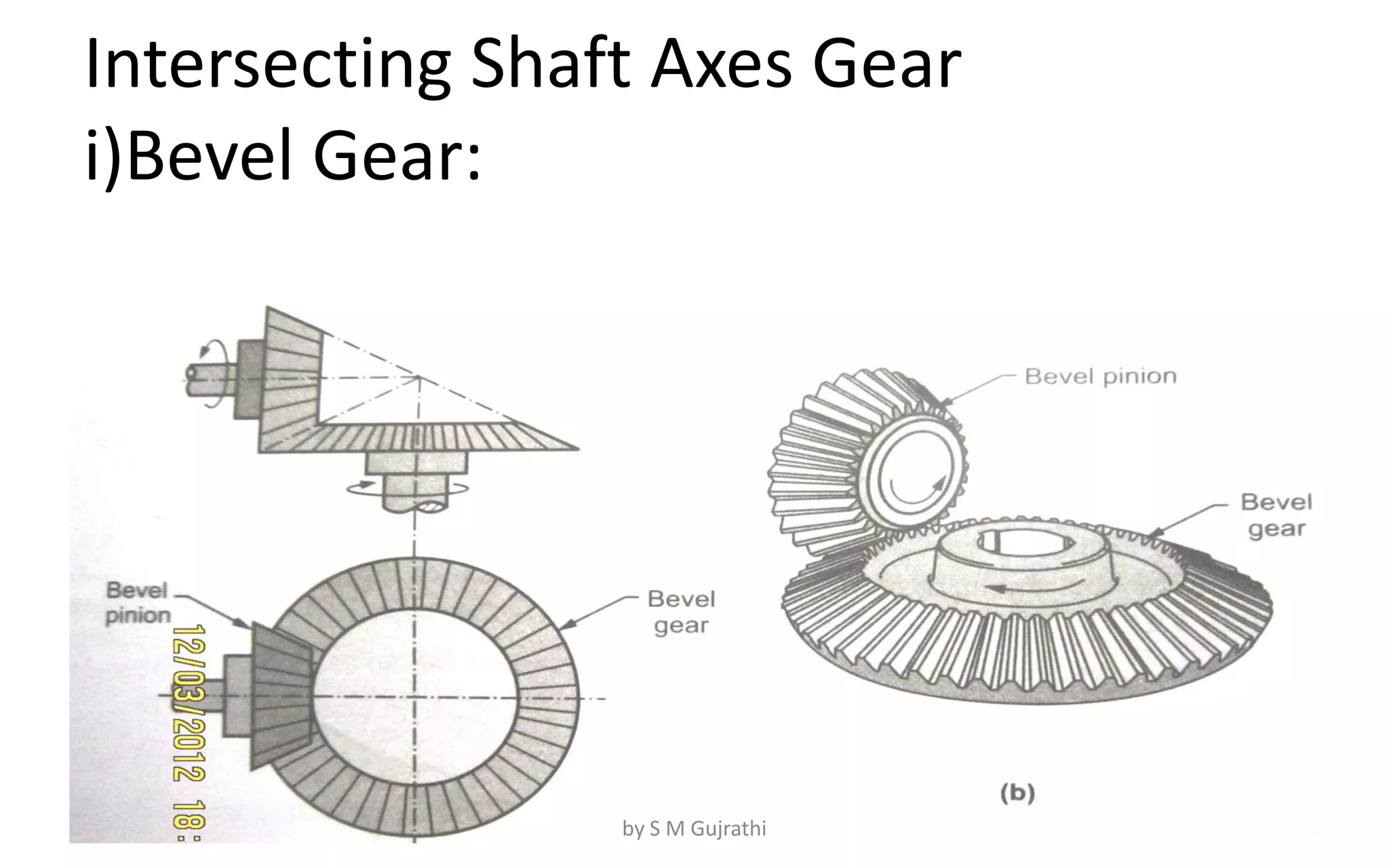
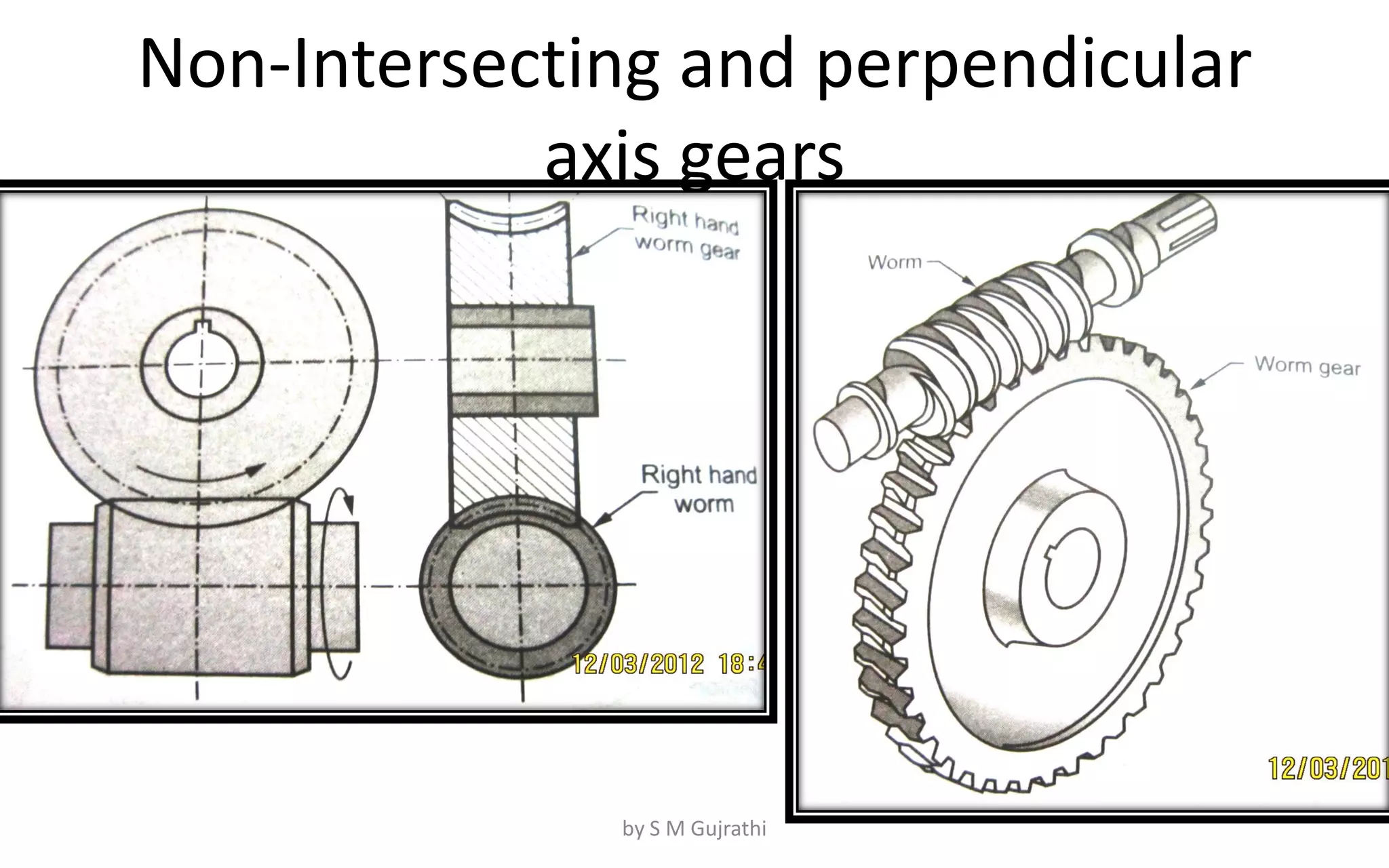
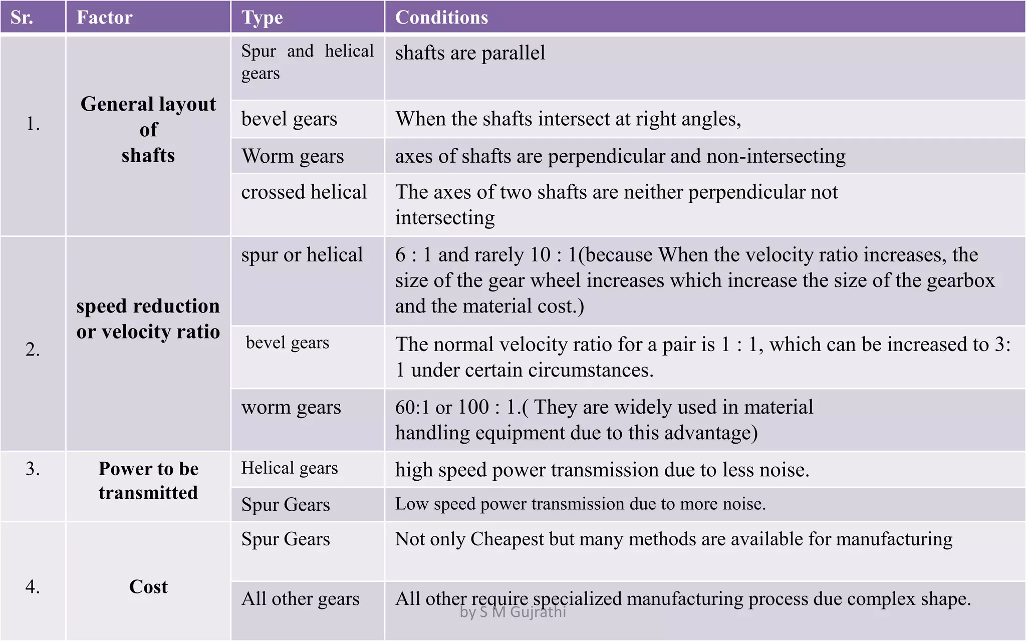
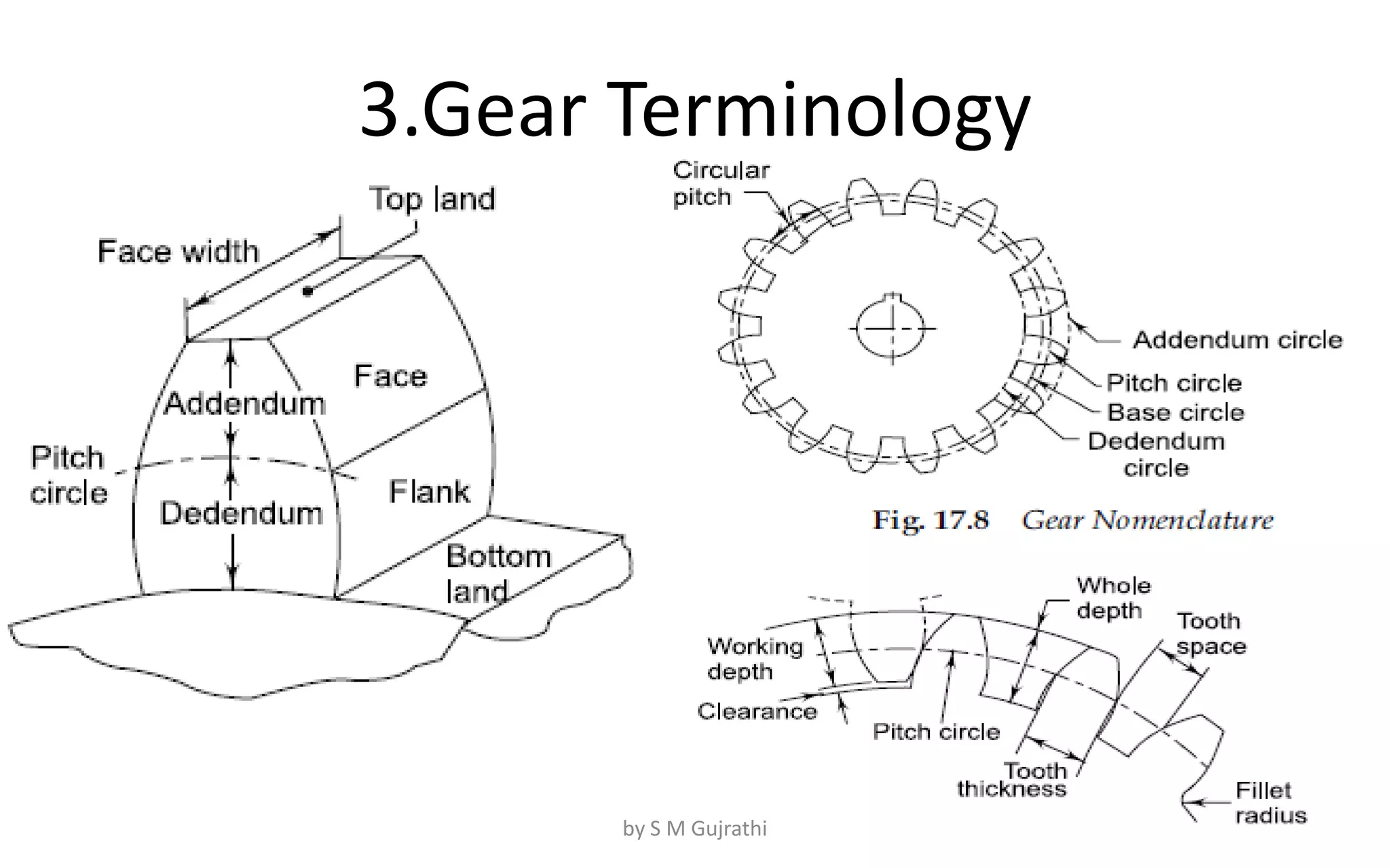
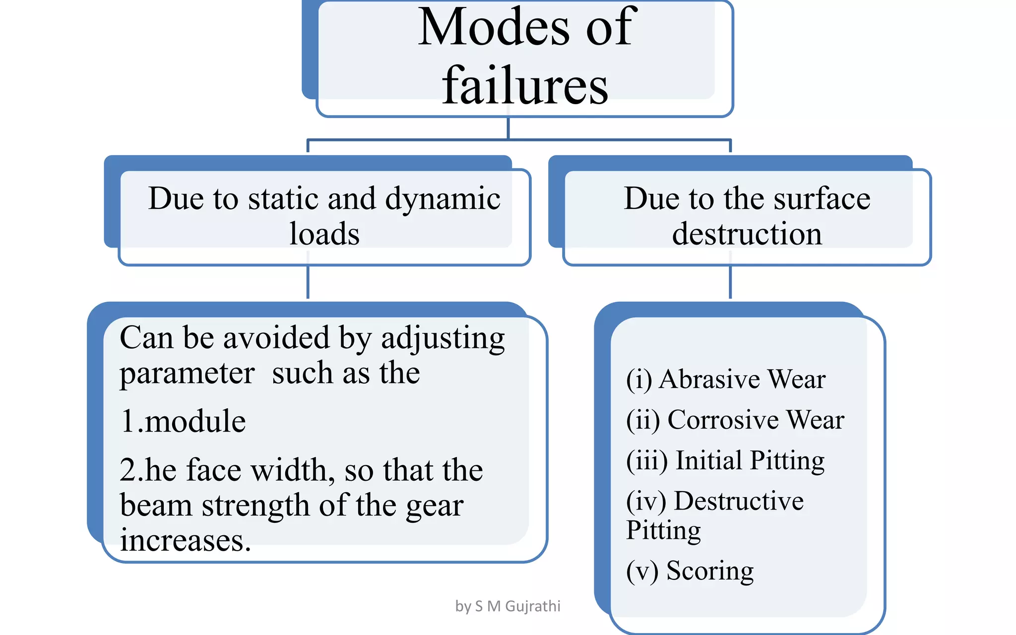
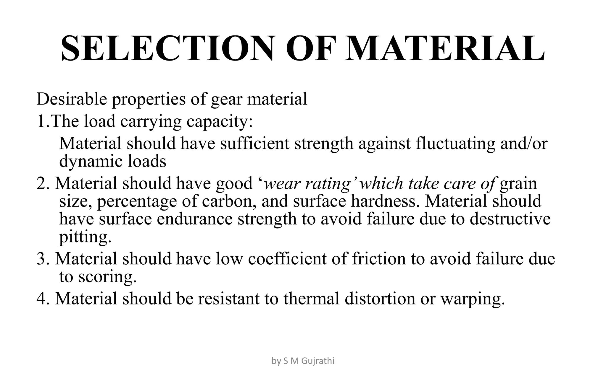
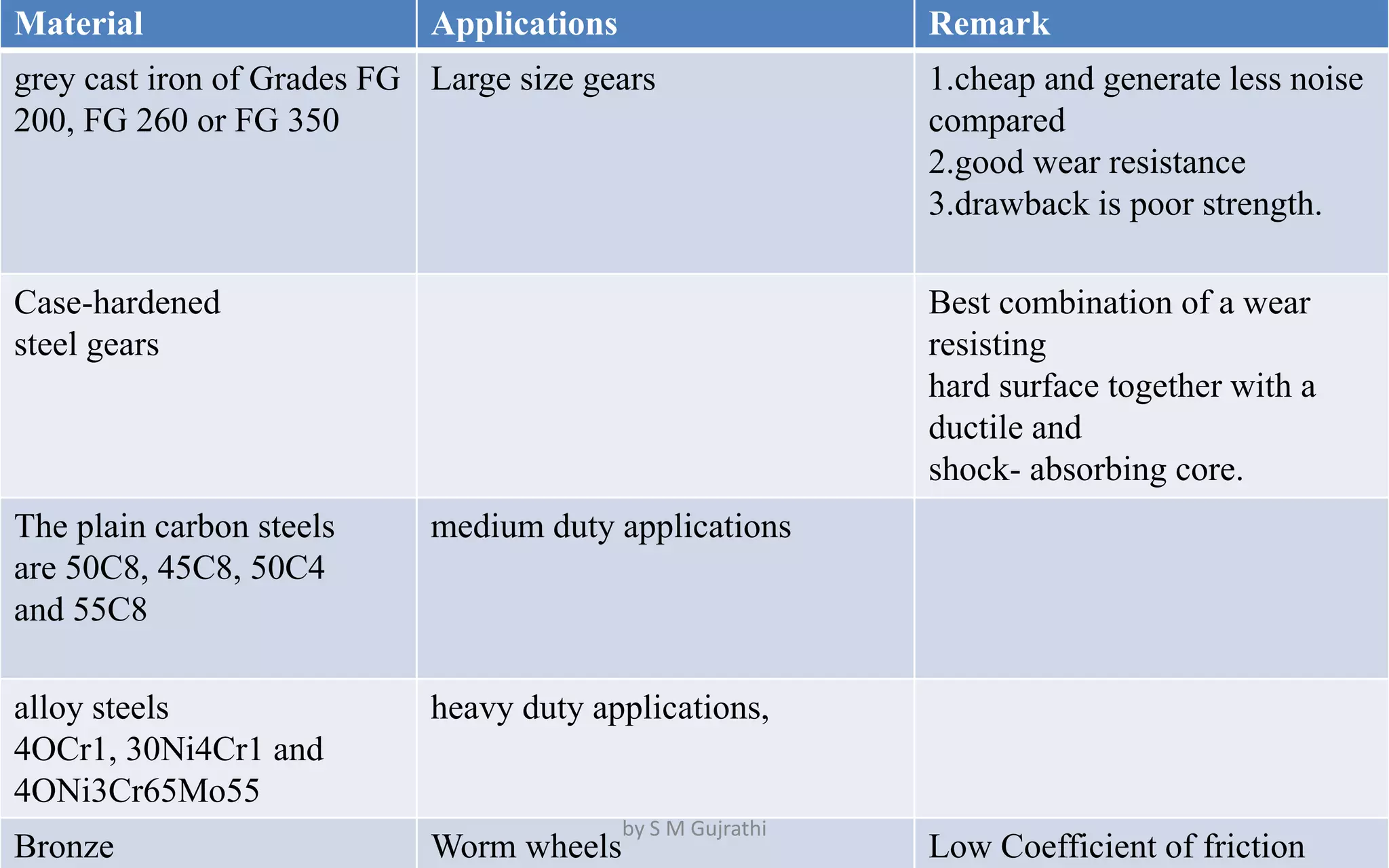
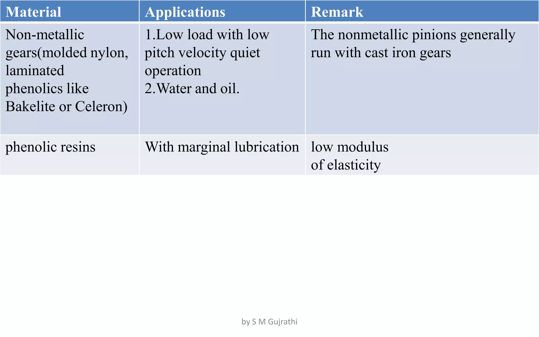
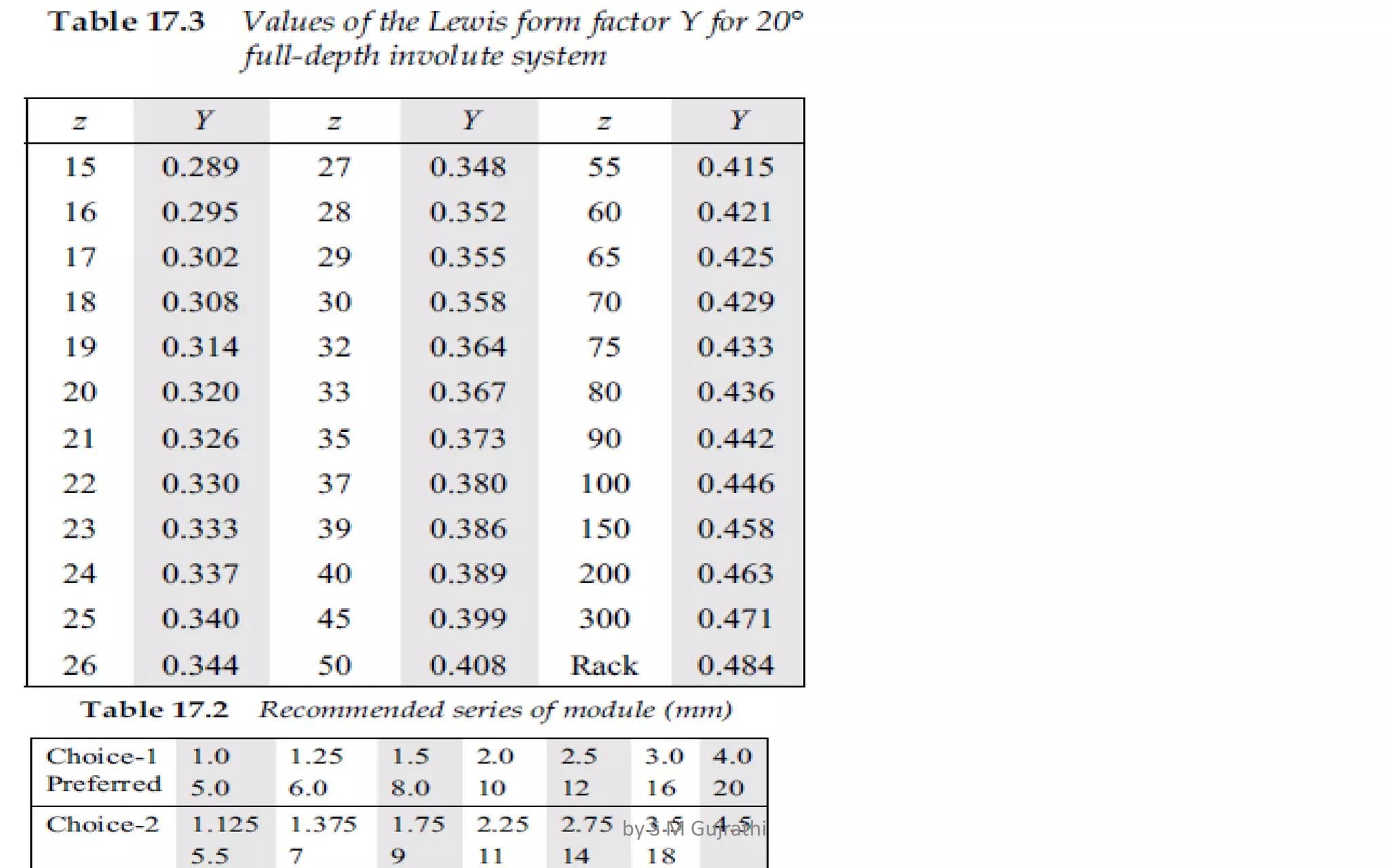
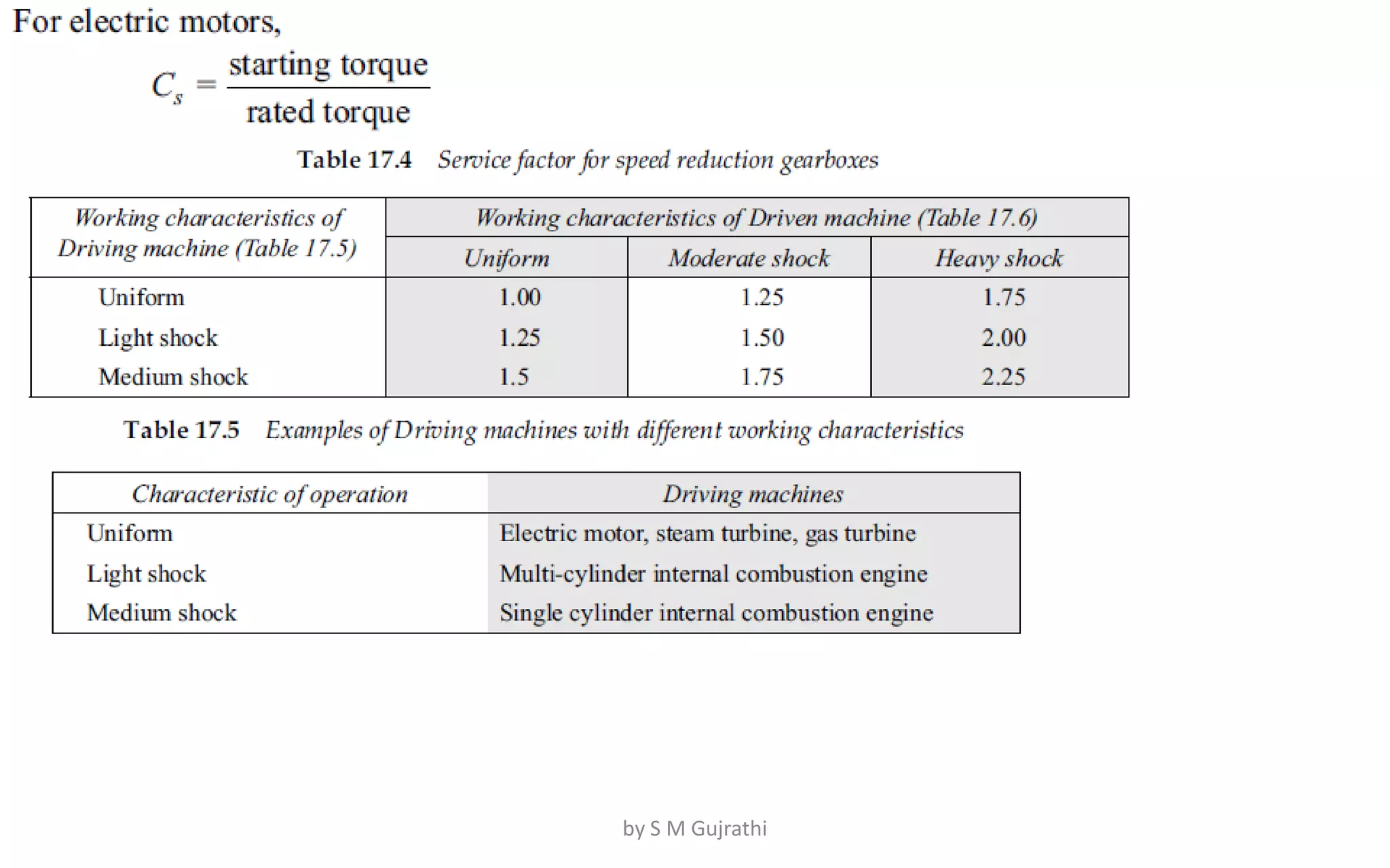
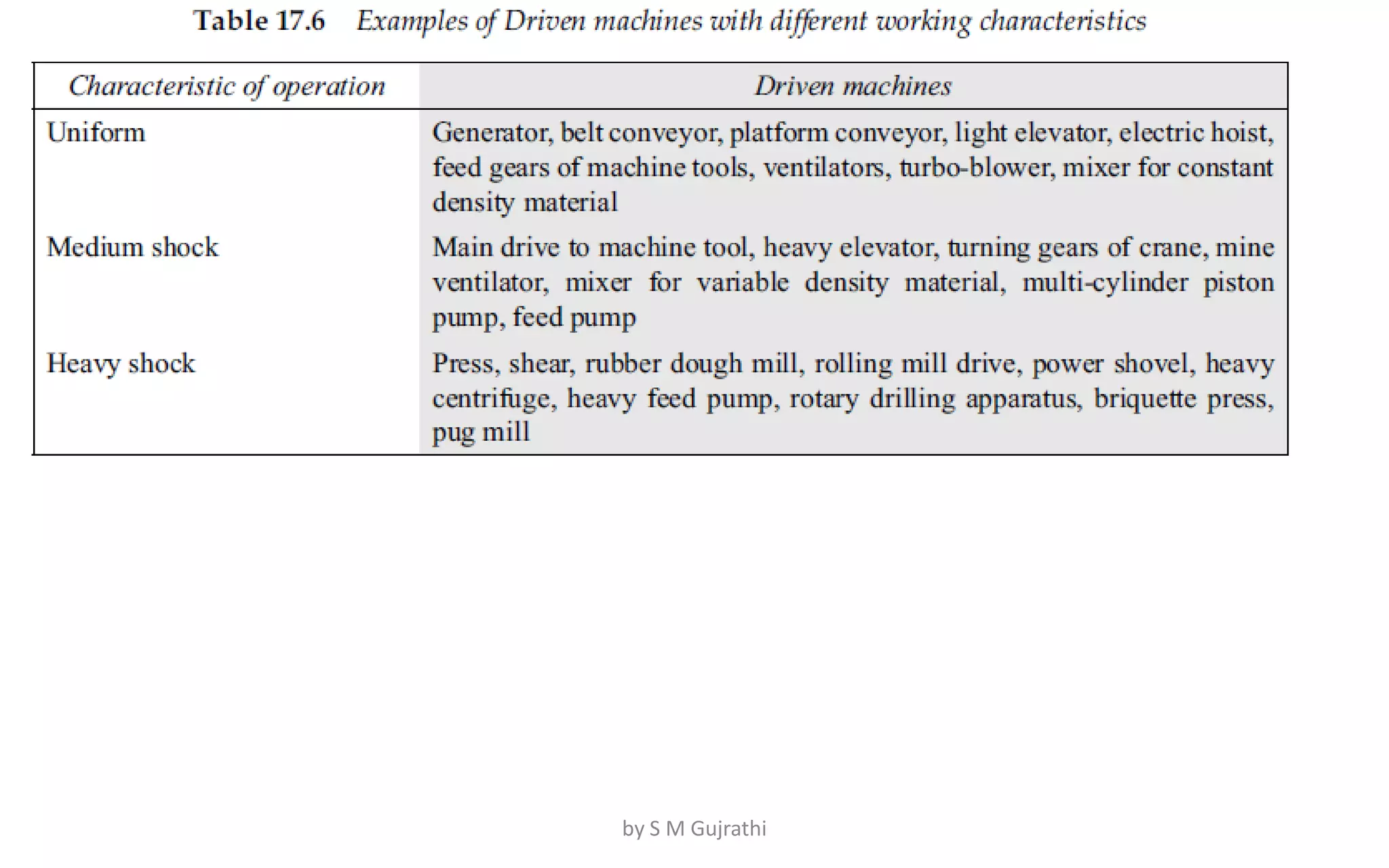
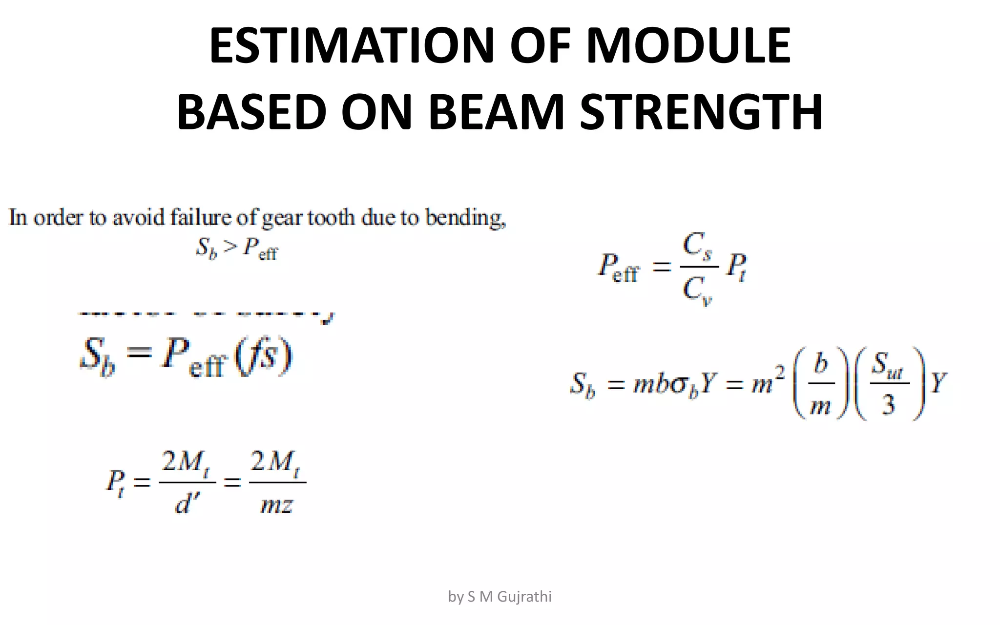
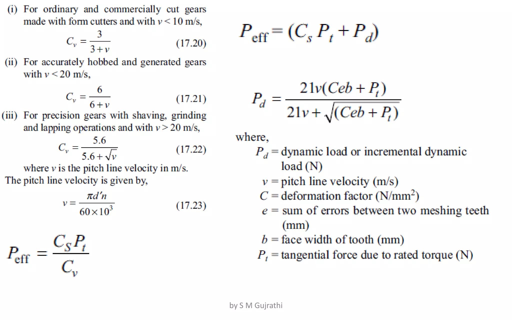
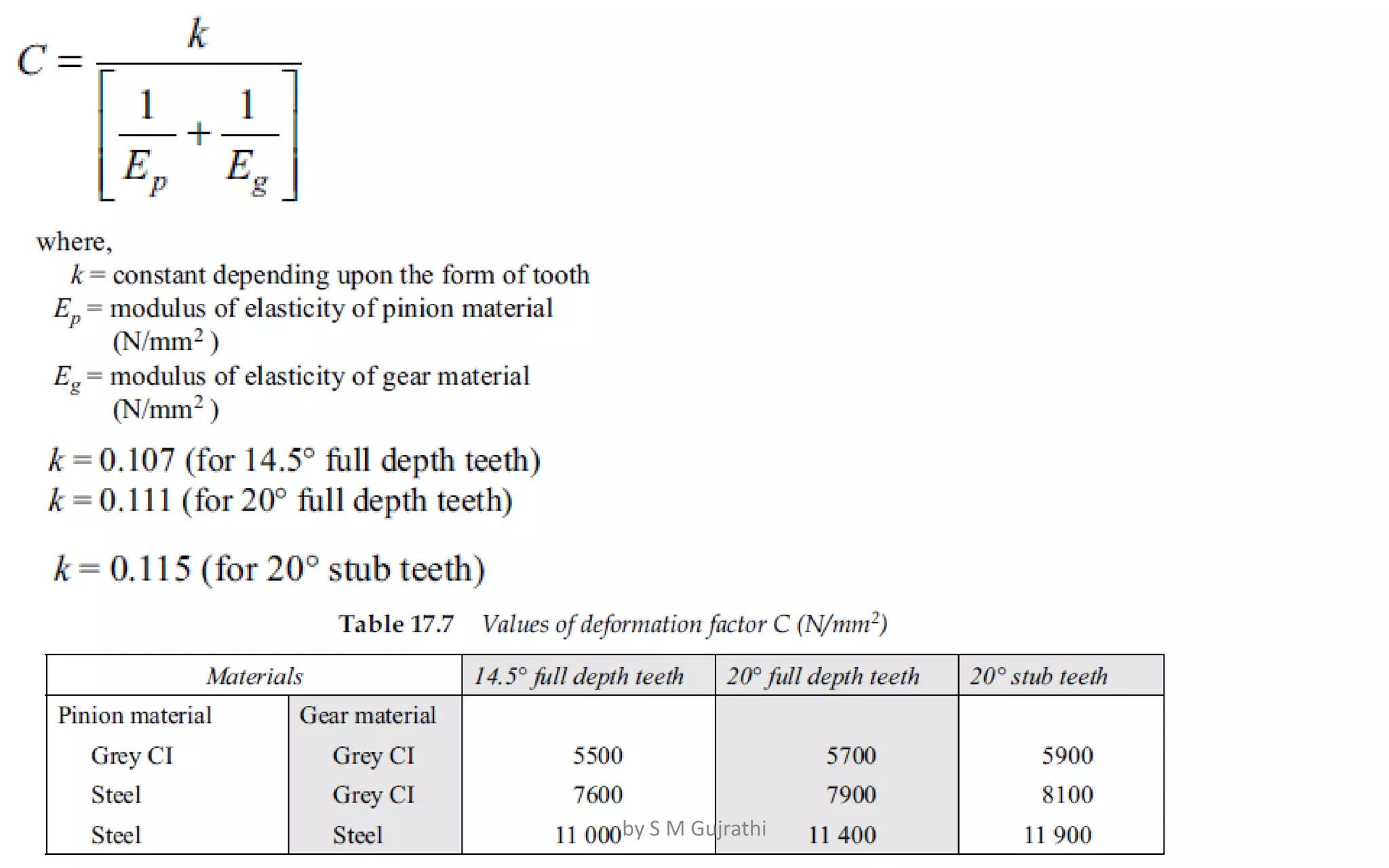
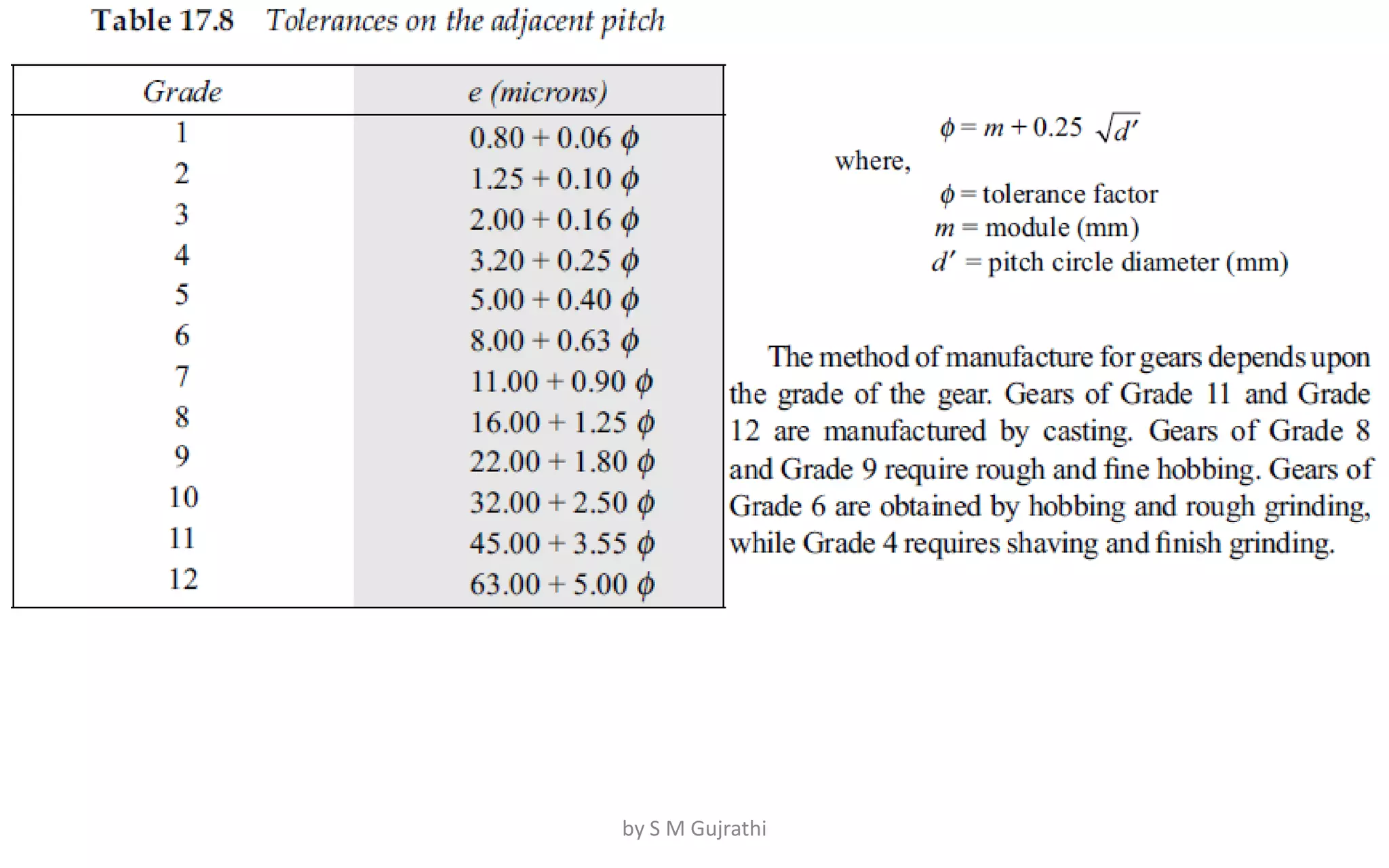
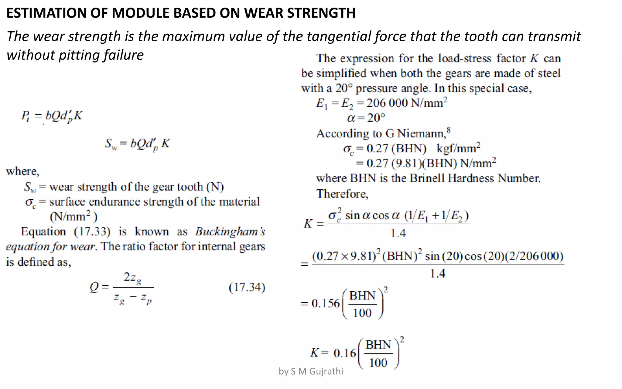
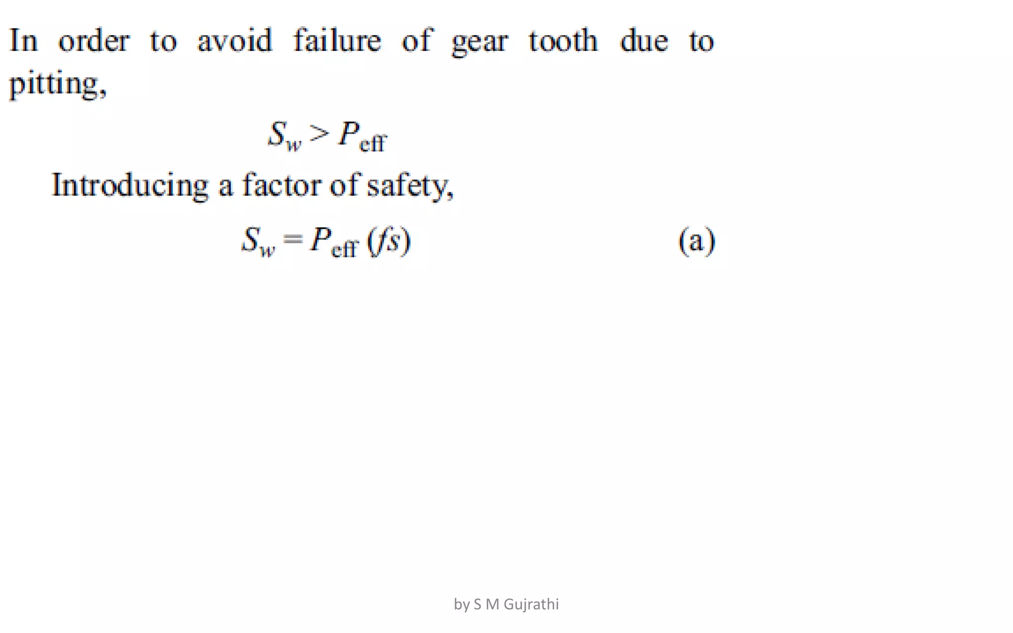
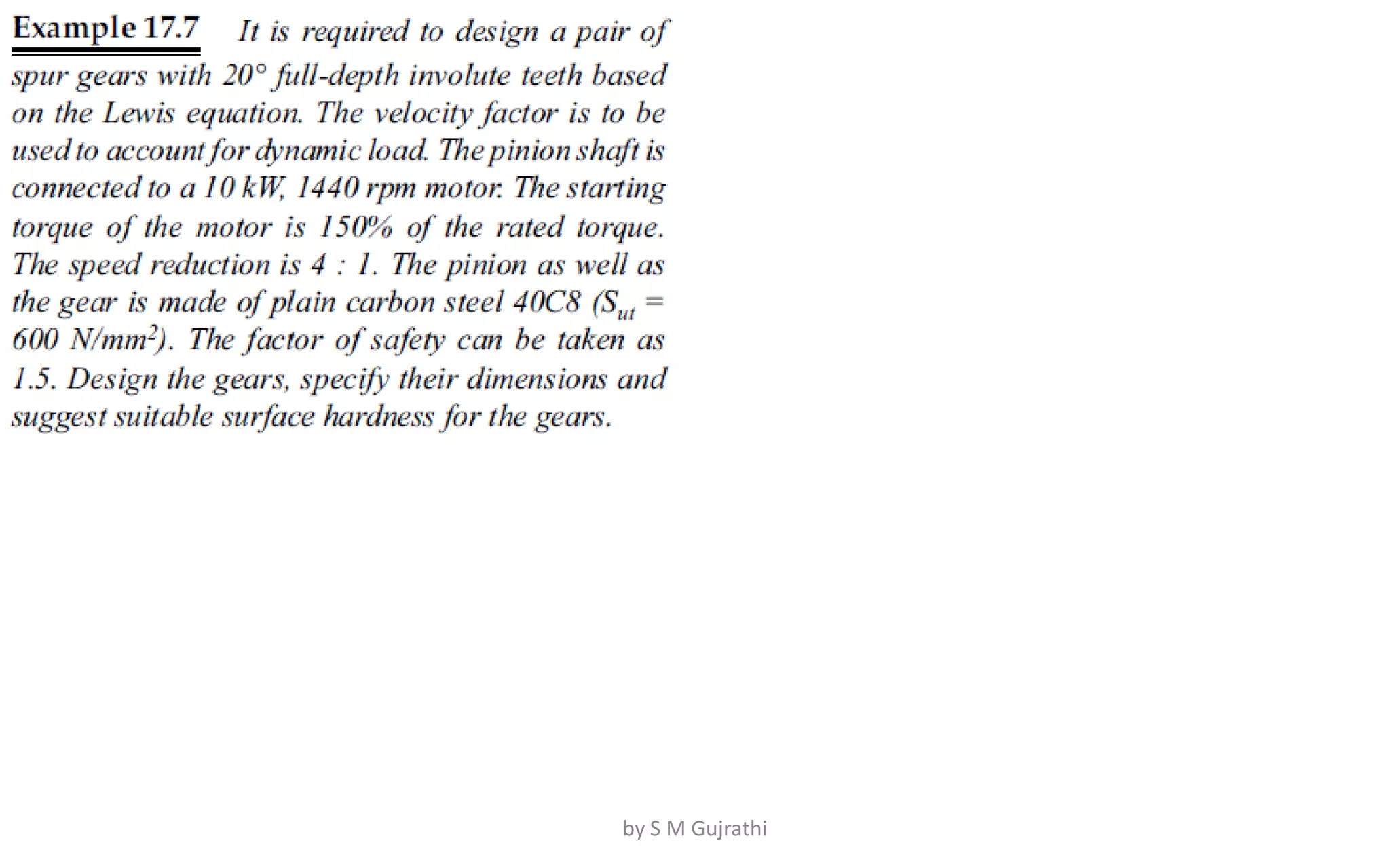
Subject : Machine Design-II
T.Y. Mechanical
Introduction to Machine Design-II
Ms. S M Gujrathi
Assistant Professor
E-mail : gujrathisonammech@sanjivani.org.in
by S M Gujrathi
Unit 1: Design of Spur Gears
A)Introduction to gears
Gear Selection,
material selection,
Basic modes of tooth failure,
Gear Lubrication Methods.
by S M Gujrathi
B)Spur Gears
Number of teeth and face width
Force analysis,
Beam strength (Lewis) equation,
Velocity factor,
Service factor,
Load concentration factor,
Effective load on gear,
 Wear strength(Buckingham’s)equation,
Estimation of module based on beam and wear strength,
Estimation of dynamic tooth load by velocity factor and
Buckingham’s equation.
by S M Gujrathi
C)Types of helical and Bevel gears,
Terminology,
Virtual number of teeth,
force analysis of Helical and Straight Bevel Gear.
Design of Helical and Straight Bevel Gear based on
Beam Strength,
Wear strength and estimation of effective load based
on Velocity factor (Barth factor) and Buckingham’s
equation.
Mountings of Bevel Gear. (No numerical on force
analysis of helical & Bevel Gear)
by S M Gujrathi
1.Introduction
• A mechanical drive is defined as a mechanism, which is
intended to transmit mechanical power over a certain distance,
usually involving a change in speed and torque.
1.Generally prime mover rotates at high speed and machines
requires low speed but high torque.
Eg. Crane drum. the motor runs at 1440 rpm while the speed
of the rope drum is as low as 20 rpm.
2. In certain machines, variable speeds are required for the
operation, whereas the prime mover runs at constant speed.
Eg. Lathe machine
3. Standard electric motors are designed for uniform rotary
motion. However, in some machines like shaper or planer,
linear motions with varying velocities are required.
by S M Gujrathi
1.1Classification of Drives
Mechanical Drives
Power transmission
by Friction
Ex.?
Power transmission
by Engagement
Ex.?
by S M Gujrathi
1.2 The selection of a proper
mechanical drive
Depends upon:
1. centre distance,
2. velocity ratio,
3. shifting arrangement,
4. maintenance considerations
5. cost.
General guidelines:
by S M Gujrathi
Sr. Factor Type Conditions
1. Center Distance
1.Flat belts and roller
chains
are suitable for long centre distances.
2. V-belts have comparatively short centre distances
2.Gear
drives
have the smallest centre distance between two shafts
2. Speed Ratio
1.flat belt drives
not recommended where constant speed is desirable.(Due to slipping
condition)
2. Chain drives
not recommended where constant speed is desirable.(Due to polygonal
effect.)
3.Gear drives are preferred in applications which require constant speed.
3.
Shifting
mechanism
1.Flat belts
with relatively long centre distances can be shifted from tight to loose
pulleys.
2.V-belts/chain drives it is not possible to use the shifting mechanism.
3. Spur gears can be shifted on splined shaft
4. Maintenance
1. belt drives
Maintenance of is relatively simple. It usually consists of periodic
adjustment of centre distance in order to compensate the stretch of the belt
2.Chain and gear
drives
lubrication is an important consideration in maintenance.
by S M Gujrathi
2. GEAR DRIVES
• Gears are defined as toothed wheels, which transmit power and
motion from one shaft to another by means of successive
engagement of teeth.
• Advantages over chain and belt drives:
(i)Velocity ratio remains constant because of a positive drive .
(ii) Compact in construction due to less CD.
(iii) It can transmit very large power, which is beyond the range of
belt or chain drives.
(iv) It can transmit motion at very low velocity, which is not possible
with the belt drives.
(v) The efficiency of gear drives is very high, even up to 99 percent in
case of spur gears.
(vi) A provision can be made in the gearbox for gear shifting, thus
changing the velocity ratio over a wide range.
by S M Gujrathi
Disadvantages
• Gear drives are, however, costly and their
maintenance cost is also higher.
• The manufacturing processes for gears are
complicated and highly specialized.
• Gear drives require careful attention for
lubrication and cleanliness.
• They also require precise alignment of the shafts.
by S M Gujrathi
2.1 CLASSIFICATION OF GEARS
Gear
by S M Gujrathi
Gears
Parallel shaft
axes gear
1.Spur gear
2.Helical gears
3.Herringbone
4.Rack and pinion
5.Internal Gears
Intersecting shaft
axes gears
Bevel Gears
Non Intersecting
and perpendicular
shafts axes
Worm Gears
Non Parallel and
non perpendicular
shaft axes gears
Spiral Gears
by S M Gujrathi
by S M Gujrathi
by S M Gujrathi
Herringbone gear box
by S M Gujrathi
Rack and Pinion
by S M Gujrathi
Internal Gears
by S M Gujrathi
Intersecting Shaft Axes Gear
i)Bevel Gear:
by S M Gujrathi
Non-Intersecting and perpendicular
axis gears
by S M Gujrathi
2.2SELECTION OF TYPE OF
GEARS
by S M Gujrathi
Sr. Factor Type Conditions
1.
General layout
of
shafts
Spur and helical
gears
shafts are parallel
bevel gears When the shafts intersect at right angles,
Worm gears axes of shafts are perpendicular and non-intersecting
crossed helical The axes of two shafts are neither perpendicular not
intersecting
2.
speed reduction
or velocity ratio
spur or helical 6 : 1 and rarely 10 : 1(because When the velocity ratio increases, the
size of the gear wheel increases which increase the size of the gearbox
and the material cost.)
bevel gears The normal velocity ratio for a pair is 1 : 1, which can be increased to 3:
1 under certain circumstances.
worm gears 60:1 or 100 : 1.( They are widely used in material
handling equipment due to this advantage)
3. Power to be
transmitted
Helical gears high speed power transmission due to less noise.
Spur Gears Low speed power transmission due to more noise.
4. Cost
Spur Gears Not only Cheapest but many methods are available for manufacturing
All other gears All other require specialized manufacturing process due complex shape.
by S M Gujrathi
3.Gear Terminology
by S M Gujrathi
(1) Pinion A pinion is the smaller of the two mating gears.
(2) Gear A gear is the larger of the two mating gears.
(3) Velocity Ratio (i) Velocity ratio is the ratio of angular velocity of the driving
gear(pinion) to the angular velocity of the driven gear(gear). It is also called
the speed ratio.
i = wp /wg
(4) Transmission Ratio (i) The transmission ratio (i’) is the ratio of the angular
speed of the first driving gear to the angular speed of the last driven gear in a
gear train.
(5) Pitch Surface The pitch surfaces of the gears are imaginary planes,
cylinders or cones that roll together without slipping.
(6) Pitch Circle The pitch circle is the curve of intersection of the pitch surface
of revolution and the plane of rotation.
(7) Pitch Circle Diameter The pitch circle diameter is the diameter of the pitch
circle.(pitch diameter) by S M Gujrathi
(7) Pitch Point: The pitch point is a point on the line of centres of two gears at
which two pitch circles of mating gears are tangent to each other.
(8) Top land The top land is the surface of the top of the gear tooth.
(9) Bottom land The bottom land is the surface of the gear between the flanks
of adjacent teeth.
(10) Addendum Circle The addendum circle is an imaginary circle that borders
the tops of gear teeth in the cross section.
(11) Addendum (ha) The addendum (ha) is the radial distance between the
pitch and the addendum circles. Addendum indicates the height of the tooth
above the pitch circle.
(12) Dedendum Circle The dedendum circle is an imaginary circle that borders
the bottom of spaces between teeth in the cross section. It is also called root
circle.
(13) Dedendum (hf) The dedendum (hf) is the radial distance between pitch and
the dedendum circles. The dedendum indicates the depth of the tooth below
the pitch circle.
by S M Gujrathi
(14)Clearance (c) The clearance is the amount by
which the dedendum of a given gear exceeds the
addendum of its mating tooth.
(15) Face of Tooth The surface of the gear tooth
between the pitch cylinder and the addendum
cylinder is called the face of tooth.
(16) Flank of Tooth The surface of the gear tooth
between the pitch cylinder and the root cylinder is
called fl ank of the tooth.
(17) Face Width (b) Face width is the width of the
tooth measured parallel to the axis.
by S M Gujrathi
(18)Centre Distance The centre distance is the
distance between centres of pitch circles of
mating gears. It is also the distance between
centres of base circles of mating gears.
(19) Pressure Angle The pressure angle is the
angle which the line of action makes with the
common tangent to the pitch circles. The
pressure angle is also called the angle of
obliquity. It is denoted by alpha.
(20) Contact Ratio (mp) The number of pairs of
teeth that are simultaneously engaged is called
contact ratio.
by S M Gujrathi
Circular Pitch The circular pitch (p) is the distance measured
along the pitch circle between two similar points on
adjacent teeth. Therefore,
Diametral Pitch The diametral pitch (P) is the ratio of the
number of teeth to the pitch circle diameter. Therefore,
Module The module (m) is defined as the inverse of the
diametral pitch. Therefore,
Variation of no. of teeth wrt module
by S M Gujrathi
by S M Gujrathi
Check your understanding:
1.If 2 pair of teeth is in contact with each other then
contact ratio is………
2. …………..is the amount by which the dedendum of a
given gear exceeds the addendum of its mating tooth.
3. A pair of spur gears consists of a 20 teeth pinion
meshing with a 120 teeth gear. The module is 4 mm.
Calculate:
(i) the centre distance=………
(ii) the pitch circle diameters of the pinion and the
gear=…………….
by S M Gujrathi
Modes of
failures
Due to static and dynamic
loads
Can be avoided by adjusting
parameter such as the
1.module
2.he face width, so that the
beam strength of the gear
increases.
Due to the surface
destruction
(i) Abrasive Wear
(ii) Corrosive Wear
(iii) Initial Pitting
(iv) Destructive
Pitting
(v) Scoring
by S M Gujrathi
SELECTION OF MATERIAL
Desirable properties of gear material
1.The load carrying capacity:
Material should have sufficient strength against fluctuating and/or
dynamic loads
2. Material should have good ‘wear rating’which take care of grain
size, percentage of carbon, and surface hardness. Material should
have surface endurance strength to avoid failure due to destructive
pitting.
3. Material should have low coefficient of friction to avoid failure due
to scoring.
4. Material should be resistant to thermal distortion or warping.
by S M Gujrathi
Material Applications Remark
grey cast iron of Grades FG
200, FG 260 or FG 350
Large size gears 1.cheap and generate less noise
compared
2.good wear resistance
3.drawback is poor strength.
Case-hardened
steel gears
Best combination of a wear
resisting
hard surface together with a
ductile and
shock- absorbing core.
The plain carbon steels
are 50C8, 45C8, 50C4
and 55C8
medium duty applications
alloy steels
4OCr1, 30Ni4Cr1 and
4ONi3Cr65Mo55
heavy duty applications,
Bronze Worm wheels Low Coefficient of friction
by S M Gujrathi
Material Applications Remark
Non-metallic
gears(molded nylon,
laminated
phenolics like
Bakelite or Celeron)
1.Low load with low
pitch velocity quiet
operation
2.Water and oil.
The nonmetallic pinions generally
run with cast iron gears
phenolic resins With marginal lubrication low modulus
of elasticity
by S M Gujrathi
by S M Gujrathi
by S M Gujrathi
by S M Gujrathi
ESTIMATION OF MODULE
BASED ON BEAM STRENGTH
by S M Gujrathi
by S M Gujrathi
by S M Gujrathi
by S M Gujrathi
ESTIMATION OF MODULE BASED ON WEAR STRENGTH
The wear strength is the maximum value of the tangential force that the tooth can transmit
without pitting failure
by S M Gujrathi
by S M Gujrathi
by S M Gujrathi

Unit 1 - Design of spur Gear Student copy.pdf

  • 1.
    Subject : MachineDesign-II T.Y. Mechanical Introduction to Machine Design-II Ms. S M Gujrathi Assistant Professor E-mail : gujrathisonammech@sanjivani.org.in by S M Gujrathi
  • 2.
    Unit 1: Designof Spur Gears A)Introduction to gears Gear Selection, material selection, Basic modes of tooth failure, Gear Lubrication Methods. by S M Gujrathi
  • 3.
    B)Spur Gears Number ofteeth and face width Force analysis, Beam strength (Lewis) equation, Velocity factor, Service factor, Load concentration factor, Effective load on gear,  Wear strength(Buckingham’s)equation, Estimation of module based on beam and wear strength, Estimation of dynamic tooth load by velocity factor and Buckingham’s equation. by S M Gujrathi
  • 4.
    C)Types of helicaland Bevel gears, Terminology, Virtual number of teeth, force analysis of Helical and Straight Bevel Gear. Design of Helical and Straight Bevel Gear based on Beam Strength, Wear strength and estimation of effective load based on Velocity factor (Barth factor) and Buckingham’s equation. Mountings of Bevel Gear. (No numerical on force analysis of helical & Bevel Gear) by S M Gujrathi
  • 5.
    1.Introduction • A mechanicaldrive is defined as a mechanism, which is intended to transmit mechanical power over a certain distance, usually involving a change in speed and torque. 1.Generally prime mover rotates at high speed and machines requires low speed but high torque. Eg. Crane drum. the motor runs at 1440 rpm while the speed of the rope drum is as low as 20 rpm. 2. In certain machines, variable speeds are required for the operation, whereas the prime mover runs at constant speed. Eg. Lathe machine 3. Standard electric motors are designed for uniform rotary motion. However, in some machines like shaper or planer, linear motions with varying velocities are required. by S M Gujrathi
  • 6.
    1.1Classification of Drives MechanicalDrives Power transmission by Friction Ex.? Power transmission by Engagement Ex.? by S M Gujrathi
  • 7.
    1.2 The selectionof a proper mechanical drive Depends upon: 1. centre distance, 2. velocity ratio, 3. shifting arrangement, 4. maintenance considerations 5. cost. General guidelines: by S M Gujrathi
  • 8.
    Sr. Factor TypeConditions 1. Center Distance 1.Flat belts and roller chains are suitable for long centre distances. 2. V-belts have comparatively short centre distances 2.Gear drives have the smallest centre distance between two shafts 2. Speed Ratio 1.flat belt drives not recommended where constant speed is desirable.(Due to slipping condition) 2. Chain drives not recommended where constant speed is desirable.(Due to polygonal effect.) 3.Gear drives are preferred in applications which require constant speed. 3. Shifting mechanism 1.Flat belts with relatively long centre distances can be shifted from tight to loose pulleys. 2.V-belts/chain drives it is not possible to use the shifting mechanism. 3. Spur gears can be shifted on splined shaft 4. Maintenance 1. belt drives Maintenance of is relatively simple. It usually consists of periodic adjustment of centre distance in order to compensate the stretch of the belt 2.Chain and gear drives lubrication is an important consideration in maintenance. by S M Gujrathi
  • 9.
    2. GEAR DRIVES •Gears are defined as toothed wheels, which transmit power and motion from one shaft to another by means of successive engagement of teeth. • Advantages over chain and belt drives: (i)Velocity ratio remains constant because of a positive drive . (ii) Compact in construction due to less CD. (iii) It can transmit very large power, which is beyond the range of belt or chain drives. (iv) It can transmit motion at very low velocity, which is not possible with the belt drives. (v) The efficiency of gear drives is very high, even up to 99 percent in case of spur gears. (vi) A provision can be made in the gearbox for gear shifting, thus changing the velocity ratio over a wide range. by S M Gujrathi
  • 10.
    Disadvantages • Gear drivesare, however, costly and their maintenance cost is also higher. • The manufacturing processes for gears are complicated and highly specialized. • Gear drives require careful attention for lubrication and cleanliness. • They also require precise alignment of the shafts. by S M Gujrathi
  • 11.
    2.1 CLASSIFICATION OFGEARS Gear by S M Gujrathi
  • 12.
    Gears Parallel shaft axes gear 1.Spurgear 2.Helical gears 3.Herringbone 4.Rack and pinion 5.Internal Gears Intersecting shaft axes gears Bevel Gears Non Intersecting and perpendicular shafts axes Worm Gears Non Parallel and non perpendicular shaft axes gears Spiral Gears by S M Gujrathi
  • 13.
    by S MGujrathi
  • 14.
    by S MGujrathi
  • 15.
  • 16.
    Rack and Pinion byS M Gujrathi
  • 17.
  • 18.
    Intersecting Shaft AxesGear i)Bevel Gear: by S M Gujrathi
  • 19.
  • 20.
    2.2SELECTION OF TYPEOF GEARS by S M Gujrathi
  • 21.
    Sr. Factor TypeConditions 1. General layout of shafts Spur and helical gears shafts are parallel bevel gears When the shafts intersect at right angles, Worm gears axes of shafts are perpendicular and non-intersecting crossed helical The axes of two shafts are neither perpendicular not intersecting 2. speed reduction or velocity ratio spur or helical 6 : 1 and rarely 10 : 1(because When the velocity ratio increases, the size of the gear wheel increases which increase the size of the gearbox and the material cost.) bevel gears The normal velocity ratio for a pair is 1 : 1, which can be increased to 3: 1 under certain circumstances. worm gears 60:1 or 100 : 1.( They are widely used in material handling equipment due to this advantage) 3. Power to be transmitted Helical gears high speed power transmission due to less noise. Spur Gears Low speed power transmission due to more noise. 4. Cost Spur Gears Not only Cheapest but many methods are available for manufacturing All other gears All other require specialized manufacturing process due complex shape. by S M Gujrathi
  • 22.
  • 23.
    (1) Pinion Apinion is the smaller of the two mating gears. (2) Gear A gear is the larger of the two mating gears. (3) Velocity Ratio (i) Velocity ratio is the ratio of angular velocity of the driving gear(pinion) to the angular velocity of the driven gear(gear). It is also called the speed ratio. i = wp /wg (4) Transmission Ratio (i) The transmission ratio (i’) is the ratio of the angular speed of the first driving gear to the angular speed of the last driven gear in a gear train. (5) Pitch Surface The pitch surfaces of the gears are imaginary planes, cylinders or cones that roll together without slipping. (6) Pitch Circle The pitch circle is the curve of intersection of the pitch surface of revolution and the plane of rotation. (7) Pitch Circle Diameter The pitch circle diameter is the diameter of the pitch circle.(pitch diameter) by S M Gujrathi
  • 24.
    (7) Pitch Point:The pitch point is a point on the line of centres of two gears at which two pitch circles of mating gears are tangent to each other. (8) Top land The top land is the surface of the top of the gear tooth. (9) Bottom land The bottom land is the surface of the gear between the flanks of adjacent teeth. (10) Addendum Circle The addendum circle is an imaginary circle that borders the tops of gear teeth in the cross section. (11) Addendum (ha) The addendum (ha) is the radial distance between the pitch and the addendum circles. Addendum indicates the height of the tooth above the pitch circle. (12) Dedendum Circle The dedendum circle is an imaginary circle that borders the bottom of spaces between teeth in the cross section. It is also called root circle. (13) Dedendum (hf) The dedendum (hf) is the radial distance between pitch and the dedendum circles. The dedendum indicates the depth of the tooth below the pitch circle. by S M Gujrathi
  • 25.
    (14)Clearance (c) Theclearance is the amount by which the dedendum of a given gear exceeds the addendum of its mating tooth. (15) Face of Tooth The surface of the gear tooth between the pitch cylinder and the addendum cylinder is called the face of tooth. (16) Flank of Tooth The surface of the gear tooth between the pitch cylinder and the root cylinder is called fl ank of the tooth. (17) Face Width (b) Face width is the width of the tooth measured parallel to the axis. by S M Gujrathi
  • 26.
    (18)Centre Distance Thecentre distance is the distance between centres of pitch circles of mating gears. It is also the distance between centres of base circles of mating gears. (19) Pressure Angle The pressure angle is the angle which the line of action makes with the common tangent to the pitch circles. The pressure angle is also called the angle of obliquity. It is denoted by alpha. (20) Contact Ratio (mp) The number of pairs of teeth that are simultaneously engaged is called contact ratio. by S M Gujrathi
  • 27.
    Circular Pitch Thecircular pitch (p) is the distance measured along the pitch circle between two similar points on adjacent teeth. Therefore, Diametral Pitch The diametral pitch (P) is the ratio of the number of teeth to the pitch circle diameter. Therefore, Module The module (m) is defined as the inverse of the diametral pitch. Therefore, Variation of no. of teeth wrt module by S M Gujrathi
  • 28.
    by S MGujrathi
  • 29.
    Check your understanding: 1.If2 pair of teeth is in contact with each other then contact ratio is……… 2. …………..is the amount by which the dedendum of a given gear exceeds the addendum of its mating tooth. 3. A pair of spur gears consists of a 20 teeth pinion meshing with a 120 teeth gear. The module is 4 mm. Calculate: (i) the centre distance=……… (ii) the pitch circle diameters of the pinion and the gear=……………. by S M Gujrathi
  • 30.
    Modes of failures Due tostatic and dynamic loads Can be avoided by adjusting parameter such as the 1.module 2.he face width, so that the beam strength of the gear increases. Due to the surface destruction (i) Abrasive Wear (ii) Corrosive Wear (iii) Initial Pitting (iv) Destructive Pitting (v) Scoring by S M Gujrathi
  • 31.
    SELECTION OF MATERIAL Desirableproperties of gear material 1.The load carrying capacity: Material should have sufficient strength against fluctuating and/or dynamic loads 2. Material should have good ‘wear rating’which take care of grain size, percentage of carbon, and surface hardness. Material should have surface endurance strength to avoid failure due to destructive pitting. 3. Material should have low coefficient of friction to avoid failure due to scoring. 4. Material should be resistant to thermal distortion or warping. by S M Gujrathi
  • 32.
    Material Applications Remark greycast iron of Grades FG 200, FG 260 or FG 350 Large size gears 1.cheap and generate less noise compared 2.good wear resistance 3.drawback is poor strength. Case-hardened steel gears Best combination of a wear resisting hard surface together with a ductile and shock- absorbing core. The plain carbon steels are 50C8, 45C8, 50C4 and 55C8 medium duty applications alloy steels 4OCr1, 30Ni4Cr1 and 4ONi3Cr65Mo55 heavy duty applications, Bronze Worm wheels Low Coefficient of friction by S M Gujrathi
  • 33.
    Material Applications Remark Non-metallic gears(moldednylon, laminated phenolics like Bakelite or Celeron) 1.Low load with low pitch velocity quiet operation 2.Water and oil. The nonmetallic pinions generally run with cast iron gears phenolic resins With marginal lubrication low modulus of elasticity by S M Gujrathi
  • 34.
    by S MGujrathi
  • 35.
    by S MGujrathi
  • 36.
    by S MGujrathi
  • 37.
    ESTIMATION OF MODULE BASEDON BEAM STRENGTH by S M Gujrathi
  • 38.
    by S MGujrathi
  • 39.
    by S MGujrathi
  • 40.
    by S MGujrathi
  • 41.
    ESTIMATION OF MODULEBASED ON WEAR STRENGTH The wear strength is the maximum value of the tangential force that the tooth can transmit without pitting failure by S M Gujrathi
  • 42.
    by S MGujrathi
  • 43.
    by S MGujrathi