Download to read offline


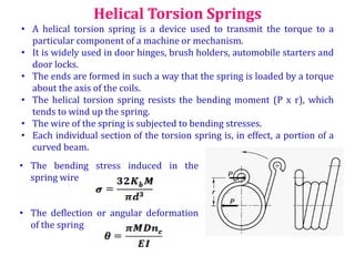
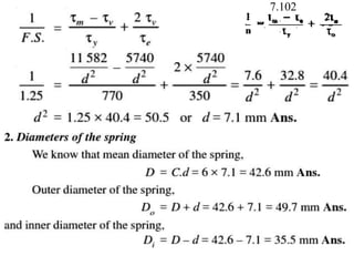
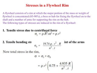
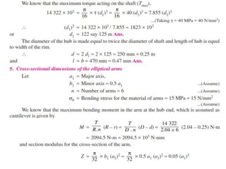
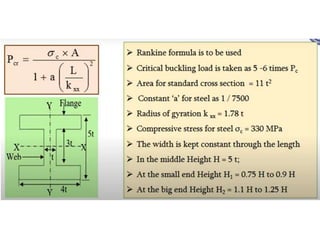
![Material for Helical Springs
Music wire is used for small springs.
Non-ferrous materials like phosphor bronze, beryllium copper, monel
metal, brass etc., may be used in special cases to increase fatigue
resistance, temperature resistance and corrosion resistance.
Table PSGDB 7.105 shows the values of allowable shear stress for various
materials used for springs.
The helical springs are either cold formed or hot formed depending upon
the size of the wire.
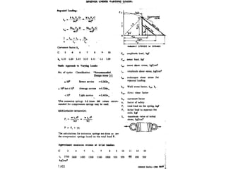
Static Approach to varying Loads
No. of cycles Classification
*Recommended
Design Stress [t]
> 106 Severe service 0.263su
>104 but <106 Average service 0.324su
<104 Light service 0.405su](https://image.slidesharecdn.com/unit4energystoringelementsandenginecomponents-221127154904-9401182b/85/UNIT-4-Energy-storing-elements-and-Engine-components-pptx-8-320.jpg)


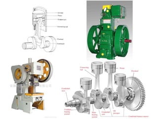
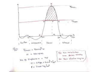
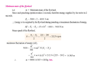
![• Assuming that both the springs are made of same material, then
the maximum shear stress induced in both the springs is
approximately same, i.e. τ1 = τ2
• If both the springs are effective throughout their working range,
then their free length and deflection are equal, i.e. y1 =y2
• The following relations are used for designing Concentric
springs.
• τ1 = τ2 < [τ]
• D1/d1 = D2/d2 =C
• P1/P2 =2(C/(C-2))
• d1< (D1-D2)/2
Concentric or Composite Springs](https://image.slidesharecdn.com/unit4energystoringelementsandenginecomponents-221127154904-9401182b/85/UNIT-4-Energy-storing-elements-and-Engine-components-pptx-26-320.jpg)


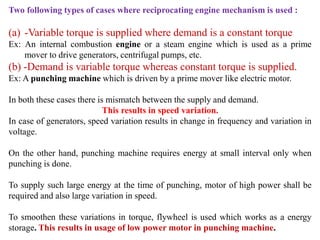


![[PSG (p.7.120)]](https://image.slidesharecdn.com/unit4energystoringelementsandenginecomponents-221127154904-9401182b/85/UNIT-4-Energy-storing-elements-and-Engine-components-pptx-95-320.jpg)


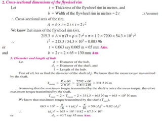


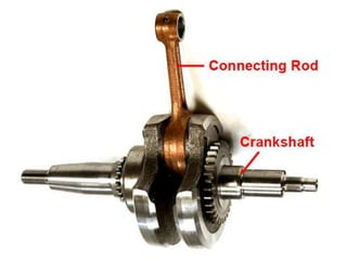


This document discusses various energy storing elements and engine components. It describes springs, including helical springs, leaf springs, Belleville springs, and concentric springs. It discusses the material, design, and stresses in helical springs. It also covers flywheels, connecting rods, and crankshafts as key engine components that help store and transmit energy within an engine.