Downloaded 15 times


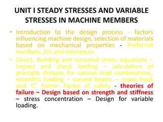
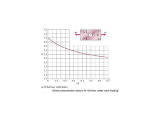
![ɪ section
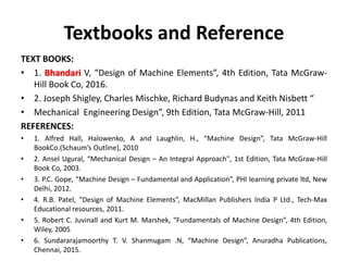
• Given that depth is 7t and width is 5t
• ɪ = ɪ1 - ɪ2
• = b1 h1
3 / 12 - 2 x b2 h2
3 / 12
• = [5t (7t)3 – 2 x 2t (5t)3 ]/12
• ɪ = 1125t4 / 12
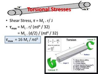
• Bending moment equation:
•
σb
𝑦
=
Mb
ɪ
• Where y = 3.5t (i.e., h/2)
7t
5t
1t
1t
5t
t](https://image.slidesharecdn.com/dme-unit1-221127154738-9d19fe6a/85/DME-Unit1-pptx-91-320.jpg)


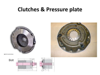
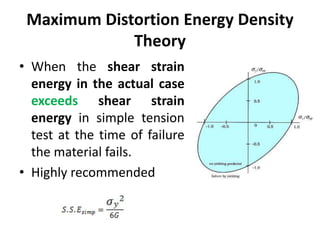
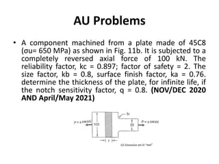
![h = 10mm; l = 3m = 3000mm; A = 600mm2
; l = 2 mm; E =200 x 103 N/mm2
Solution:
• E = l/ l E l/l =
• = 200 x 103 * 2 / 3000
• = 133.3 N/mm2
• = W/A [1 + 1 +
2ℎ𝐴𝐸
𝑊𝑙
]
• W = 6666.7 N](https://image.slidesharecdn.com/dme-unit1-221127154738-9d19fe6a/85/DME-Unit1-pptx-100-320.jpg)


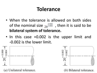
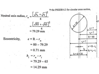
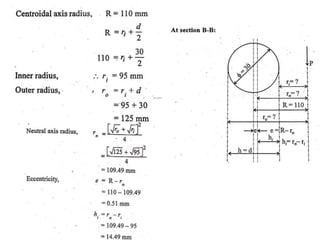
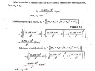
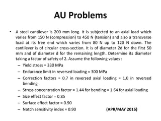
![Approach to Curved beam problems
• Step 1: Find Direct Stress d = P/A
• Step 2: Find the bending stress bi = M .h/a.e.r
(Mostly for Inner fibre) – Find out other
parameters [PSG DB – 6.2]
– Step 2.1 : Various Radius: R, ri, ro, rn,
– Step 2.2 : Eccentricity : e, hi
– Step 2.3 : Moment Mb
• Either Load, diameter or max stress has to be
found](https://image.slidesharecdn.com/dme-unit1-221127154738-9d19fe6a/85/DME-Unit1-pptx-141-320.jpg)


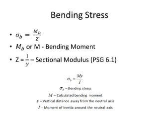
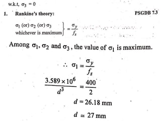
![Approach to Curved beam problems
• Step 1: Find Direct Stress d = P/A
• Step 2: Find the bending stress bi = M .h/a.e.r
(Mostly for Inner fibre) – Find out other
parameters [PSG DB – 6.2]
– Step 2.1 : Various Radius: R, ri, ro, rn,
– Step 2.2 : Eccentricity : e, hi
– Step 2.3 : Moment Mb
• Either Load, diameter or max stress has to be
found](https://image.slidesharecdn.com/dme-unit1-221127154738-9d19fe6a/85/DME-Unit1-pptx-164-320.jpg)


![Factors affecting Endurance limit
• Size factor (KS)
• Load Factor (KL)
• Surface Factor (Ksf)
• Reliability Factor (KR)
• Other factors/Miscellaneous factor such as
Temperature factor, impact factor, etc
• Fatigue stress concentration factor,
Kf = 1+q(Kt- 1) [Kt - Theoretical stress
concentration factor, q- notch sensitivity factor]](https://image.slidesharecdn.com/dme-unit1-221127154738-9d19fe6a/85/DME-Unit1-pptx-227-320.jpg)


![• For goodman’s equation:
1
𝑛
=
𝐾𝑡
𝐾𝑆𝑍. 𝐾𝑆𝐹
[
𝜎𝑚
𝜎𝑦
+
𝜎𝑎
𝜎−1
]](https://image.slidesharecdn.com/dme-unit1-221127154738-9d19fe6a/85/DME-Unit1-pptx-235-320.jpg)


The document discusses the contents of Unit 1 of the subject ME 8593-DESIGN OF MACHINE ELEMENTS. It includes an introduction to the design process and factors influencing machine design. It also discusses selection of materials based on mechanical properties, preferred numbers, fits and tolerances. Additionally, it covers direct, bending and torsional stress equations, impact and shock loading, calculation of principle stresses for various load combinations, eccentric loading, curved beams, crane hook and 'C' frame. The document also mentions factor of safety, theories of failure, design based on strength and stiffness, stress concentration and design for variable loading.


![Attack surfaces and attack tress[inform]](https://cdn.slidesharecdn.com/ss_thumbnails/lecture03-260108015941-a4dee53b-thumbnail.jpg?width=640&height=640&fit=bounds)


