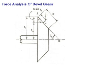
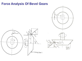
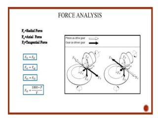
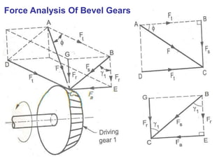
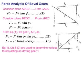
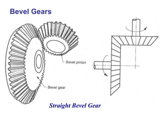
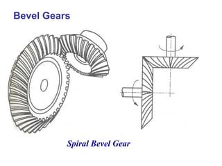
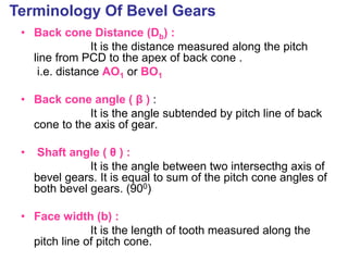
The document covers the theory and terminology related to bevel gears, including definitions of pitch cone angles, back cones, and shaft angles. It also discusses the geometrical relationships involving these angles and the force analysis for bevel gears during their operation. Key formulas for calculating gear ratios and forces acting on bevel gears are presented, highlighting the interactions between driving and driven gears.


![11
2
1
1
211
2
1
1
2
2
1
1
2
1
2
1
2
2
1
1
sincoscossinsin
].....[).........sin(sin
sinsin
sin
sin
)1(..........
sinsin
r
r
r
r
r
r
r
r
rr
OP
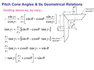
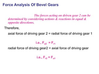
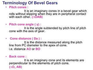
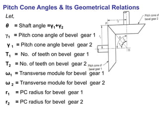
G = Gear ratio = T2/T1= r2/r1 = ω1/ ω2
Frm fig;
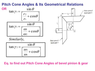
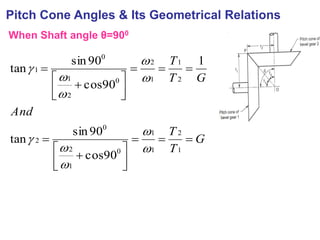
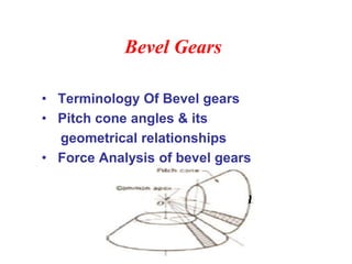
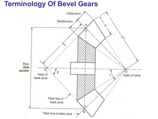
Pitch Cone Angles & Its Geometrical Relations](https://image.slidesharecdn.com/unitiibevelgears-200916072037/85/Unit-ii-bevel-gears-13-320.jpg)