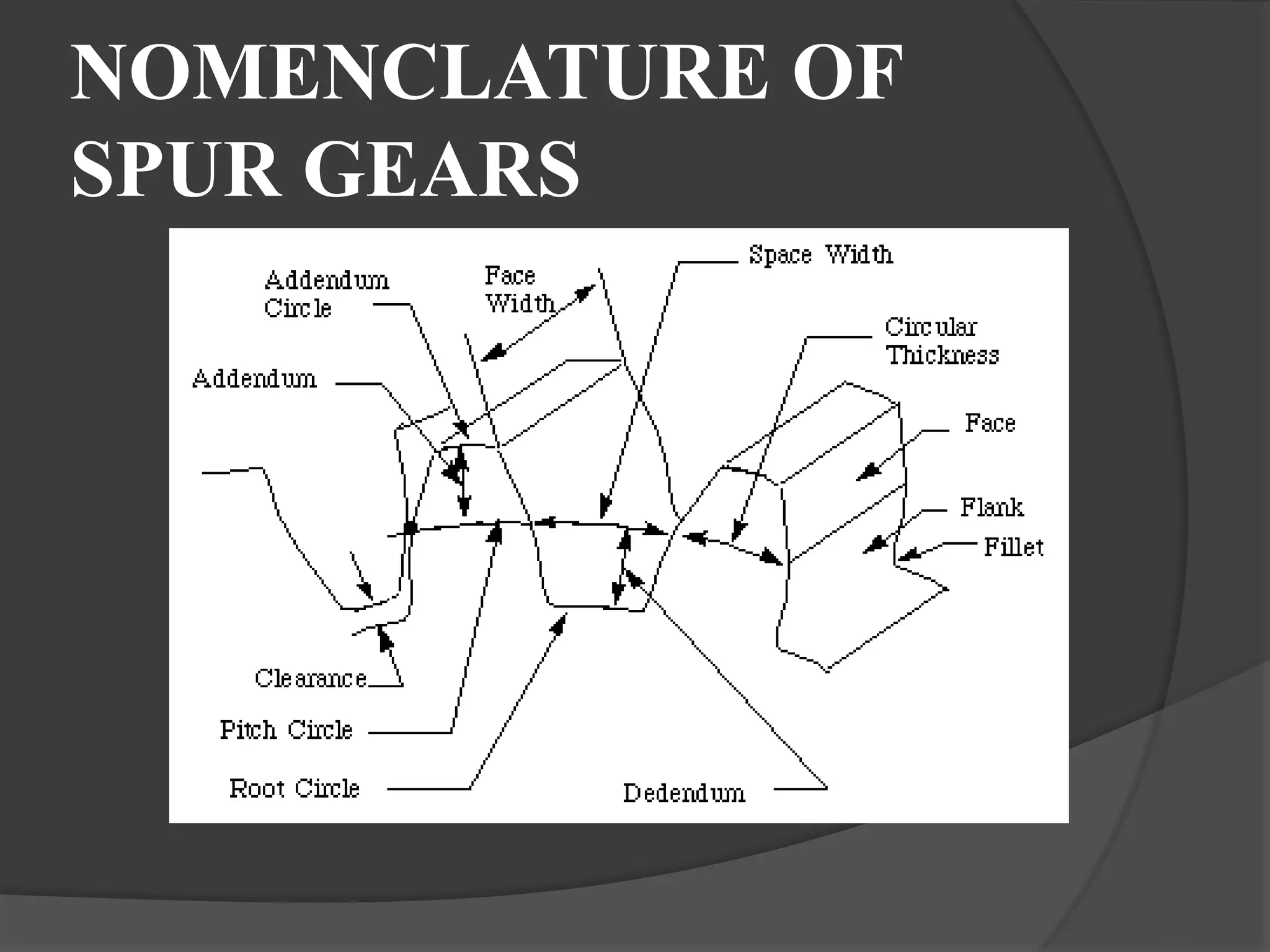
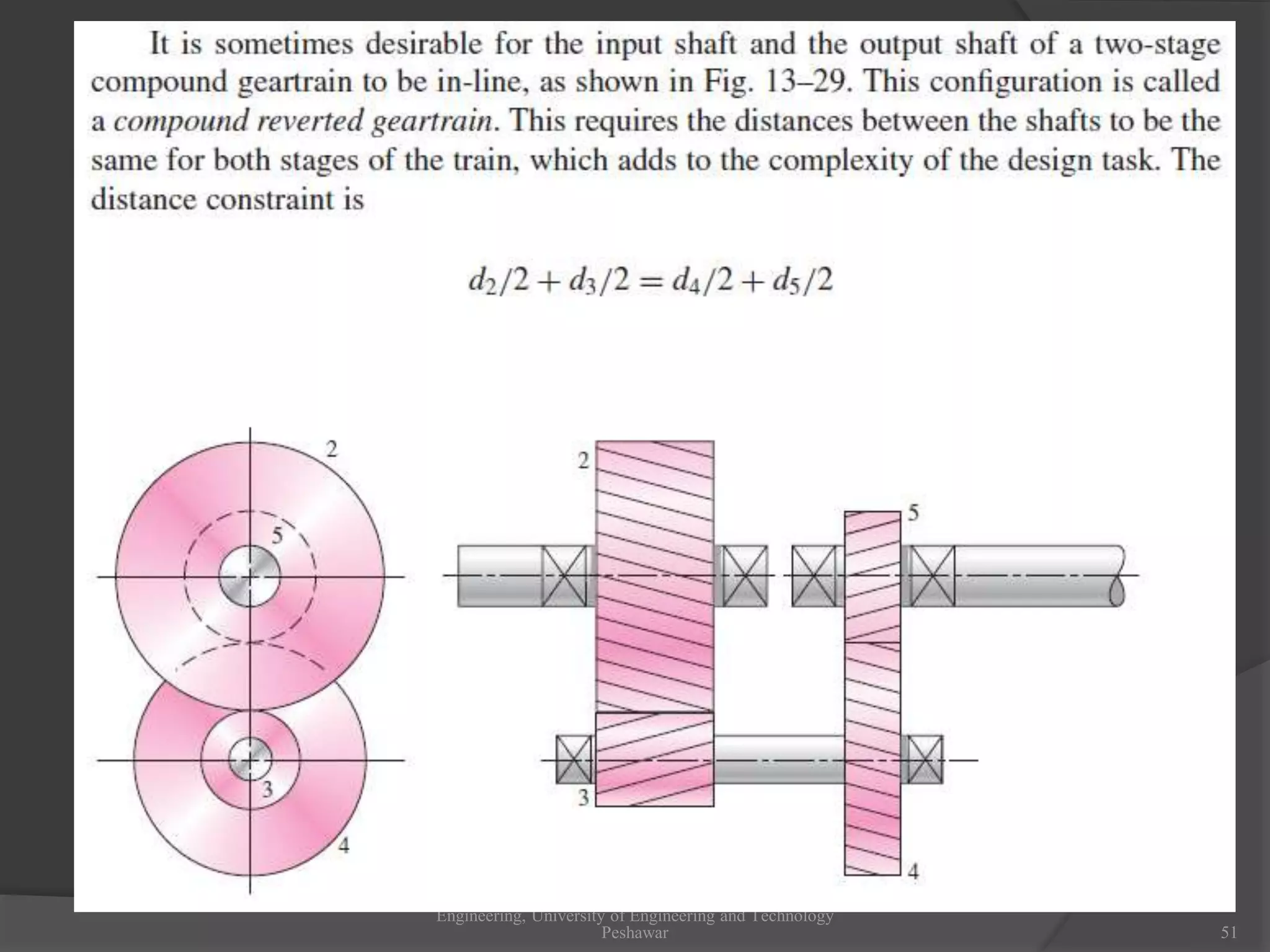
Machine Design II
Dr. Afzal Khan
University of Engineering and Technology
Peshawar Pakistan
afzal5426@gmail.com
Fall 2012
Dr Afzal Khan, Department of Mechanical Engineering, University of Engineering and Technology Peshawar
GEARS
 Power transmission is the movement of energy
from its place of generation to a location where it
is applied to performing useful work
 A gear is a component within a transmission
device that transmits rotational force to another
gear or device
TYPES OF GEARS
1. According to the position of axes of the shafts.
a. Parallel
1.Spur Gear
2.Helical Gear
3.Rack and Pinion
b. Intersecting
Bevel Gear
c. Non-intersecting and Non-parallel
worm and worm gears
SPUR GEAR
 Teeth is parallel to axis
of rotation
 Transmit power from
one to another parallel
shaft
 Used in Electric
screwdriver, oscillating
sprinkler, windup alarm
clock, washing machine
and clothes dryer.
External and Internal spur
Gear…
Helical Gear
 The teeth on helical gears are cut at an angle to
the face of the gear
 This gradual engagement makes helical gears
operate much more smoothly and quietly than
spur gears
Helical Gears
Herringbone gears
 To avoid axial thrust, two
helical gears of opposite
hand can be mounted side
by side, to cancel resulting
thrust forces
 Herringbone gears are
mostly used on heavy
machinery.
Rack and pinion
 Rack and pinion gears
are used to convert
rotation (From the pinion)
into linear motion (of the
rack)
 A perfect example of this
is the steering system on
many cars
Bevel gears
 Bevel gears are useful when the direction of a
shaft's rotation needs to be changed
 They are usually mounted on shafts that are 90
degrees apart, but can be designed to work at other
angles as well
 The teeth on bevel gears can be straight or spiral
 locomotives, marine applications, automobiles,
printing presses, cooling towers, power plants, steel
plants, railway track inspection machines, etc.
Straight and Spiral Bevel
Gears
WORM AND WORM GEAR
 Worm gears are used when large gear reductions
are needed. It is common for worm gears to have
reductions of 20:1, and even up to 300:1 or greater
 Many worm gears have an interesting property that
no other gear set has: the worm can easily turn the
gear, but the gear cannot turn the worm
 Worm gears are used widely in material handling
and transportation machinery, machine tools,
automobiles etc
WORM AND WORM GEAR
NOMENCLATURE OF
SPUR GEARS
NOMENCLATURE….
 Pitch surface: The surface of the imaginary rolling
cylinder (cone, etc.) that the toothed gear may be
considered to replace.
 Pitch circle: A right section of the pitch surface.
 Addendum circle: A circle bounding the ends of the
teeth, in a right section of the gear.
 Root (or dedendum) circle: The circle bounding the
spaces between the teeth, in a right section of the gear.
 Addendum: The radial distance between the pitch
circle and the addendum circle.
 Dedendum: The radial distance between the pitch
circle and the root circle.
 Clearance: The difference between the dedendum of
one gear and the addendum of the mating gear.
NOMENCLATURE….
 Face of a tooth: That part of the tooth surface lying outside
the pitch surface.
 Flank of a tooth: The part of the tooth surface lying inside
the pitch surface.
 Circular thickness (also called the tooth thickness): The
thickness of the tooth measured on the pitch circle. It is the
length of an arc and not the length of a straight line.
 Tooth space: pitch diameter The distance between adjacent
teeth measured on the pitch circle.
 Backlash: The difference between the circle thickness of one
gear and the tooth space of the mating gear.
 Circular pitch (Pc) : The width of a tooth and a space,
measured on the pitch circle.
N
D
Pc

NOMENCLATURE….
 Diametral pitch (Pd): The number of teeth of a gear
unit pitch diameter. The diametral pitch is, by
definition, the number of teeth divided by the pitch
diameter. That is,
Where
Pd = diametral pitch
N = number of teeth
D = pitch diameter
 Module (m): Pitch diameter divided by number of
teeth. The pitch diameter is usually specified in inches
or millimeters; in the former case the module is the
inverse of diametral pitch.
m = D/N
D
N
Pd 
Pitch Point
Line of Action,
Represents the direction
of action of forces
Pitch Circles
INVOLUTE ACTION
Dr Afzal Khan, Department of Mechanical Engineering, University of Engineering and Technology Peshawar
The pitch of bevel gears is measured at the large end of the tooth, and
both the circular pitch and the pitch diameter are calculated in the same
manner as for spur gears. It should be noted that the clearance is
uniform. The pitch angles are defined by the pitch cones meeting at the
apex, as shown in the figure. They are related to the tooth numbers by:
Dr Afzal Khan, Department of Mechanical Engineering, University of Engineering and Technology Peshawar
This figure shows that the shape
of the teeth, when projected on
the back cone, is the same as in
a spur gear having a radius equal
to the back-cone distance rb. This
is called Tredgold’s
approximation. The number of
teeth in this imaginary gear is
Dr Afzal Khan, Department of Mechanical Engineering, University of Engineering and Technology Peshawar
(b)(a) (c)
No matter whether the
gears are spur, helical,
bevel, or worm.
The absolute-value signs are used to permit complete freedom in
choosing positive and negative directions. In the case of spur and
parallel helical gears, the directions ordinarily correspond to the
right-hand rule and are positive for counterclockwise rotation.
Rotational directions are somewhat more difficult to deduce for
worm and crossed helical gearsets.
It is somewhat difficult to deduce directions for worm and crossed
helical gearsets.
Thrust, rotation, and hand relations for crossed helical gears. Note that
each pair of drawings refers to a single gearset. These relations also
apply to worm gearsets.
Dr Afzal Khan, Department of Mechanical
Engineering, University of Engineering and Technology
Peshawar 45
Dr Afzal Khan, Department of Mechanical
Engineering, University of Engineering and Technology
Peshawar 46
Gear 3 is an idler,
The number of
teeth cancels in
the equation and
it only effect the
direction of gear
6.
The train valve =
Dr Afzal Khan, Department of Mechanical
Engineering, University of Engineering and Technology
Peshawar 47
As a rough guideline, a train value of up to 10 to 1 can be obtained
with one pair of gears. Greater ratios can be obtained in less space
and with fewer dynamic problems by compounding additional pairs of
gears. A two-stage compound gear train, such as shown in the
following figure, can obtain a train value of up to 100 to 1.
Dr Afzal Khan, Department of Mechanical
Engineering, University of Engineering and Technology
Peshawar 48
Design of gear trains to accomplish a specific train
value:
1. Since numbers of teeth on gears must be integers, it is better to
determine them first
2. Obtain pitch diameters second.
3. Determine the number of stages necessary to obtain the
overall ratio.
4. Divide the overall ratio into portions to be accomplished in
each stage.
5. To minimize package size, keep the portions as evenly divided
between the stages as possible. (For example, in a two-stage
compound gear train, assign the square root of the overall train
value to each stage. If an exact train value is needed, attempt
to factor the overall train value into integer components for
each stage.)
6. Assign the smallest gear(s) to the minimum number of teeth
allowed for the specific ratio of each stage, in order to avoid
interference.
7. Applying the ratio for each stage, determine the necessary
number of teeth for the mating gears. Round to the nearest
integer and check that the resulting overall ratio is within
acceptable tolerance.
Dr Afzal Khan, Department of Mechanical
Engineering, University of Engineering and Technology
Peshawar 49
Dr Afzal Khan, Department of Mechanical
Engineering, University of Engineering and Technology
Peshawar 50
Dr Afzal Khan, Department of Mechanical
Engineering, University of Engineering and Technology
Peshawar 51
Dr Afzal Khan, Department of Mechanical
Engineering, University of Engineering and Technology
Peshawar 52
Dr Afzal Khan, Department of Mechanical
Engineering, University of Engineering and Technology
Peshawar 53
Dr Afzal Khan, Department of Mechanical
Engineering, University of Engineering and Technology
Peshawar 54
Dr Afzal Khan, Department of Mechanical
Engineering, University of Engineering and Technology
Peshawar 55
Dr Afzal Khan, Department of Mechanical
Engineering, University of Engineering and Technology
Peshawar 56
Dr Afzal Khan, Department of Mechanical
Engineering, University of Engineering and Technology
Peshawar 57
Dr Afzal Khan, Department of Mechanical
Engineering, University of Engineering and Technology
Peshawar 58
Dr Afzal Khan, Department of Mechanical
Engineering, University of Engineering and Technology
Peshawar 59
Dr Afzal Khan, Department of Mechanical
Engineering, University of Engineering and Technology
Peshawar 60
1. Beginning with the numeral 1 for the frame of the machine, we
shall designate the input gear as gear 2, and then number the
gears successively 3, 4, etc., until we arrive at the last gear in the
train.
1. Next, there may be several shafts involved, and usually one or
two gears are mounted on each shaft as well as other elements.
We shall designate the shafts, using lowercase letters of the
alphabet, a, b, c, etc.
WITH THIS NOTATION
1. The force exerted by gear 2 against gear 3 as F23.
2. The force of gear 2 against a shaft a is F2a
3. We can also write Fa2 to mean the force of a shaft a against gear
2.
Dr Afzal Khan, Department of Mechanical
Engineering, University of Engineering and Technology
Peshawar 61
The coordinate directions will usually be indicated by the x, y, and z
coordinates, and the radial and tangential directions by superscripts r
and t . With this notation, Ft
43 is the tangential component of the force
of gear 4 acting against gear 3.
Dr Afzal Khan, Department of Mechanical
Engineering, University of Engineering and Technology
Peshawar 62
Dr Afzal Khan, Department of Mechanical
Engineering, University of Engineering and Technology
Peshawar 63
Dr Afzal Khan, Department of Mechanical
Engineering, University of Engineering and Technology
Peshawar 64
Dr Afzal Khan, Department of Mechanical
Engineering, University of Engineering and Technology
Peshawar 65
Dr Afzal Khan, Department of Mechanical
Engineering, University of Engineering and Technology
Peshawar 66
Dr Afzal Khan, Department of Mechanical
Engineering, University of Engineering and Technology
Peshawar 67
Dr Afzal Khan, Department of Mechanical
Engineering, University of Engineering and Technology
Peshawar 68
Dr Afzal Khan, Department of Mechanical
Engineering, University of Engineering and Technology
Peshawar 69
Dr Afzal Khan, Department of Mechanical
Engineering, University of Engineering and Technology
Peshawar 70
Dr Afzal Khan, Department of Mechanical
Engineering, University of Engineering and Technology
Peshawar 71
Dr Afzal Khan, Department of Mechanical
Engineering, University of Engineering and Technology
Peshawar 72
Dr Afzal Khan, Department of Mechanical
Engineering, University of Engineering and Technology
Peshawar 73
Dr Afzal Khan, Department of Mechanical
Engineering, University of Engineering and Technology
Peshawar 74
Dr Afzal Khan, Department of Mechanical
Engineering, University of Engineering and Technology
Peshawar 75
Dr Afzal Khan, Department of Mechanical
Engineering, University of Engineering and Technology
Peshawar 76
Dr Afzal Khan, Department of Mechanical
Engineering, University of Engineering and Technology
Peshawar 77

Gearlecture

  • 1.
    Machine Design II Dr.Afzal Khan University of Engineering and Technology Peshawar Pakistan afzal5426@gmail.com Fall 2012 Dr Afzal Khan, Department of Mechanical Engineering, University of Engineering and Technology Peshawar
  • 3.
    GEARS  Power transmissionis the movement of energy from its place of generation to a location where it is applied to performing useful work  A gear is a component within a transmission device that transmits rotational force to another gear or device
  • 4.
    TYPES OF GEARS 1.According to the position of axes of the shafts. a. Parallel 1.Spur Gear 2.Helical Gear 3.Rack and Pinion b. Intersecting Bevel Gear c. Non-intersecting and Non-parallel worm and worm gears
  • 5.
    SPUR GEAR  Teethis parallel to axis of rotation  Transmit power from one to another parallel shaft  Used in Electric screwdriver, oscillating sprinkler, windup alarm clock, washing machine and clothes dryer.
  • 6.
  • 7.
    Helical Gear  Theteeth on helical gears are cut at an angle to the face of the gear  This gradual engagement makes helical gears operate much more smoothly and quietly than spur gears
  • 8.
  • 9.
    Herringbone gears  Toavoid axial thrust, two helical gears of opposite hand can be mounted side by side, to cancel resulting thrust forces  Herringbone gears are mostly used on heavy machinery.
  • 10.
    Rack and pinion Rack and pinion gears are used to convert rotation (From the pinion) into linear motion (of the rack)  A perfect example of this is the steering system on many cars
  • 11.
    Bevel gears  Bevelgears are useful when the direction of a shaft's rotation needs to be changed  They are usually mounted on shafts that are 90 degrees apart, but can be designed to work at other angles as well  The teeth on bevel gears can be straight or spiral  locomotives, marine applications, automobiles, printing presses, cooling towers, power plants, steel plants, railway track inspection machines, etc.
  • 12.
  • 13.
    WORM AND WORMGEAR  Worm gears are used when large gear reductions are needed. It is common for worm gears to have reductions of 20:1, and even up to 300:1 or greater  Many worm gears have an interesting property that no other gear set has: the worm can easily turn the gear, but the gear cannot turn the worm  Worm gears are used widely in material handling and transportation machinery, machine tools, automobiles etc
  • 14.
  • 15.
  • 16.
    NOMENCLATURE….  Pitch surface:The surface of the imaginary rolling cylinder (cone, etc.) that the toothed gear may be considered to replace.  Pitch circle: A right section of the pitch surface.  Addendum circle: A circle bounding the ends of the teeth, in a right section of the gear.  Root (or dedendum) circle: The circle bounding the spaces between the teeth, in a right section of the gear.  Addendum: The radial distance between the pitch circle and the addendum circle.  Dedendum: The radial distance between the pitch circle and the root circle.  Clearance: The difference between the dedendum of one gear and the addendum of the mating gear.
  • 17.
    NOMENCLATURE….  Face ofa tooth: That part of the tooth surface lying outside the pitch surface.  Flank of a tooth: The part of the tooth surface lying inside the pitch surface.  Circular thickness (also called the tooth thickness): The thickness of the tooth measured on the pitch circle. It is the length of an arc and not the length of a straight line.  Tooth space: pitch diameter The distance between adjacent teeth measured on the pitch circle.  Backlash: The difference between the circle thickness of one gear and the tooth space of the mating gear.  Circular pitch (Pc) : The width of a tooth and a space, measured on the pitch circle. N D Pc 
  • 18.
    NOMENCLATURE….  Diametral pitch(Pd): The number of teeth of a gear unit pitch diameter. The diametral pitch is, by definition, the number of teeth divided by the pitch diameter. That is, Where Pd = diametral pitch N = number of teeth D = pitch diameter  Module (m): Pitch diameter divided by number of teeth. The pitch diameter is usually specified in inches or millimeters; in the former case the module is the inverse of diametral pitch. m = D/N D N Pd 
  • 22.
    Pitch Point Line ofAction, Represents the direction of action of forces Pitch Circles
  • 24.
  • 29.
    Dr Afzal Khan,Department of Mechanical Engineering, University of Engineering and Technology Peshawar
  • 30.
    The pitch ofbevel gears is measured at the large end of the tooth, and both the circular pitch and the pitch diameter are calculated in the same manner as for spur gears. It should be noted that the clearance is uniform. The pitch angles are defined by the pitch cones meeting at the apex, as shown in the figure. They are related to the tooth numbers by: Dr Afzal Khan, Department of Mechanical Engineering, University of Engineering and Technology Peshawar
  • 31.
    The pitch ofbevel gears is measured at the large end of the tooth, and both the circular pitch and the pitch diameter are calculated in the same manner as for spur gears. It should be noted that the clearance is uniform. The pitch angles are defined by the pitch cones meeting at the apex, as shown in the figure. They are related to the tooth numbers by: Dr Afzal Khan, Department of Mechanical Engineering, University of Engineering and Technology Peshawar This figure shows that the shape of the teeth, when projected on the back cone, is the same as in a spur gear having a radius equal to the back-cone distance rb. This is called Tredgold’s approximation. The number of teeth in this imaginary gear is
  • 32.
    Dr Afzal Khan,Department of Mechanical Engineering, University of Engineering and Technology Peshawar
  • 33.
  • 44.
    No matter whetherthe gears are spur, helical, bevel, or worm. The absolute-value signs are used to permit complete freedom in choosing positive and negative directions. In the case of spur and parallel helical gears, the directions ordinarily correspond to the right-hand rule and are positive for counterclockwise rotation. Rotational directions are somewhat more difficult to deduce for worm and crossed helical gearsets. It is somewhat difficult to deduce directions for worm and crossed helical gearsets.
  • 45.
    Thrust, rotation, andhand relations for crossed helical gears. Note that each pair of drawings refers to a single gearset. These relations also apply to worm gearsets. Dr Afzal Khan, Department of Mechanical Engineering, University of Engineering and Technology Peshawar 45
  • 46.
    Dr Afzal Khan,Department of Mechanical Engineering, University of Engineering and Technology Peshawar 46 Gear 3 is an idler, The number of teeth cancels in the equation and it only effect the direction of gear 6. The train valve =
  • 47.
    Dr Afzal Khan,Department of Mechanical Engineering, University of Engineering and Technology Peshawar 47 As a rough guideline, a train value of up to 10 to 1 can be obtained with one pair of gears. Greater ratios can be obtained in less space and with fewer dynamic problems by compounding additional pairs of gears. A two-stage compound gear train, such as shown in the following figure, can obtain a train value of up to 100 to 1.
  • 48.
    Dr Afzal Khan,Department of Mechanical Engineering, University of Engineering and Technology Peshawar 48 Design of gear trains to accomplish a specific train value: 1. Since numbers of teeth on gears must be integers, it is better to determine them first 2. Obtain pitch diameters second. 3. Determine the number of stages necessary to obtain the overall ratio. 4. Divide the overall ratio into portions to be accomplished in each stage. 5. To minimize package size, keep the portions as evenly divided between the stages as possible. (For example, in a two-stage compound gear train, assign the square root of the overall train value to each stage. If an exact train value is needed, attempt to factor the overall train value into integer components for each stage.) 6. Assign the smallest gear(s) to the minimum number of teeth allowed for the specific ratio of each stage, in order to avoid interference. 7. Applying the ratio for each stage, determine the necessary number of teeth for the mating gears. Round to the nearest integer and check that the resulting overall ratio is within acceptable tolerance.
  • 49.
    Dr Afzal Khan,Department of Mechanical Engineering, University of Engineering and Technology Peshawar 49
  • 50.
    Dr Afzal Khan,Department of Mechanical Engineering, University of Engineering and Technology Peshawar 50
  • 51.
    Dr Afzal Khan,Department of Mechanical Engineering, University of Engineering and Technology Peshawar 51
  • 52.
    Dr Afzal Khan,Department of Mechanical Engineering, University of Engineering and Technology Peshawar 52
  • 53.
    Dr Afzal Khan,Department of Mechanical Engineering, University of Engineering and Technology Peshawar 53
  • 54.
    Dr Afzal Khan,Department of Mechanical Engineering, University of Engineering and Technology Peshawar 54
  • 55.
    Dr Afzal Khan,Department of Mechanical Engineering, University of Engineering and Technology Peshawar 55
  • 56.
    Dr Afzal Khan,Department of Mechanical Engineering, University of Engineering and Technology Peshawar 56
  • 57.
    Dr Afzal Khan,Department of Mechanical Engineering, University of Engineering and Technology Peshawar 57
  • 58.
    Dr Afzal Khan,Department of Mechanical Engineering, University of Engineering and Technology Peshawar 58
  • 59.
    Dr Afzal Khan,Department of Mechanical Engineering, University of Engineering and Technology Peshawar 59
  • 60.
    Dr Afzal Khan,Department of Mechanical Engineering, University of Engineering and Technology Peshawar 60 1. Beginning with the numeral 1 for the frame of the machine, we shall designate the input gear as gear 2, and then number the gears successively 3, 4, etc., until we arrive at the last gear in the train. 1. Next, there may be several shafts involved, and usually one or two gears are mounted on each shaft as well as other elements. We shall designate the shafts, using lowercase letters of the alphabet, a, b, c, etc. WITH THIS NOTATION 1. The force exerted by gear 2 against gear 3 as F23. 2. The force of gear 2 against a shaft a is F2a 3. We can also write Fa2 to mean the force of a shaft a against gear 2.
  • 61.
    Dr Afzal Khan,Department of Mechanical Engineering, University of Engineering and Technology Peshawar 61 The coordinate directions will usually be indicated by the x, y, and z coordinates, and the radial and tangential directions by superscripts r and t . With this notation, Ft 43 is the tangential component of the force of gear 4 acting against gear 3.
  • 62.
    Dr Afzal Khan,Department of Mechanical Engineering, University of Engineering and Technology Peshawar 62
  • 63.
    Dr Afzal Khan,Department of Mechanical Engineering, University of Engineering and Technology Peshawar 63
  • 64.
    Dr Afzal Khan,Department of Mechanical Engineering, University of Engineering and Technology Peshawar 64
  • 65.
    Dr Afzal Khan,Department of Mechanical Engineering, University of Engineering and Technology Peshawar 65
  • 66.
    Dr Afzal Khan,Department of Mechanical Engineering, University of Engineering and Technology Peshawar 66
  • 67.
    Dr Afzal Khan,Department of Mechanical Engineering, University of Engineering and Technology Peshawar 67
  • 68.
    Dr Afzal Khan,Department of Mechanical Engineering, University of Engineering and Technology Peshawar 68
  • 69.
    Dr Afzal Khan,Department of Mechanical Engineering, University of Engineering and Technology Peshawar 69
  • 70.
    Dr Afzal Khan,Department of Mechanical Engineering, University of Engineering and Technology Peshawar 70
  • 71.
    Dr Afzal Khan,Department of Mechanical Engineering, University of Engineering and Technology Peshawar 71
  • 72.
    Dr Afzal Khan,Department of Mechanical Engineering, University of Engineering and Technology Peshawar 72
  • 73.
    Dr Afzal Khan,Department of Mechanical Engineering, University of Engineering and Technology Peshawar 73
  • 74.
    Dr Afzal Khan,Department of Mechanical Engineering, University of Engineering and Technology Peshawar 74
  • 75.
    Dr Afzal Khan,Department of Mechanical Engineering, University of Engineering and Technology Peshawar 75
  • 76.
    Dr Afzal Khan,Department of Mechanical Engineering, University of Engineering and Technology Peshawar 76
  • 77.
    Dr Afzal Khan,Department of Mechanical Engineering, University of Engineering and Technology Peshawar 77