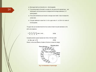
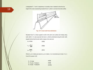
This document provides information on bevel gears, including their design, applications, advantages, and disadvantages. It discusses straight and spiral bevel gear types and proportions. Formulas are presented for calculating forces, bending stresses, contact stresses, and permissible stress values for bevel gear design. Diagrams illustrate bevel gear geometry, terminology, and force analysis. The document is intended to inform the design of bevel gear elements and machine components.


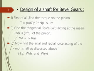
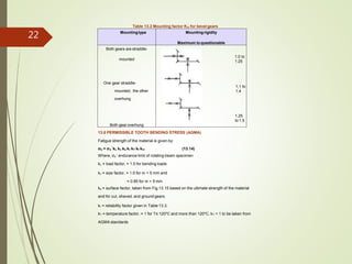
![Permissible bending stress is given by
(13.15)b
[σ ]=
σe
s
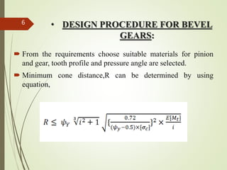
Hence the design equation from bending consideration is,
σb ≤ [σb ] (13.16)
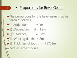
Bevel gear surface fatigue stress can be calculated as for spur gears, with only two
modifications.
H p V o m
Ft
σ =C K K K
bdI
(13.17)
13.7 CONTACT STRESS:
1.23 times the Cp values given in the Table13.4 are taken to account for a somewhat
more localized contact area than spur gears.
Table 13.4 Elastic Coefficient Cp for spur gears, in (MPa)0.5
s
Pinion Material
(µ = 0.3 in all cases)
Gear material
Steel
Ca
t iron Al Bronze Tin Bron ze
Steel,E=307GPa 191 166 162 1
5
8
Cast iron, E = 131GPa 166 149 149 1
4
5
Al Bronze, E = 121GPa 162 149 145 1
4
2
Tin Bronze, E = 110GPa 158 145 141 1
3
7
24](https://image.slidesharecdn.com/dmeppt1-180426072313/85/Dme-ppt-24-320.jpg)
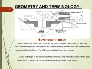
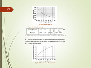
![Surface fatigue strength of the material is given by,
σsf = σsf’ KL KH KR KT (13.18)
Where σsf’ = surface fatigue strength of the material given in Table 13.7
KL = Life factor given in Fig.13.19
Table 13.7 Surface fatigue strength σsf (MPa) for metallic spur gear,
(107
cycle life 99% reliability and temperature < 120o
C)
Material σsf (MPa)
Steel 2.8 (Bhn) – 69 MPa
Nodulariron 0.95 [ 2.8 (Bhn) – 69 MPa]
Cast iron, grade 20 379
Cast iron, grade 30 482
Cast iron, grade 40 551
Tin Bronze, AGMA 2C ( 11% Sn) 207
Aluminium Bronze (ASTM b 148 – 52) (Alloy 9C – H.T ) 448
Fig.13.19 Life factorKL
26](https://image.slidesharecdn.com/dmeppt1-180426072313/85/Dme-ppt-26-320.jpg)
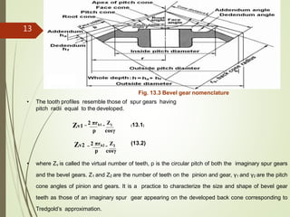
![KH is hardness ratio factor, K the Brinell hardness of the pinion by Brinell hardness of
the gear as given in Fig. 13.20.
KH = 1.0 for K < 1.2
KR = Reliability factor, given in Table 13.3.
Fig.13.20 Hardness ratio factor, KH
KT = temperature factor,
= 1 for T≤ 120o
C based on lubricant temperature.
Above 120o
C, it is less than 1 to be taken from AGMA standards.
Allowable surface fatigue stress for design is given by
[σH ] = σSf / s (13.19)
Factor of safety s = 1.1 to 1.5
Hence Design equation is:
σH ≤ [ σH ] (13.20)
------------------
27](https://image.slidesharecdn.com/dmeppt1-180426072313/85/Dme-ppt-27-320.jpg)