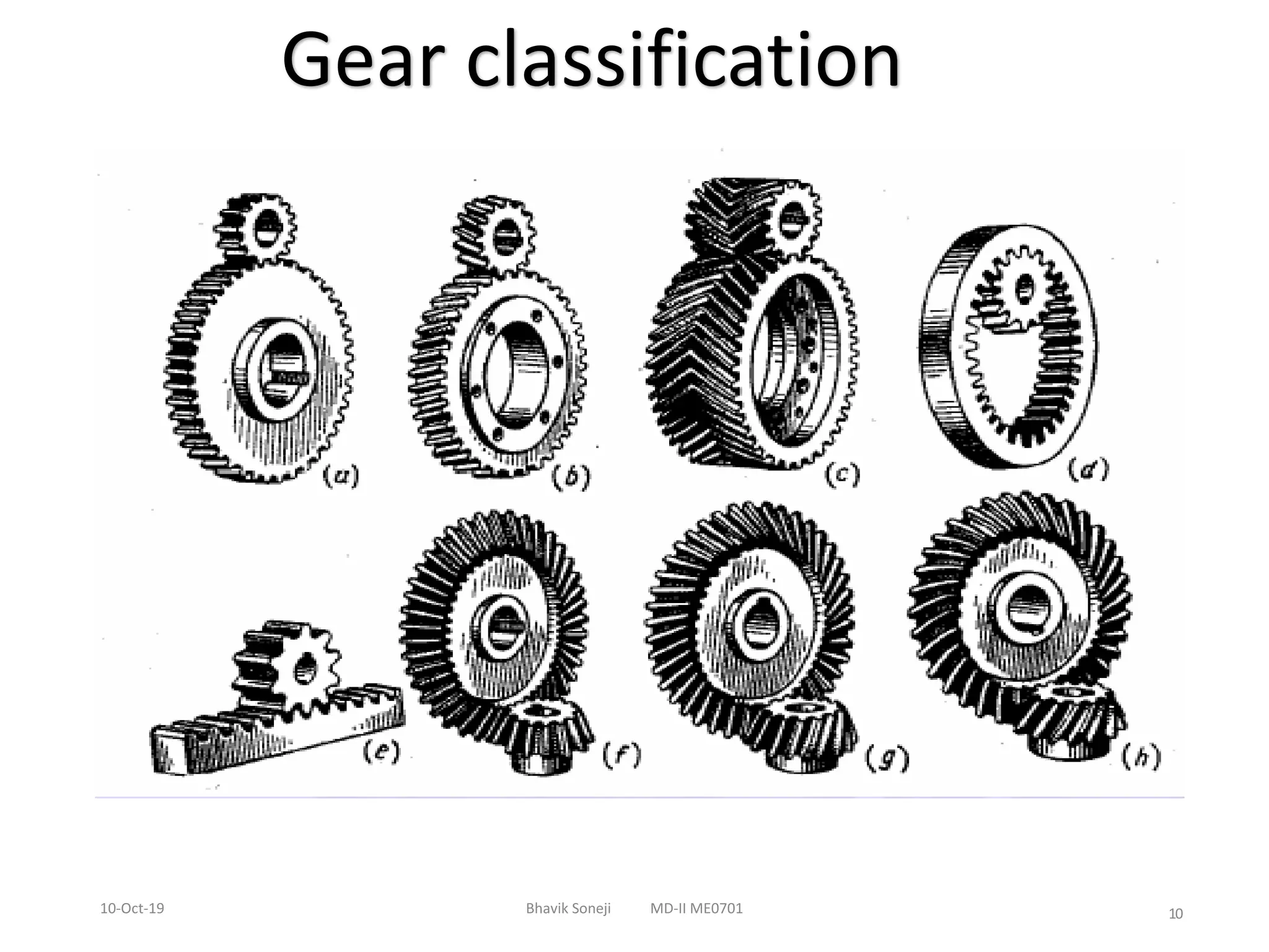
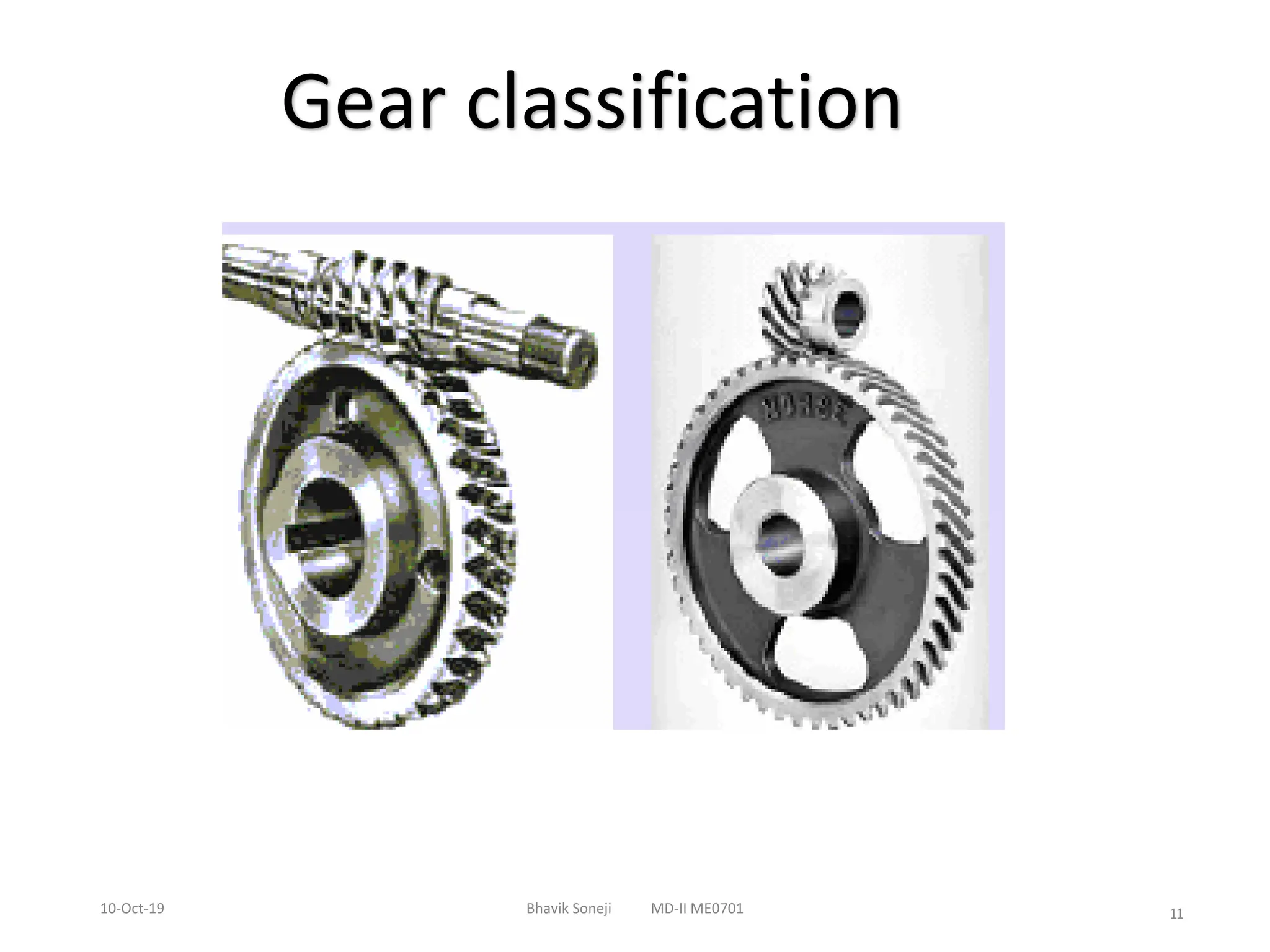
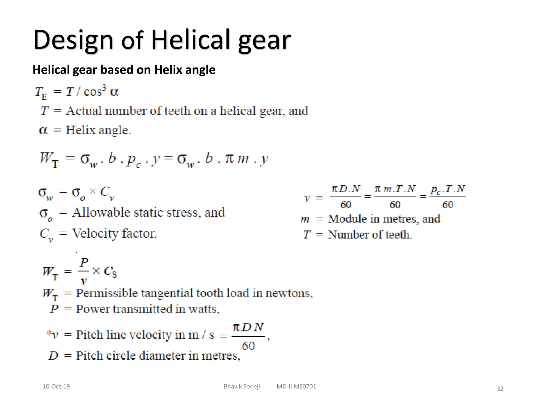
Machine Design –II
Gears-
Spur Gears & Bevel Gears
By
Bhavik Soneji
Department of Mechanical Engineering
Indus University
Gears Overview
• Classification
• Applications
• Terminologies
• Materials
• Undercut & interference
• Law of gearing
• Tooth failure
• Design of spur gear – dynamic , static , wearing
loading condition
• Design of helical gear - dynamic , static , wearing
loading condition
10-Oct-19 Bhavik Soneji MD-II ME0701 2
3
10-Oct-19 Bhavik Soneji MD-II ME0701
Identify the type of gear ???
4
10-Oct-19 Bhavik Soneji MD-II ME0701
Identify the type of gear ???
5
10-Oct-19 Bhavik Soneji MD-II ME0701
Identify the type of gear ???
6
10-Oct-19 Bhavik Soneji MD-II ME0701
Identify the type of gear ???
7
10-Oct-19 Bhavik Soneji MD-II ME0701
Identify the type of gear ???
8
10-Oct-19 Bhavik Soneji MD-II ME0701
Identify the type of gear ???
9
10-Oct-19 Bhavik Soneji MD-II ME0701
Identify the type of gear ???
10
10-Oct-19 Bhavik Soneji MD-II ME0701
Gear classification
11
10-Oct-19 Bhavik Soneji MD-II ME0701
Gear classification
12
10-Oct-19 Bhavik Soneji MD-II ME0701
Gear classification
SPUR GEAR
• Teeth is parallel to axis of
rotation
• Transmit power from one
shaft to another parallel
shaft
• Used in Electric screwdriver,
oscillating sprinkler, windup
alarm clock, washing machine
and clothes dryer
Helical Gear
• The teeth on helical gears are cut at an angle to the face of the
gear
• This gradual engagement makes helical gears operate much
more smoothly and quietly than spur gears
• One interesting thing about helical gears is that if the angles
of the gear teeth are correct, they can be mounted on
perpendicular shafts, adjusting the rotation angle by 90
degrees
Herringbone gears
• To avoid axial thrust, two
helical gears of opposite
hand can be mounted side
by side, to cancel resulting
thrust forces
• Herringbone gears are
mostly used on heavy
machinery.
Rack and pinion
• Rack and pinion gears are used to convert rotation (From the
pinion) into linear motion (of the rack)
• A perfect example of this is the steering system on manycars
Bevel gears
• Bevel gears are useful when the direction of a shaft's rotation needs to be changed
• They are usually mounted on shafts that are 90 degrees apart, but can be designed
to work at other angles as well
• The teeth on bevel gears can be straight, spiral or hypoid
• locomotives, marine applications, automobiles, printing presses, cooling
towers, power plants, steel plants, railway trackinspection machines, etc.
WORM AND WORMGEAR
• Worm gears are used when large gear reductions are needed. It is common for
worm gears to have reductions of 20:1, and even up to 300:1 orgreater
• Many worm gears have an interesting property that no other gear set has: theworm
can easily turn the gear, but the gear cannot turn theworm
• Worm gears are used widely in material handling and transportationmachinery,
machine tools, automobiles etc
19
10-Oct-19 Bhavik Soneji MD-II ME0701
Gear Terminology for Involute
20
10-Oct-19 Bhavik Soneji MD-II ME0701
Gear Terminology for Involute
Pitch circle diameter
Circular pitch
Diametral pitch
Module
Clearance
Backlash
Tooth thickness
Tooth space
Pressure angle
Crowning
21
10-Oct-19 Bhavik Soneji MD-II ME0701
Gear Terminology for Involute
22
10-Oct-19 Bhavik Soneji MD-II ME0701
Clearance
23
10-Oct-19 Bhavik Soneji MD-II ME0701
Backlash
24
10-Oct-19 Bhavik Soneji MD-II ME0701
Gear material & manufacturing Process
Manufacturing Process Involved for gears are ,
Casting
Metal Removal Process
Milling
Hobbing
Broaching
Forming
Followed by Heat Treatment & minor machining
25
10-Oct-19 Bhavik Soneji MD-II ME0701
Gear material & manufacturing Process
Taking external/environmental considerations, force/load conditions and
noise considerations as well materials like
brass, bronze, phosphor bronze etc for medium to heavy working
conditions.
steel & cast iron for heavy duty applications
Materials like plastics are used in toys/light duty applications.
While using gears of steel or cast iron material, appropriate heat
treatment such as case hardening is done to give sufficient surface
hardness for wear resistance and sufficient toughness at core to withstand
loads applied.
26
10-Oct-19 Bhavik Soneji MD-II ME0701
Law of gearing
The fundamental law of gearing states that the angular velocity ratio between
the gears of a gear set must remain constant throughout the mesh.
The law of gearing states that the common normal at the point of contact between a
pair of teeth must always pass through the pitch point.
Pitch point is the common point of contact between two pitch circles of the gears in
mesh.
27
10-Oct-19 Bhavik Soneji MD-II ME0701
Design of spur gear
Spur gear Strength based on Lewi’s Equation
y = Lewi’s form factor
28
10-Oct-19 Bhavik Soneji MD-II ME0701
Design of spur gear
Standard Values for Modules : 1, 1.25, 1.5, 2, 2.5, 3, 4, 5, 6, 8, 10, 12, 16,20, 25,
32, 40 and 50.
29
10-Oct-19 Bhavik Soneji MD-II ME0701
Design of spur gear
30
10-Oct-19 Bhavik Soneji MD-II ME0701
Numerical -Design of spur gear
•A gear drive is required to transmit a maximum power of 22.5
kW. The velocity ratio is 1:2 and r.p.m. of the pinion is 200. The
approximate centre distance between the shafts may be taken
as 600 mm. The teeth have 20° stub involute profiles. The static
stress for the gear material (which is cast iron) may be taken as
60 MPa and face width as 10 times the module. Find the
module, face width and number of teeth on each gear.
31
10-Oct-19 Bhavik Soneji MD-II ME0701
Numerical -Design of spur gear
A pair of straight teeth spur gears is to transmit 20 kW when
the pinion rotates at 300 r.p.m. The velocity ratio is 1 : 3. The
allowable static stresses for the pinion and gear materials are
120 MPa and 100 MPa respectively. The pinion has 15 teeth
and its face width is 14 times the module. The teeth have 20°
full depth involute profile for velocity less than 12
m/s.Determine: 1. module; 2. face width; and 3. pitch circle
diameters of the pinion and the gear from the standpoint of
strength only, taking into consideration the effect of the
dynamic loading.
32
10-Oct-19 Bhavik Soneji MD-II ME0701
Design of Helical gear
Helical gear based on Helix angle
33
10-Oct-19 Bhavik Soneji MD-II ME0701
Numerical -Design of Helical gear
A pair of helical gears is to transmit 15 kW. The teeth are 20°
stub in diametral plane and have a helix angle of 45°. The
pinion runs at 10 000 r.p.m. and has 80 mm pitch diameter. The
gear has 320 mm pitch diameter. If the gears are made of cast
steel having allowable static strength of 100 MPa; determine a
suitable module and face width from static strength
considerations and check the gears for wear, given σes = 618
MPa.

Spur gear and helical gear machine design

  • 1.
    Machine Design –II Gears- SpurGears & Bevel Gears By Bhavik Soneji Department of Mechanical Engineering Indus University
  • 2.
    Gears Overview • Classification •Applications • Terminologies • Materials • Undercut & interference • Law of gearing • Tooth failure • Design of spur gear – dynamic , static , wearing loading condition • Design of helical gear - dynamic , static , wearing loading condition 10-Oct-19 Bhavik Soneji MD-II ME0701 2
  • 3.
    3 10-Oct-19 Bhavik SonejiMD-II ME0701 Identify the type of gear ???
  • 4.
    4 10-Oct-19 Bhavik SonejiMD-II ME0701 Identify the type of gear ???
  • 5.
    5 10-Oct-19 Bhavik SonejiMD-II ME0701 Identify the type of gear ???
  • 6.
    6 10-Oct-19 Bhavik SonejiMD-II ME0701 Identify the type of gear ???
  • 7.
    7 10-Oct-19 Bhavik SonejiMD-II ME0701 Identify the type of gear ???
  • 8.
    8 10-Oct-19 Bhavik SonejiMD-II ME0701 Identify the type of gear ???
  • 9.
    9 10-Oct-19 Bhavik SonejiMD-II ME0701 Identify the type of gear ???
  • 10.
    10 10-Oct-19 Bhavik SonejiMD-II ME0701 Gear classification
  • 11.
    11 10-Oct-19 Bhavik SonejiMD-II ME0701 Gear classification
  • 12.
    12 10-Oct-19 Bhavik SonejiMD-II ME0701 Gear classification
  • 13.
    SPUR GEAR • Teethis parallel to axis of rotation • Transmit power from one shaft to another parallel shaft • Used in Electric screwdriver, oscillating sprinkler, windup alarm clock, washing machine and clothes dryer
  • 14.
    Helical Gear • Theteeth on helical gears are cut at an angle to the face of the gear • This gradual engagement makes helical gears operate much more smoothly and quietly than spur gears • One interesting thing about helical gears is that if the angles of the gear teeth are correct, they can be mounted on perpendicular shafts, adjusting the rotation angle by 90 degrees
  • 15.
    Herringbone gears • Toavoid axial thrust, two helical gears of opposite hand can be mounted side by side, to cancel resulting thrust forces • Herringbone gears are mostly used on heavy machinery.
  • 16.
    Rack and pinion •Rack and pinion gears are used to convert rotation (From the pinion) into linear motion (of the rack) • A perfect example of this is the steering system on manycars
  • 17.
    Bevel gears • Bevelgears are useful when the direction of a shaft's rotation needs to be changed • They are usually mounted on shafts that are 90 degrees apart, but can be designed to work at other angles as well • The teeth on bevel gears can be straight, spiral or hypoid • locomotives, marine applications, automobiles, printing presses, cooling towers, power plants, steel plants, railway trackinspection machines, etc.
  • 18.
    WORM AND WORMGEAR •Worm gears are used when large gear reductions are needed. It is common for worm gears to have reductions of 20:1, and even up to 300:1 orgreater • Many worm gears have an interesting property that no other gear set has: theworm can easily turn the gear, but the gear cannot turn theworm • Worm gears are used widely in material handling and transportationmachinery, machine tools, automobiles etc
  • 19.
    19 10-Oct-19 Bhavik SonejiMD-II ME0701 Gear Terminology for Involute
  • 20.
    20 10-Oct-19 Bhavik SonejiMD-II ME0701 Gear Terminology for Involute Pitch circle diameter Circular pitch Diametral pitch Module Clearance Backlash Tooth thickness Tooth space Pressure angle Crowning
  • 21.
    21 10-Oct-19 Bhavik SonejiMD-II ME0701 Gear Terminology for Involute
  • 22.
    22 10-Oct-19 Bhavik SonejiMD-II ME0701 Clearance
  • 23.
    23 10-Oct-19 Bhavik SonejiMD-II ME0701 Backlash
  • 24.
    24 10-Oct-19 Bhavik SonejiMD-II ME0701 Gear material & manufacturing Process Manufacturing Process Involved for gears are , Casting Metal Removal Process Milling Hobbing Broaching Forming Followed by Heat Treatment & minor machining
  • 25.
    25 10-Oct-19 Bhavik SonejiMD-II ME0701 Gear material & manufacturing Process Taking external/environmental considerations, force/load conditions and noise considerations as well materials like brass, bronze, phosphor bronze etc for medium to heavy working conditions. steel & cast iron for heavy duty applications Materials like plastics are used in toys/light duty applications. While using gears of steel or cast iron material, appropriate heat treatment such as case hardening is done to give sufficient surface hardness for wear resistance and sufficient toughness at core to withstand loads applied.
  • 26.
    26 10-Oct-19 Bhavik SonejiMD-II ME0701 Law of gearing The fundamental law of gearing states that the angular velocity ratio between the gears of a gear set must remain constant throughout the mesh. The law of gearing states that the common normal at the point of contact between a pair of teeth must always pass through the pitch point. Pitch point is the common point of contact between two pitch circles of the gears in mesh.
  • 27.
    27 10-Oct-19 Bhavik SonejiMD-II ME0701 Design of spur gear Spur gear Strength based on Lewi’s Equation y = Lewi’s form factor
  • 28.
    28 10-Oct-19 Bhavik SonejiMD-II ME0701 Design of spur gear Standard Values for Modules : 1, 1.25, 1.5, 2, 2.5, 3, 4, 5, 6, 8, 10, 12, 16,20, 25, 32, 40 and 50.
  • 29.
    29 10-Oct-19 Bhavik SonejiMD-II ME0701 Design of spur gear
  • 30.
    30 10-Oct-19 Bhavik SonejiMD-II ME0701 Numerical -Design of spur gear •A gear drive is required to transmit a maximum power of 22.5 kW. The velocity ratio is 1:2 and r.p.m. of the pinion is 200. The approximate centre distance between the shafts may be taken as 600 mm. The teeth have 20° stub involute profiles. The static stress for the gear material (which is cast iron) may be taken as 60 MPa and face width as 10 times the module. Find the module, face width and number of teeth on each gear.
  • 31.
    31 10-Oct-19 Bhavik SonejiMD-II ME0701 Numerical -Design of spur gear A pair of straight teeth spur gears is to transmit 20 kW when the pinion rotates at 300 r.p.m. The velocity ratio is 1 : 3. The allowable static stresses for the pinion and gear materials are 120 MPa and 100 MPa respectively. The pinion has 15 teeth and its face width is 14 times the module. The teeth have 20° full depth involute profile for velocity less than 12 m/s.Determine: 1. module; 2. face width; and 3. pitch circle diameters of the pinion and the gear from the standpoint of strength only, taking into consideration the effect of the dynamic loading.
  • 32.
    32 10-Oct-19 Bhavik SonejiMD-II ME0701 Design of Helical gear Helical gear based on Helix angle
  • 33.
    33 10-Oct-19 Bhavik SonejiMD-II ME0701 Numerical -Design of Helical gear A pair of helical gears is to transmit 15 kW. The teeth are 20° stub in diametral plane and have a helix angle of 45°. The pinion runs at 10 000 r.p.m. and has 80 mm pitch diameter. The gear has 320 mm pitch diameter. If the gears are made of cast steel having allowable static strength of 100 MPa; determine a suitable module and face width from static strength considerations and check the gears for wear, given σes = 618 MPa.