This document provides an overview of embedded system design. It defines embedded systems and compares them to general computing systems. Embedded systems are application specific combinations of hardware and software designed to perform dedicated functions. The document classifies embedded systems based on generation, complexity, determinism, and triggering. It describes common embedded system components like processors, memory, sensors, actuators and communication interfaces. It outlines the purpose of embedded systems in data collection, communication, processing, monitoring, control and interfaces. Finally, it discusses memory types and processor technologies used in embedded systems.
Overview of embedded systems, their definitions, components, applications, classifications, and technologies used in design.
Key components include software, RTOS, processors, memory types, sensors, and actuators. Classification based on generation, complexity, real-time behavior (hard/soft), and triggering mechanisms.
Various applications including data collection, processing, control systems, and user interfaces for embedded devices.
Differences between embedded systems and general computing systems regarding purpose, performance, and architecture.
Discussion on core components like microprocessors, microcontrollers, DSPs, and their respective applications.
Overview of different types of memory used in embedded systems, including ROM, RAM, and their applications.I/O subsystems including sensors, actuators, communication interfaces, and various connection types.Details on onboard and external communication interfaces such as I2C, SPI, USB, Bluetooth, and their specifications.
Understanding embedded firmware, its development, and essential additional components for system functionality.
Challenges in optimizing design metrics like cost, size, performance, and time-to-market in embedded systems.
Key embedded system technologies focusing on processor technology, IC technology, and design technology.
Overview of the methodologies for system design, including compilation, libraries, and verification process.
Unit - 1: Introduction
Embedded System-Definition
(Embedded system vs. general computing
systems)
Classification
application areas and purpose of embedded
systems
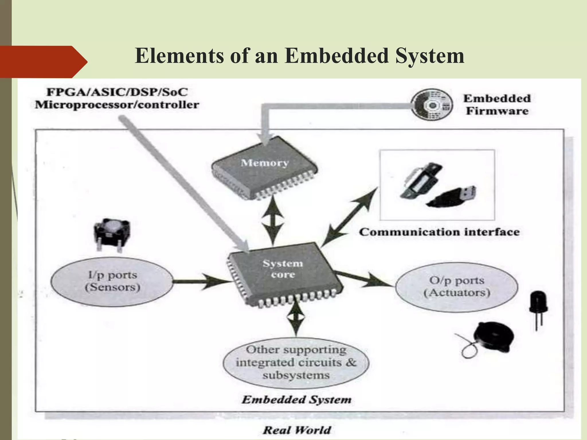
The typical embedded system
Core of the embedded system
Memory, Sensors and Actuators
Communication Interface
3.
Unit - 1: Introduction (cont..)
Design challenge-optimizing design metrics
processor technology
IC technology
Design Technology.
4.
Embedded System-Definition
Anembedded system is an electronic / electro-
mechanical system designed to perform a
specific function and a combination of both
hardware and firmware (software).
Every embedded system is unique and the
hardware as well as the firmware is highly
specialized to the application domain.
5.
Embedded System- Applications
Embedded systems are becoming an inevitable
part of any product or equipment in all fields
including
household appliances
telecommunications
medical equipment
industrial control
consumer products, etc.
Classification of Embedded
Systems
Some criteria used in the classification :
1. Based on generation
2. Complexity and performance requirements
3. Based on deterministic behaviour
4. Based on triggering
8.
Classification based on
generation
1. First generation
Using 8-bit processors (8085, Z80), or 4 – bit
microcontrollers
Simple hardware circuits with firmware
developed in Assembly code
Examples:
Digital telephone keypads
Stepper motor control units
9.
Classification based on
generation
2. Second generation
Using 16 bit microprocessor and 8 or 16 bit
micro controllers
Instruction set is much more complex and
powerful
Some of the embedded systems uses
Embedded OS for their operation
Examples:
Data acquisition systems etc.
10.
Classification based on
generation
3. Third generation
Using 32-bit processors (Pentium, Motorola
68K), or 16 – bit microcontrollers, DSP
processors, ASICs
Application and domain specific processors
Instruction pipelining
Dedicated Embedded real time and General
purpose OS
Examples:
Robotics, media
Industrial process control, networking, etc
11.
Classification based on
generation
4. Fourth generation
Using System on chips (SoCs), reconfigurable
processors, multi-core processors
High performance, Tight integration and
miniaturization, real time OS
SoC: Implements a total system on a chip by
integrating different functionalities with a
processor core on an IC
Examples:
Smart phone devices, Mobile internet devices,
etc.
Embedded Systems
Components
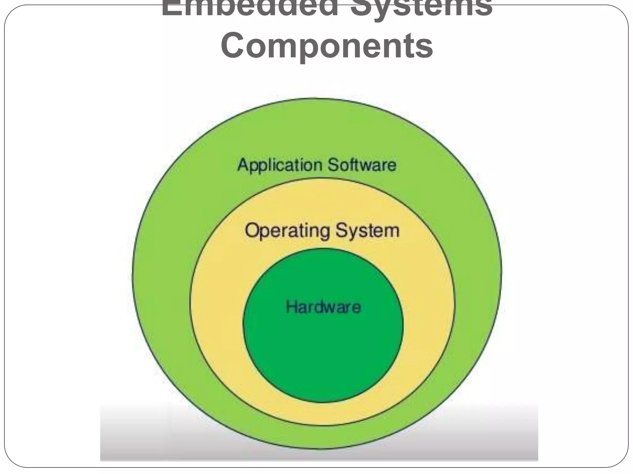
ApplicationSoftware.
Real-Time Operating System (RTOS) supervises
the utility software and offer a mechanism to let
the processor run a process as in step with
scheduling by means of following a plan to
manipulate the latencies.
RTOS defines the manner the system works. It units
the rules throughout the execution of application
software. A small scale embedded device won’t
have RTOS.
Hardware.
14.
Based on complexityand
performance
1. Small scale embedded systems
Simple in application needs
Built around low performance and low cost 8
or 16 bit Microprocessors / Microcontrollers
An electronic toy
May or may not contain an OS
15.
Based on complexityand
performance
2. Medium scale embedded systems
Slightly complex in hardware and firmware
(software) requirements
Built around medium performance, Low cost
16 or 32 bit MPs / MCs or DSPs
Software:
Usually contains Embedded OS
Either General purpose or real time OS
16.
Based on complexityand
performance
3. Large scale Embedded systems/ complex
systems
Highly complex hardware and firmware
requirements
High performance 32 or 64 bit Processors /
controllers or reconfigurable systems on-chip
(RSoC) or multi-core processors and
programmable devices
May contain Co-units / hardware accelerators for
offloading the processing requirements from the
main processor of the system
17.
Based on complexityand
performance
3. Large scale Embedded systems/ complex
systems
Employed in mission critical applications
demanding high performance
Examples:
Decoding / encoding of media
Cryptographic function implementation, etc
18.
Based on deterministicsystems
It is applicable for real time systems
The application / task execution behaviour of
an embedded system can be
Either deterministic
Or non-deterministic
Based on execution behaviour, real time
embedded systems are classified as
Hard
Soft
19.
Frank Drews
Real-Time Systems
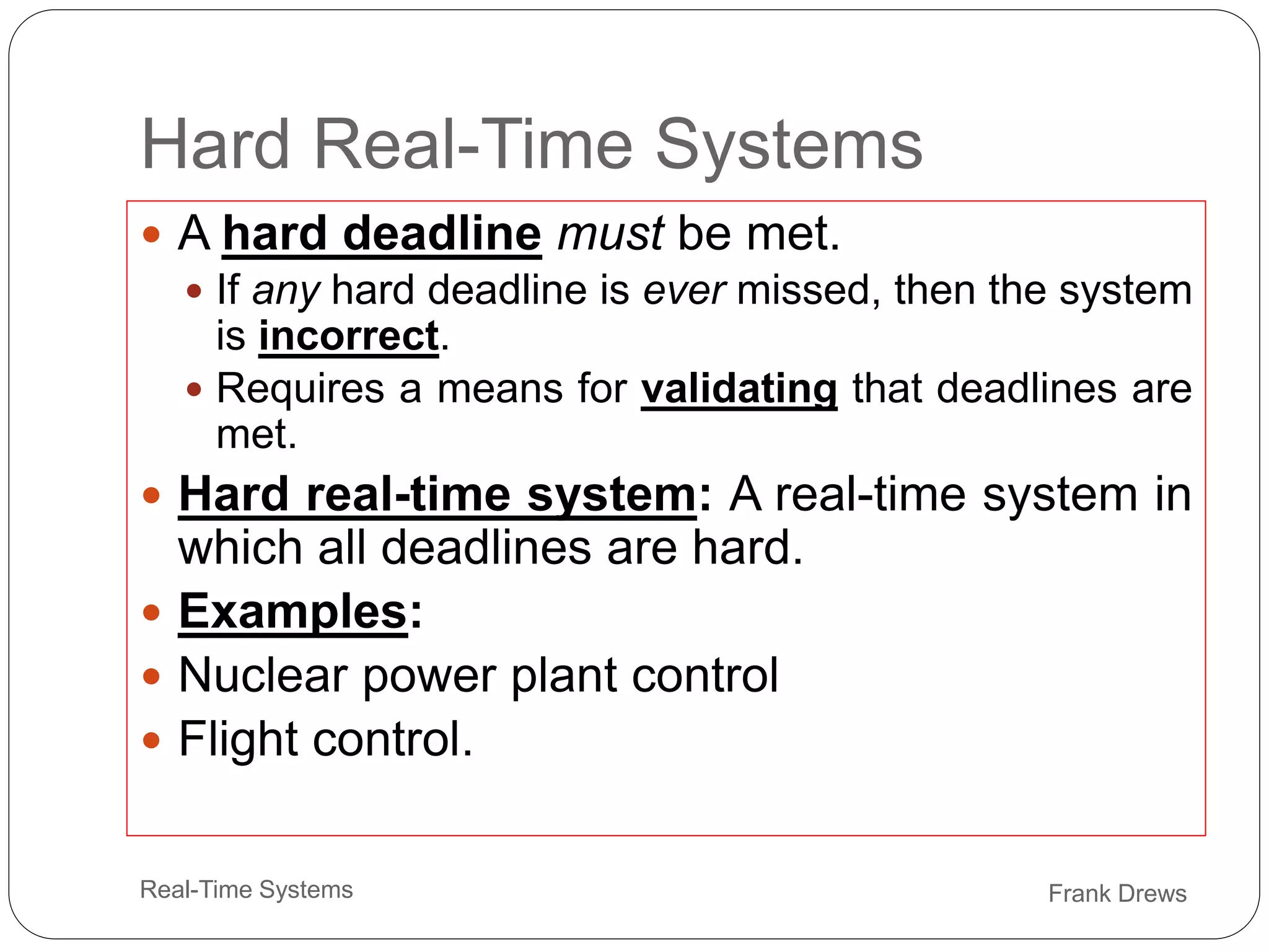
HardReal-Time Systems
A hard deadline must be met.
If any hard deadline is ever missed, then the system
is incorrect.
Requires a means for validating that deadlines are
met.
Hard real-time system: A real-time system in
which all deadlines are hard.
Examples:
Nuclear power plant control
Flight control.
20.
23
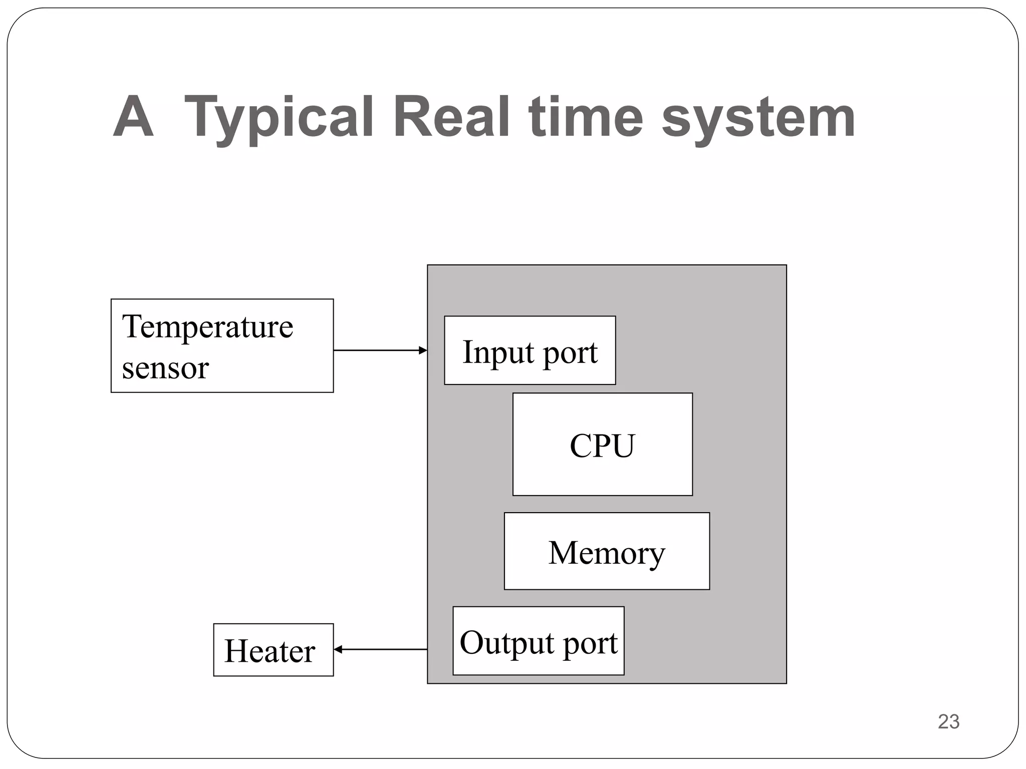
A Typical Realtime system
Temperature
sensor
CPU
Memory
Input port
Output port
Heater
21.
Frank Drews
Real-Time Systems
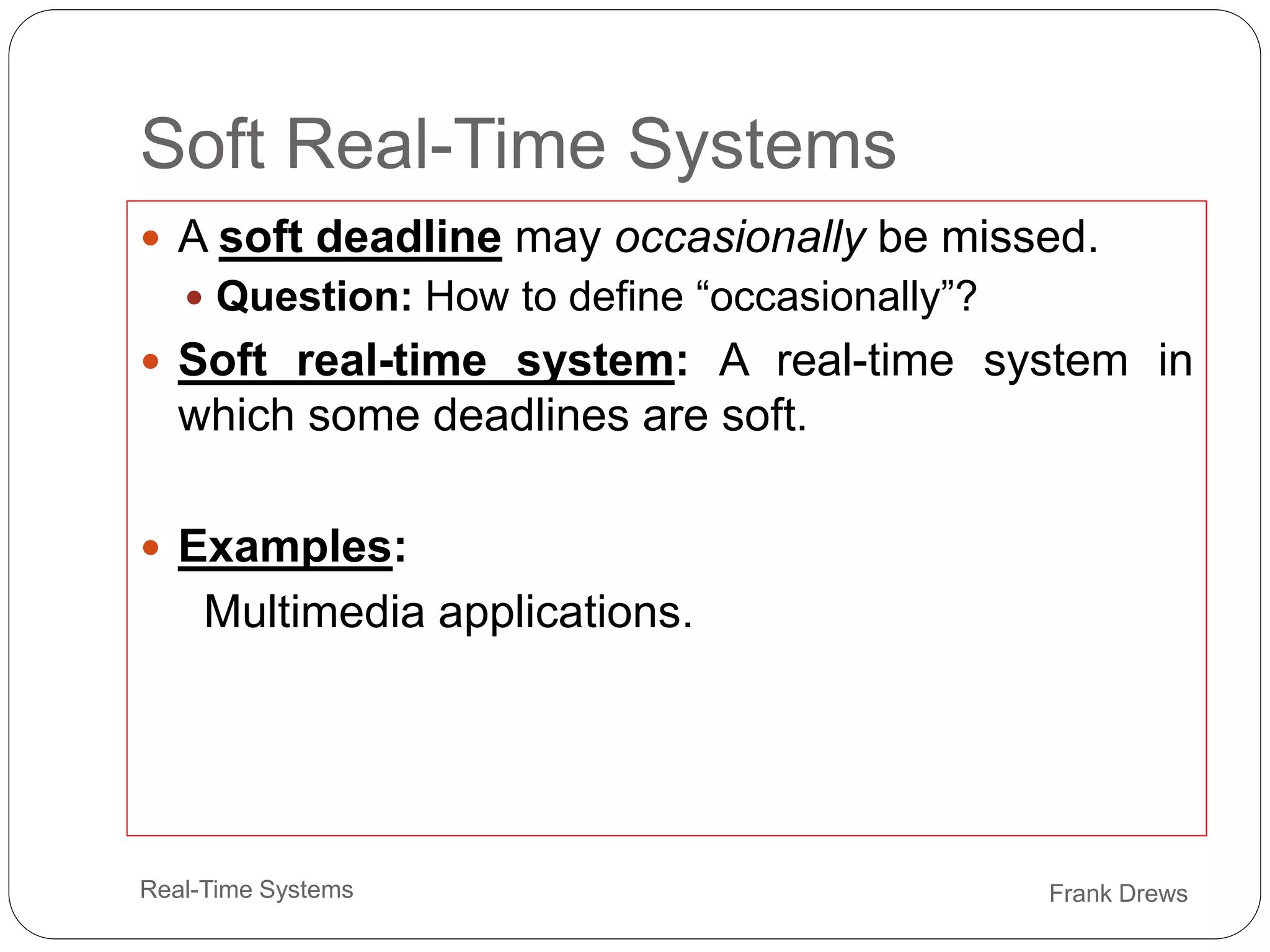
SoftReal-Time Systems
A soft deadline may occasionally be missed.
Question: How to define “occasionally”?
Soft real-time system: A real-time system in
which some deadlines are soft.
Examples:
Multimedia applications.
22.
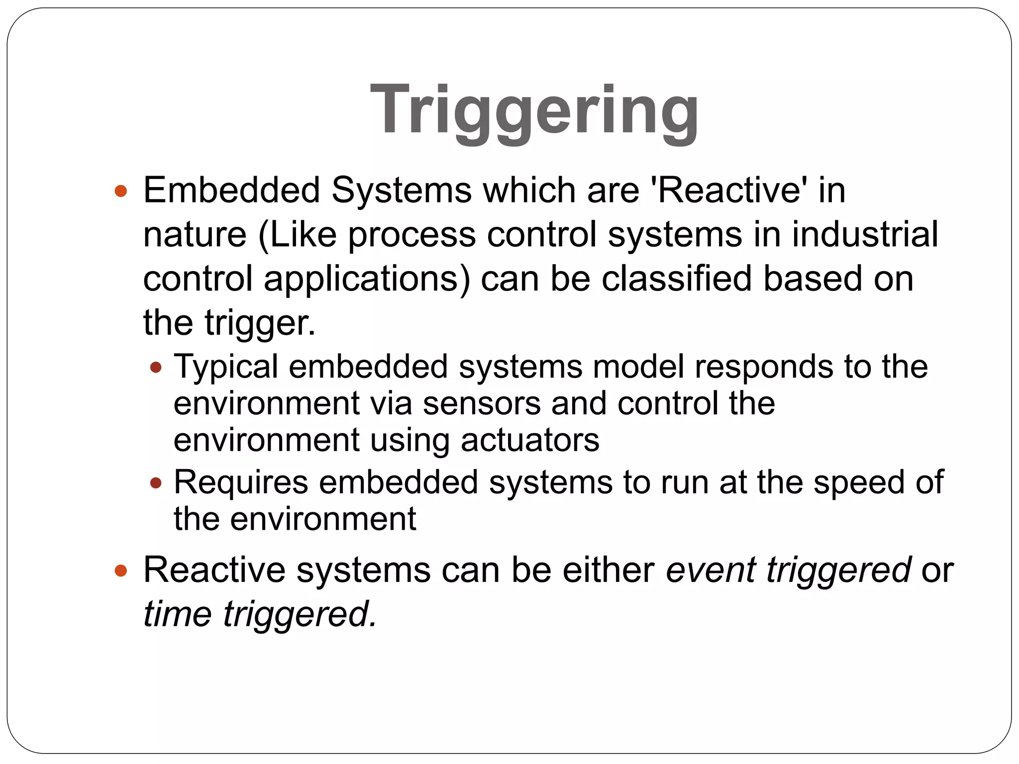
Triggering
Embedded Systemswhich are 'Reactive' in
nature (Like process control systems in industrial
control applications) can be classified based on
the trigger.
Typical embedded systems model responds to the
environment via sensors and control the
environment using actuators
Requires embedded systems to run at the speed of
the environment
Reactive systems can be either event triggered or
time triggered.
23.
26
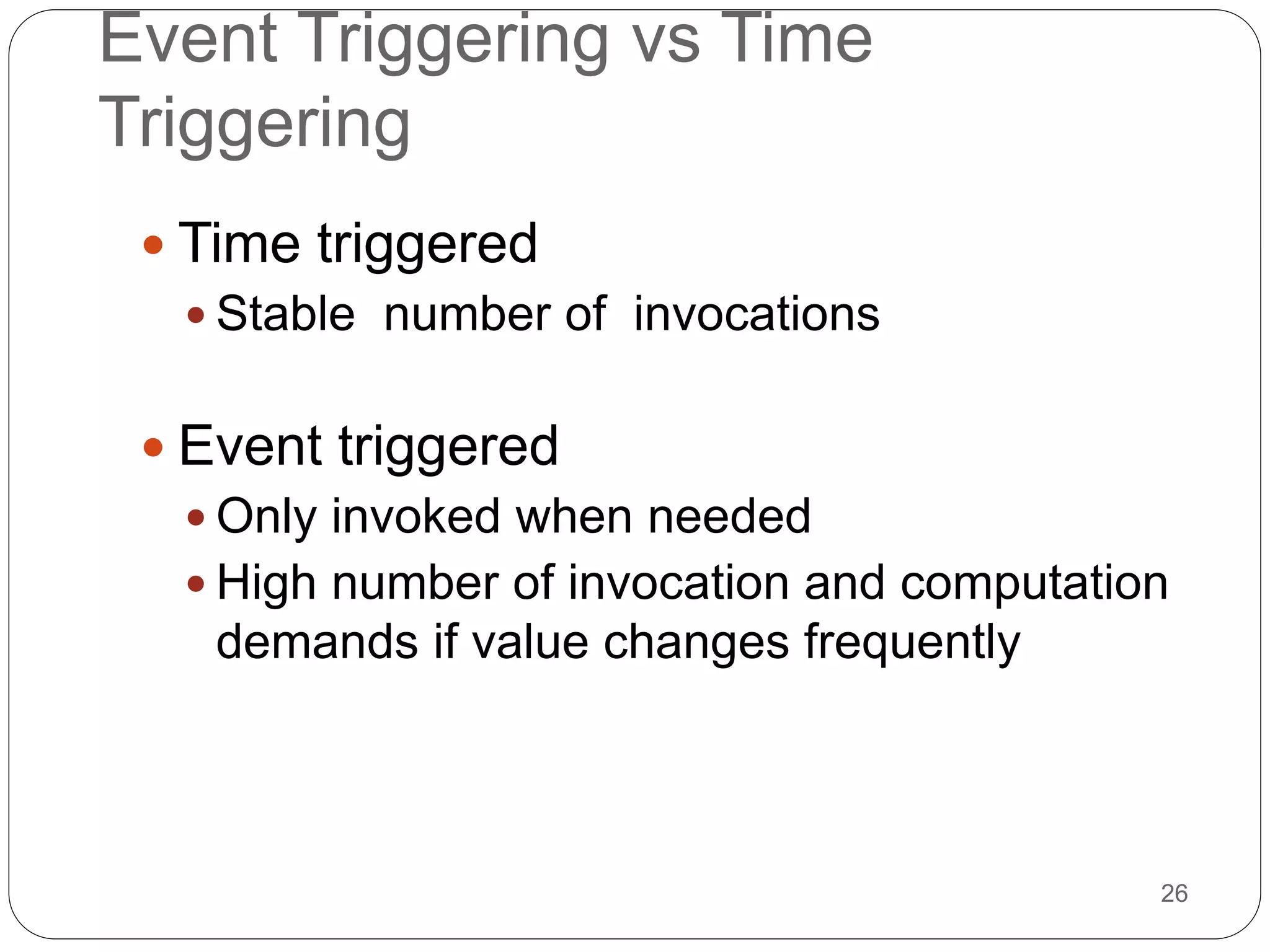
Event Triggering vsTime
Triggering
Time triggered
Stable number of invocations
Event triggered
Only invoked when needed
High number of invocation and computation
demands if value changes frequently
24.
27
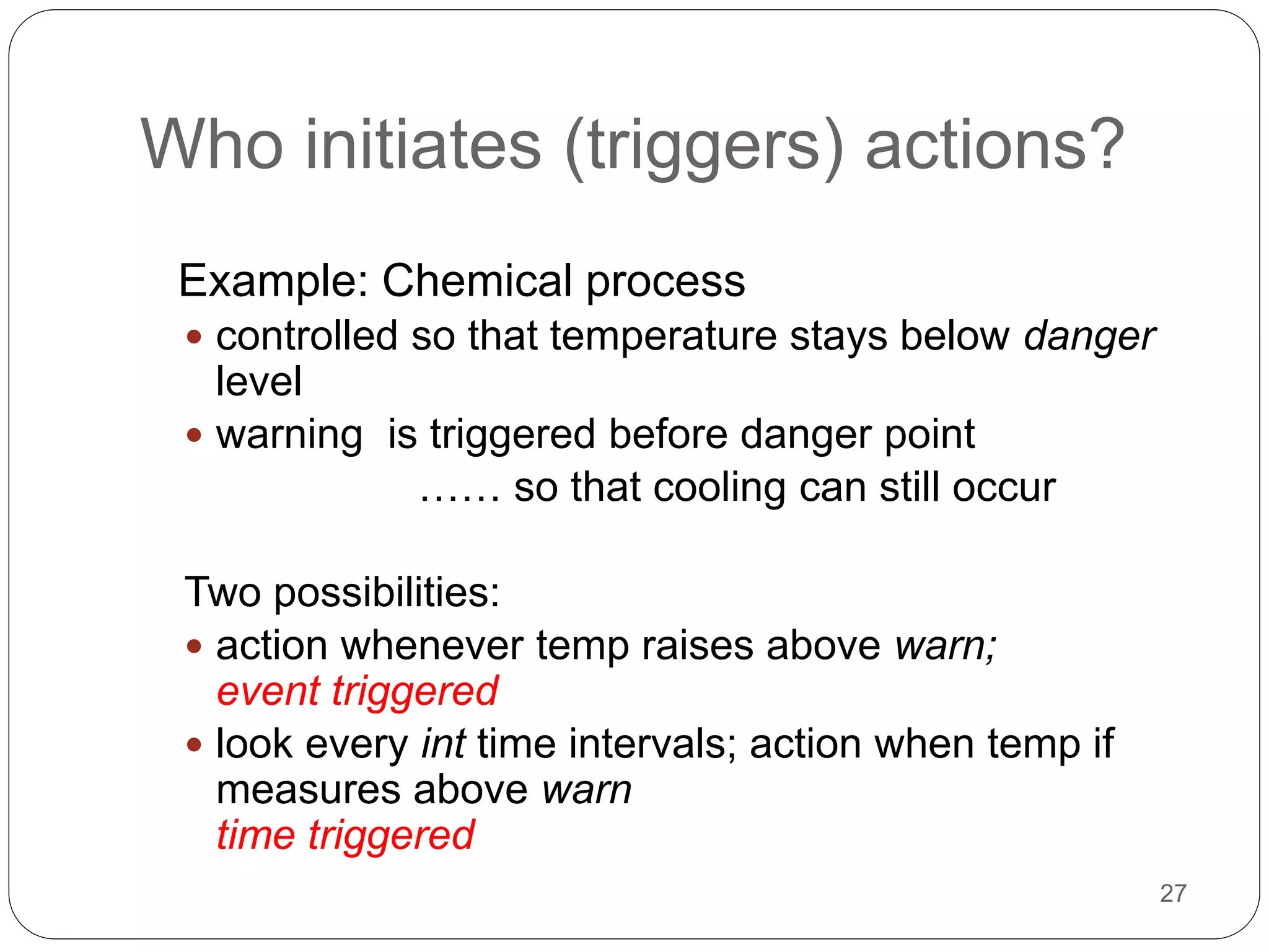
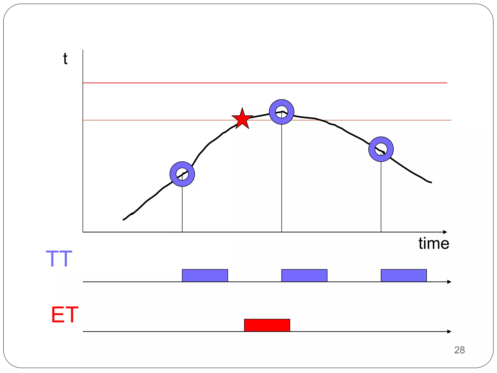
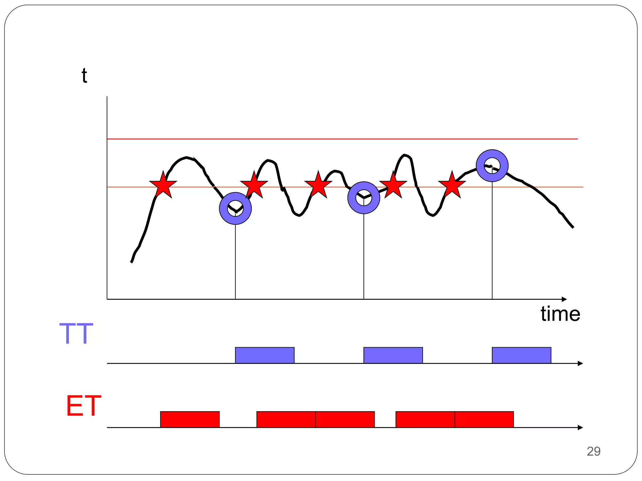
Who initiates (triggers)actions?
Example: Chemical process
controlled so that temperature stays below danger
level
warning is triggered before danger point
…… so that cooling can still occur
Two possibilities:
action whenever temp raises above warn;
event triggered
look every int time intervals; action when temp if
measures above warn
time triggered
Purpose of embeddedsystems
• Each embedded system is designed to serve
the purpose of any one or a combination of
the following tasks:
1. Data collection / Storage / Representations
2. Data communication
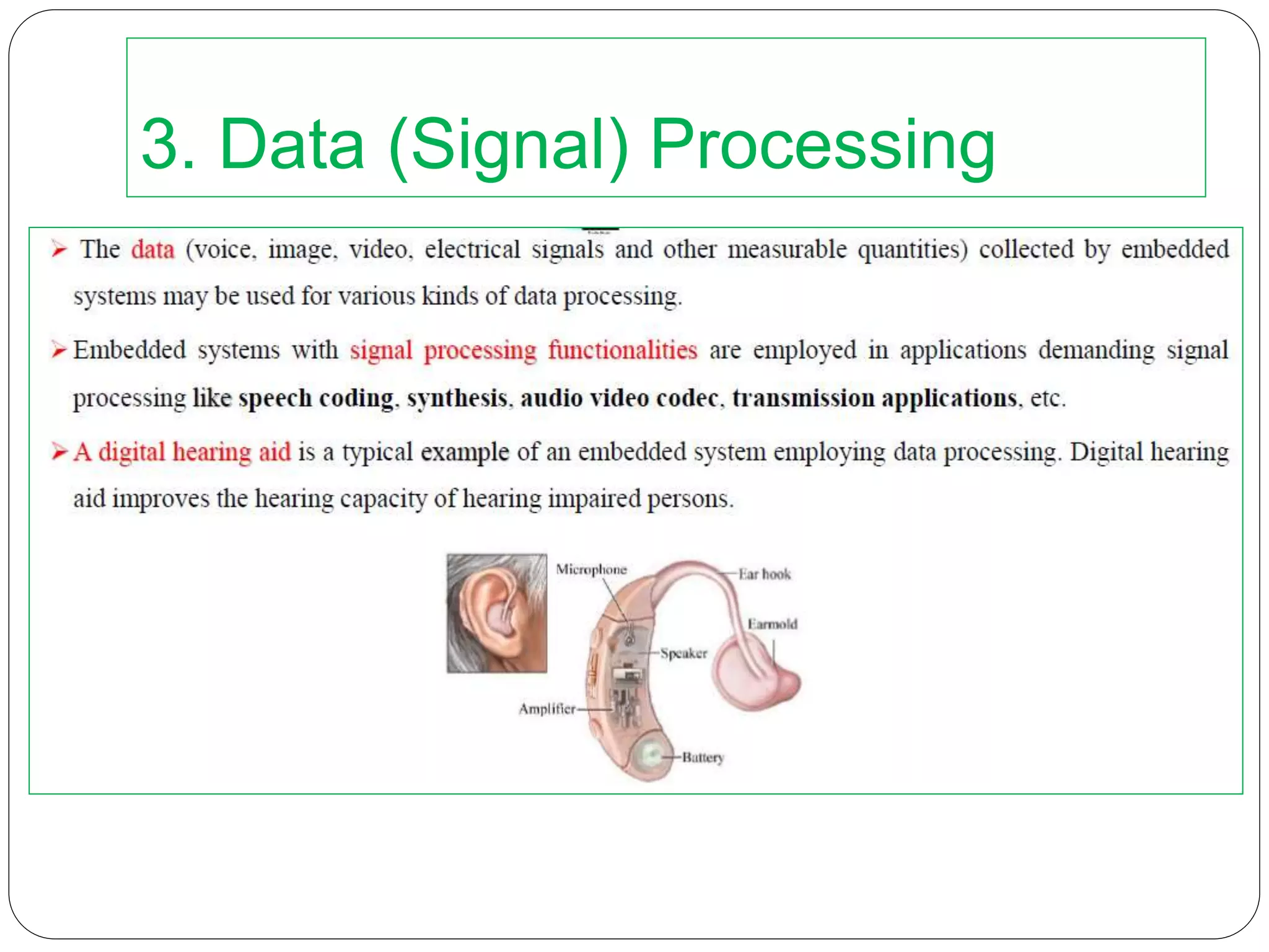
3. Data (signal) processing
4. Monitoring
5. Control
6. Application specific user interfaces
28.
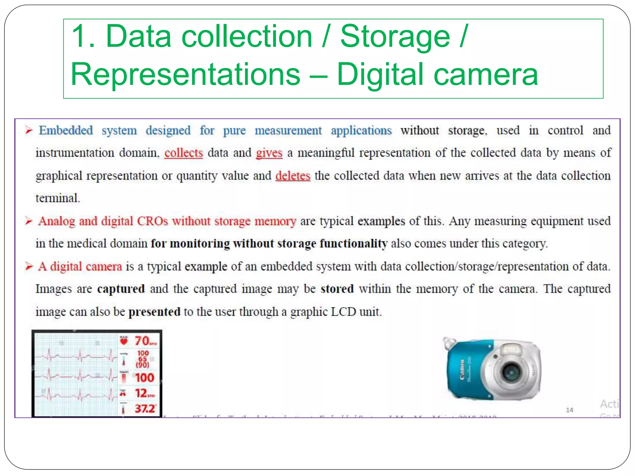
1. Data collection/ Storage /
Representations – Digital camera
Acquisition of data from the external world
“data” – text, voice, image, video, electrical
signals, and any other measurable quantities
Data – Analog or digital
Representation of the collected data by visual
(LCD / LEDs) or audible means (Buzzer, alarms,
etc)
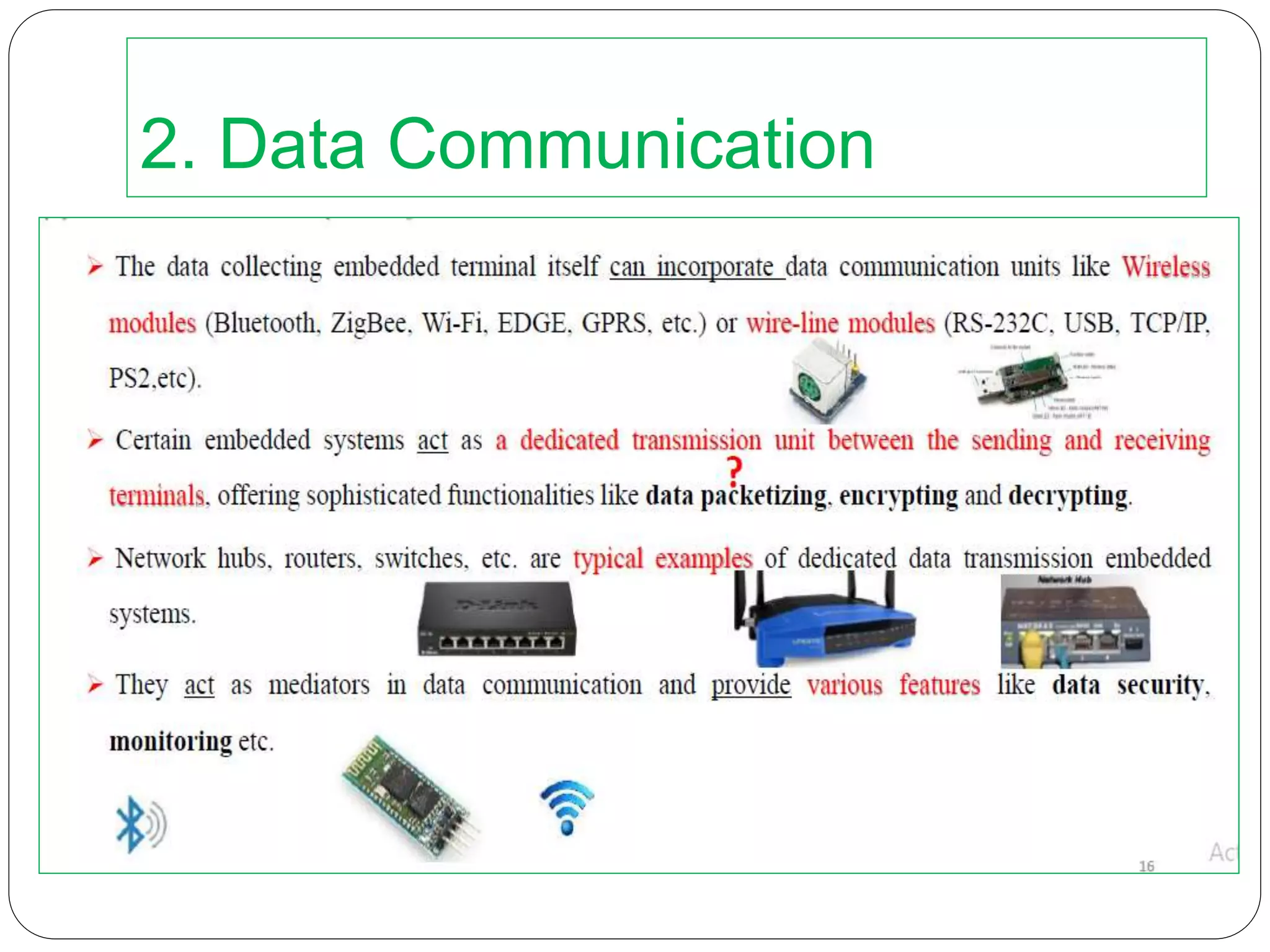
2. Data Communication
Embedded systems are used from simple home
networking systems to complex satellite
communications
Data collected by an embedded terminal may
require transferring of the same to other system
located remotely
Wired / Wireless communication
Wireless modules : Bluetooth, ZigBee, Wi-fi,
EDGE, GPRS
Wired modules : RS 232 C, USB, TCP / IP, PS2
,etc
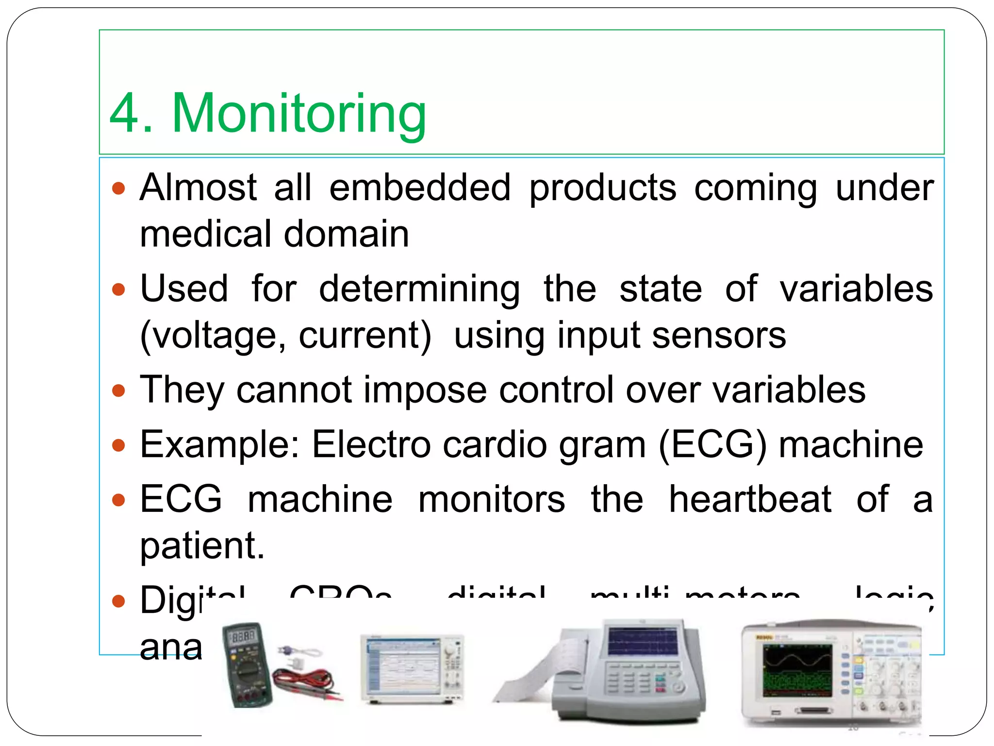
4. Monitoring
Almostall embedded products coming under
medical domain
Used for determining the state of variables
(voltage, current) using input sensors
They cannot impose control over variables
Example: Electro cardio gram (ECG) machine
ECG machine monitors the heartbeat of a
patient.
Digital CROs, digital multi-meters, logic
analysers, etc.
34.
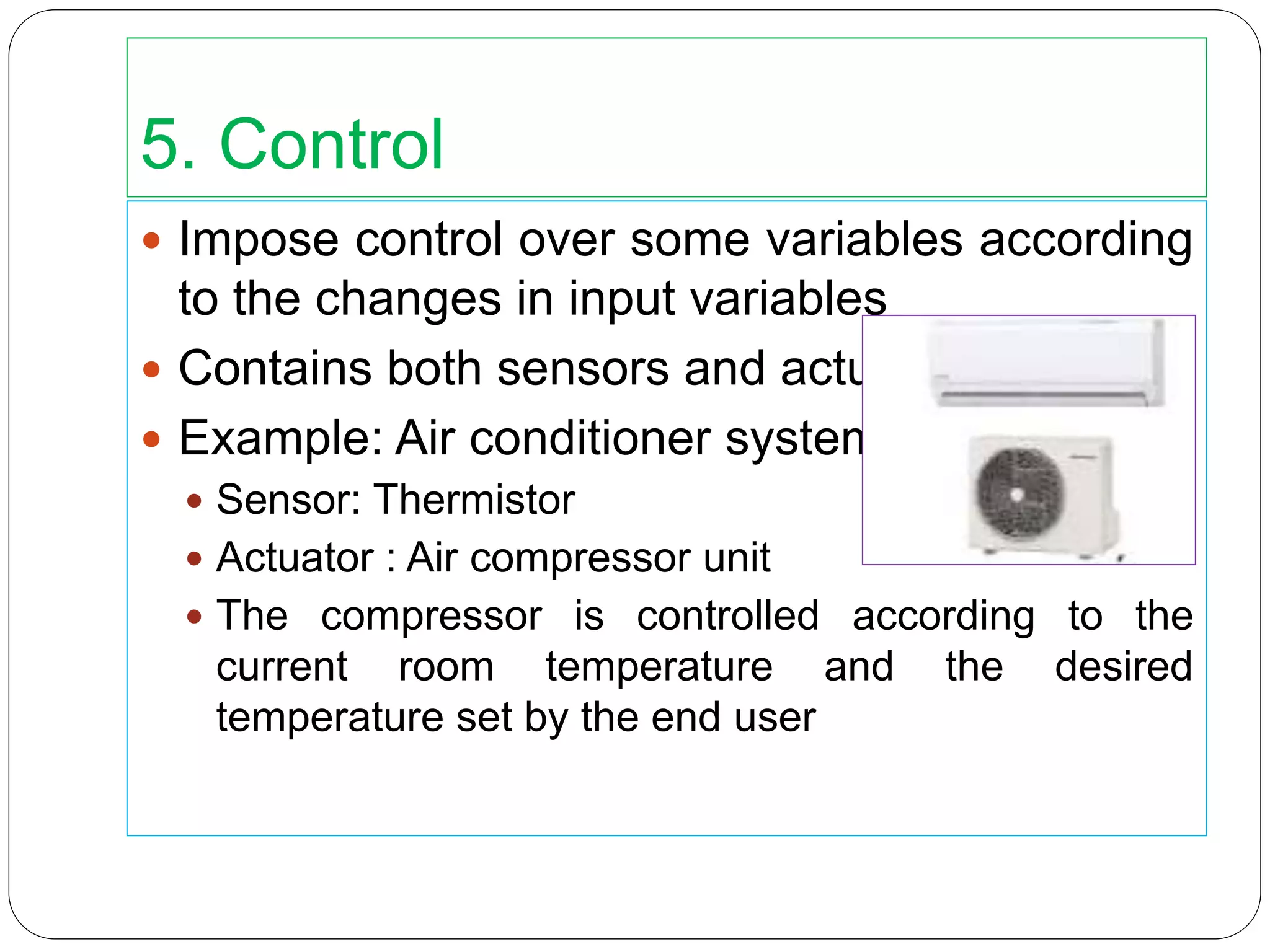
5. Control
Imposecontrol over some variables according
to the changes in input variables
Contains both sensors and actuators
Example: Air conditioner system
Sensor: Thermistor
Actuator : Air compressor unit
The compressor is controlled according to the
current room temperature and the desired
temperature set by the end user
35.
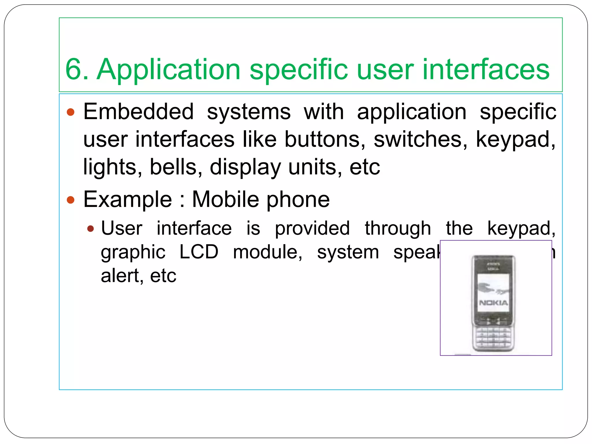
6. Application specificuser interfaces
Embedded systems with application specific
user interfaces like buttons, switches, keypad,
lights, bells, display units, etc
Example : Mobile phone
User interface is provided through the keypad,
graphic LCD module, system speaker, vibration
alert, etc
36.
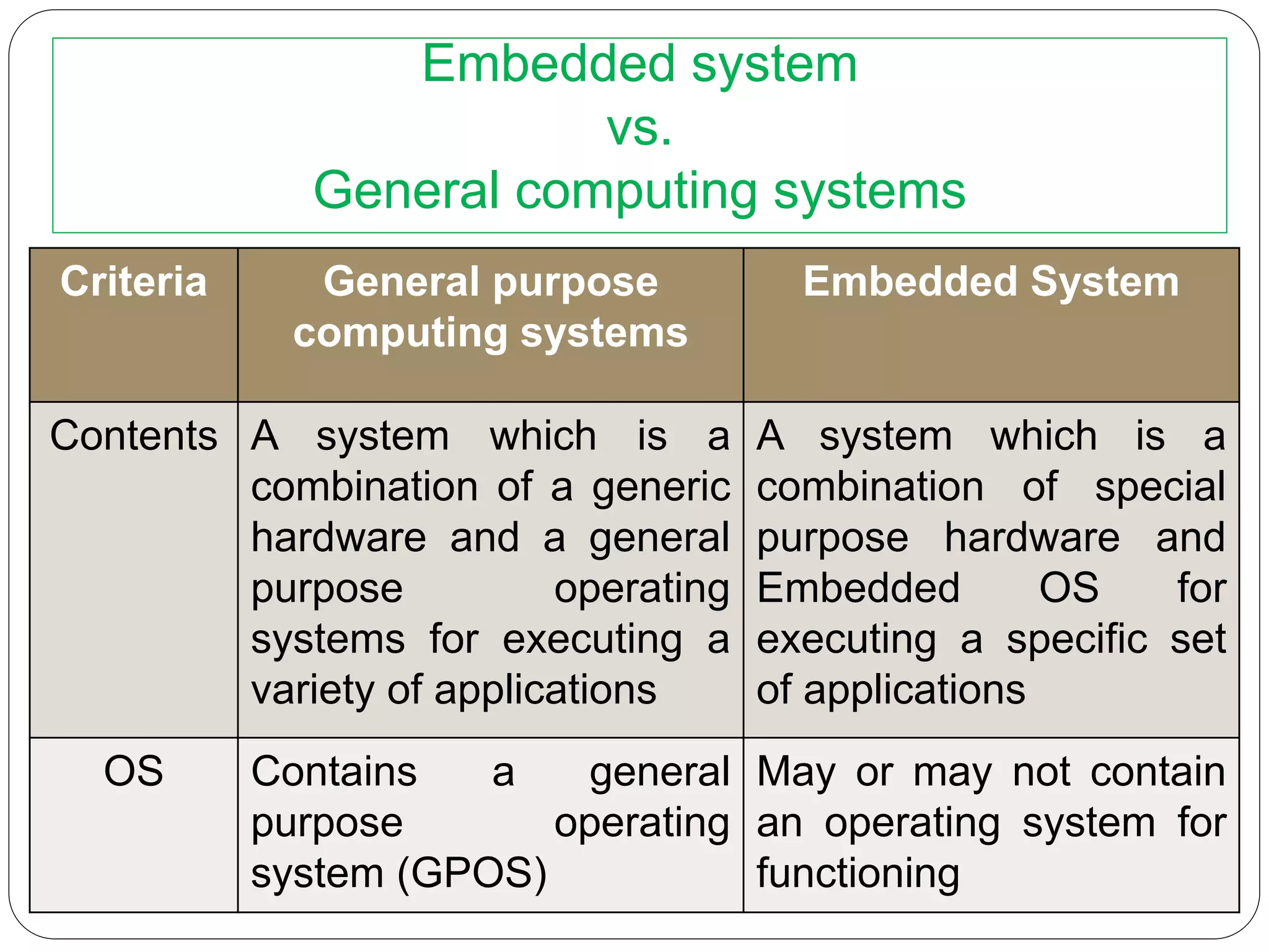
Embedded system
vs.
General computingsystems
Criteria General purpose
computing systems
Embedded System
Contents A system which is a
combination of a generic
hardware and a general
purpose operating
systems for executing a
variety of applications
A system which is a
combination of special
purpose hardware and
Embedded OS for
executing a specific set
of applications
OS Contains a general
purpose operating
system (GPOS)
May or may not contain
an operating system for
functioning
37.
Criteria General purpose
computingsystems
Embedded System
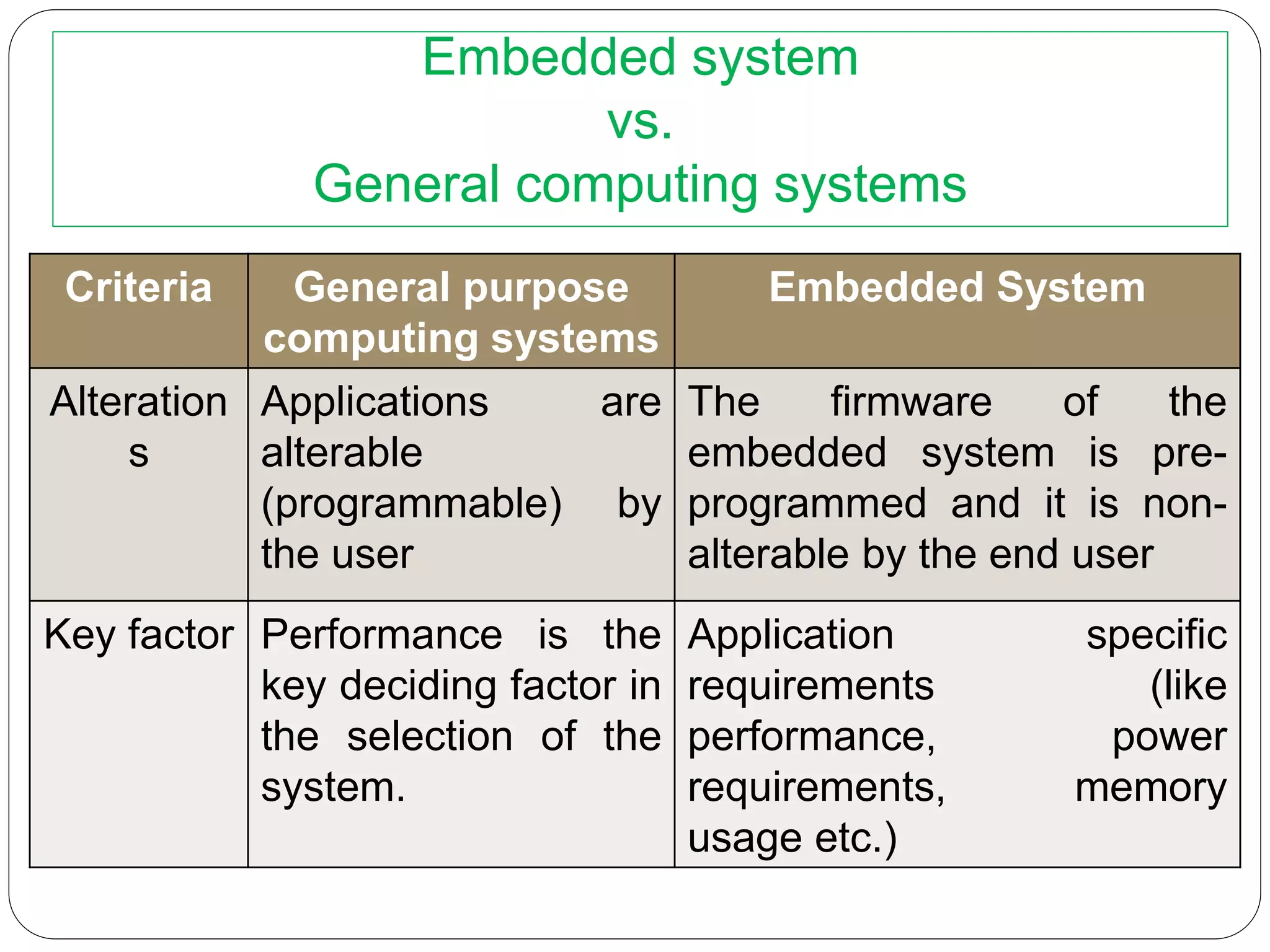
Alteration
s
Applications are
alterable
(programmable) by
the user
The firmware of the
embedded system is pre-
programmed and it is non-
alterable by the end user
Key factor Performance is the
key deciding factor in
the selection of the
system.
Application specific
requirements (like
performance, power
requirements, memory
usage etc.)
Embedded system
vs.
General computing systems
38.
Criteria General purpose
computing
systems
EmbeddedSystem
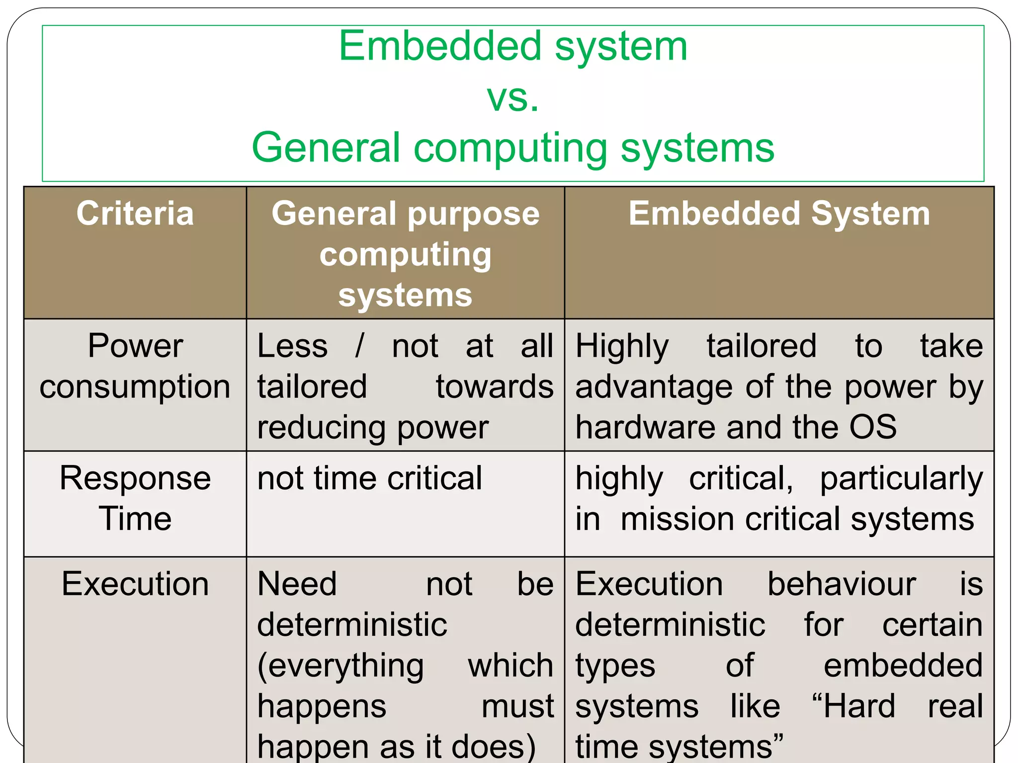
Power
consumption
Less / not at all
tailored towards
reducing power
Highly tailored to take
advantage of the power by
hardware and the OS
Response
Time
not time critical highly critical, particularly
in mission critical systems
Execution Need not be
deterministic
(everything which
happens must
happen as it does)
Execution behaviour is
deterministic for certain
types of embedded
systems like “Hard real
time systems”
Embedded system
vs.
General computing systems
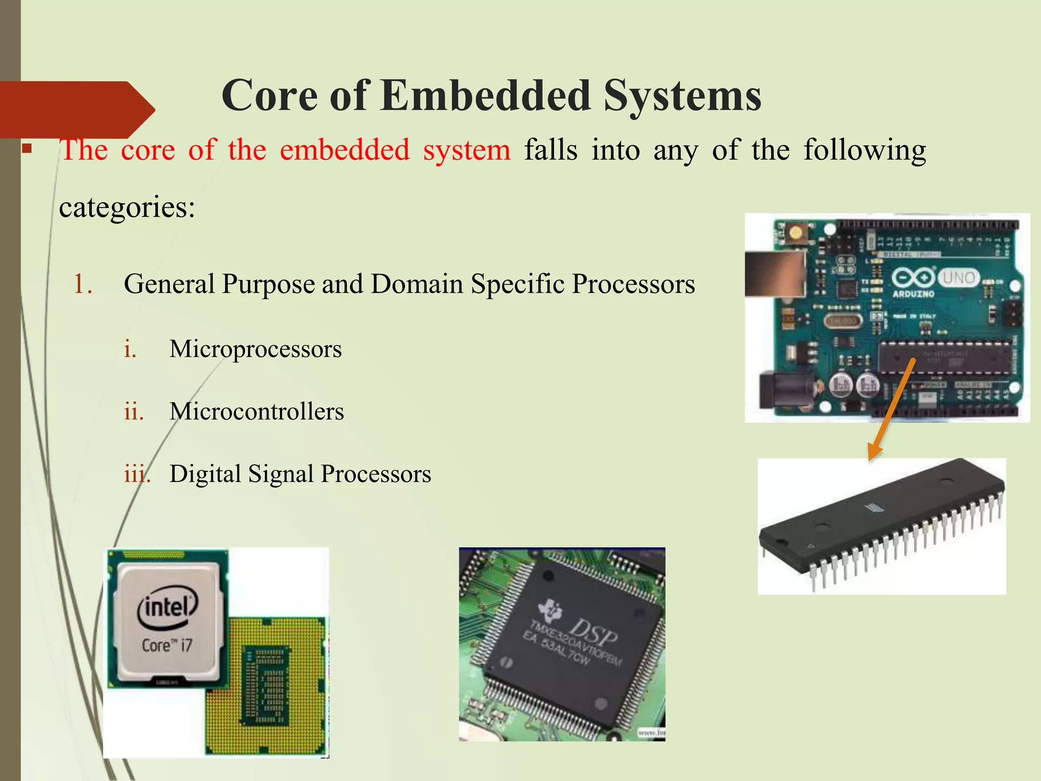
Core of EmbeddedSystems
The core of the embedded system falls into any of the following
categories:
1. General Purpose and Domain Specific Processors
i. Microprocessors
ii. Microcontrollers
iii. Digital Signal Processors
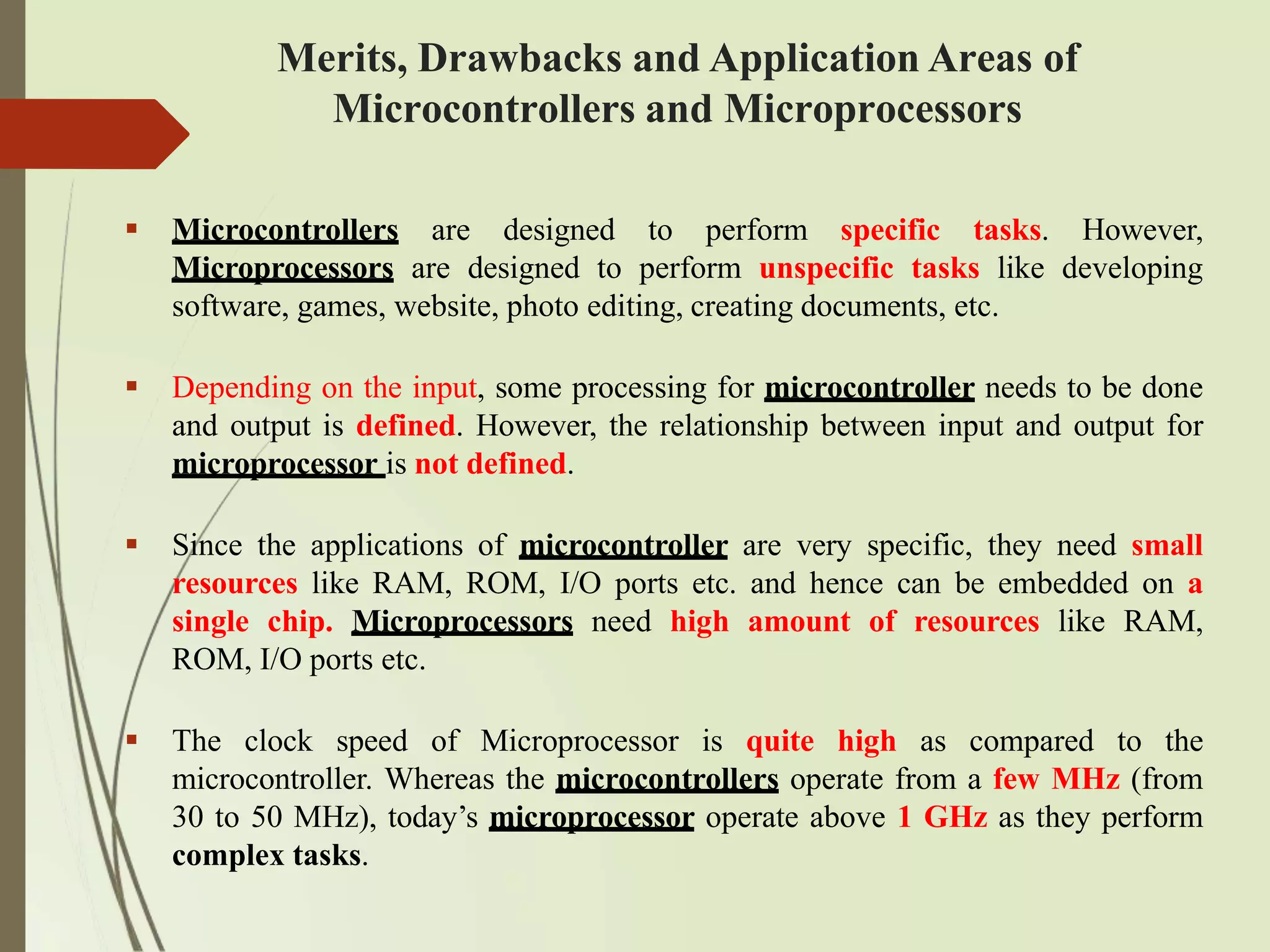
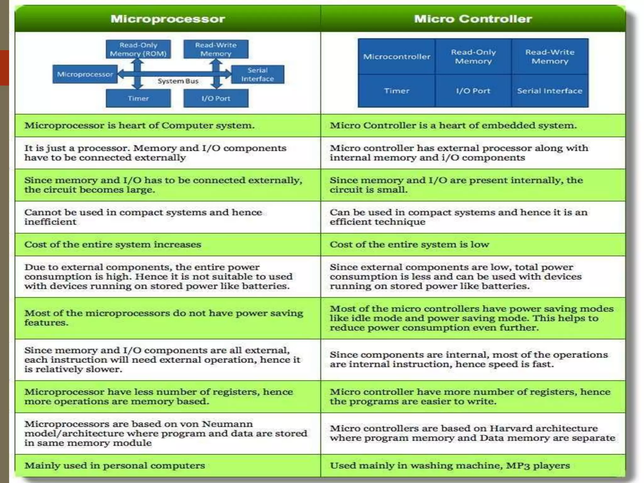
Microcontrollers aredesigned to perform specific tasks. However,
Microprocessors are designed to perform unspecific tasks like developing
software, games, website, photo editing, creating documents, etc.
Depending on the input, some processing for microcontroller needs to be done
and output is defined. However, the relationship between input and output for
microprocessor is not defined.
Since the applications of microcontroller are very specific, they need small
resources like RAM, ROM, I/O ports etc. and hence can be embedded on a
single chip. Microprocessors need high amount of resources like RAM,
ROM, I/O ports etc.
The clock speed of Microprocessor is quite high as compared to the
microcontroller. Whereas the microcontrollers operate from a few MHz (from
30 to 50 MHz), today’s microprocessor operate above 1 GHz as they perform
complex tasks.
Merits, Drawbacks and Application Areas of
Microcontrollers and Microprocessors
43.
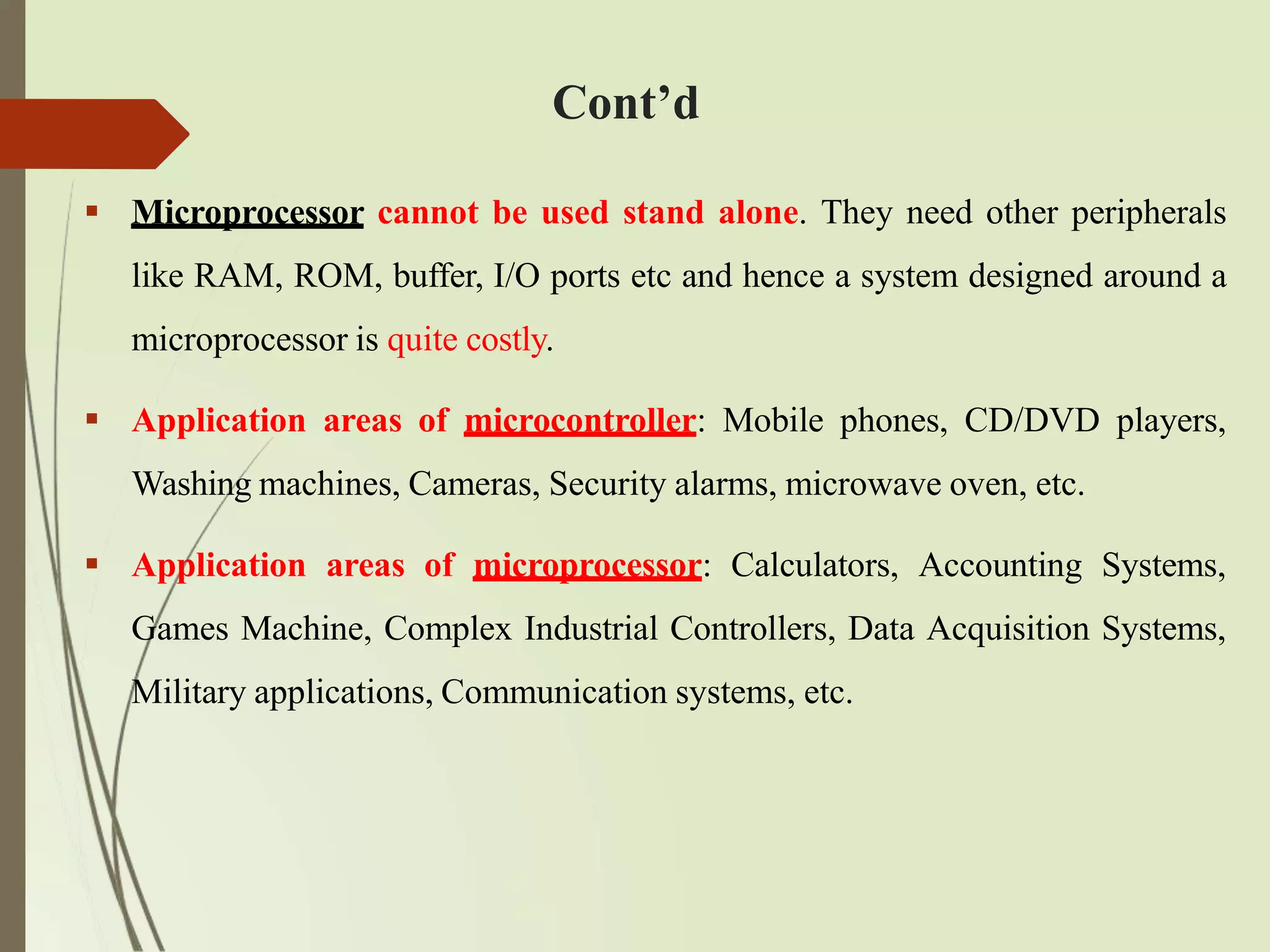
Microprocessor cannotbe used stand alone. They need other peripherals
like RAM, ROM, buffer, I/O ports etc and hence a system designed around a
microprocessor is quite costly.
Application areas of microcontroller: Mobile phones, CD/DVD players,
Washing machines, Cameras, Security alarms, microwave oven, etc.
Application areas of microprocessor: Calculators, Accounting Systems,
Games Machine, Complex Industrial Controllers, Data Acquisition Systems,
Military applications, Communication systems, etc.
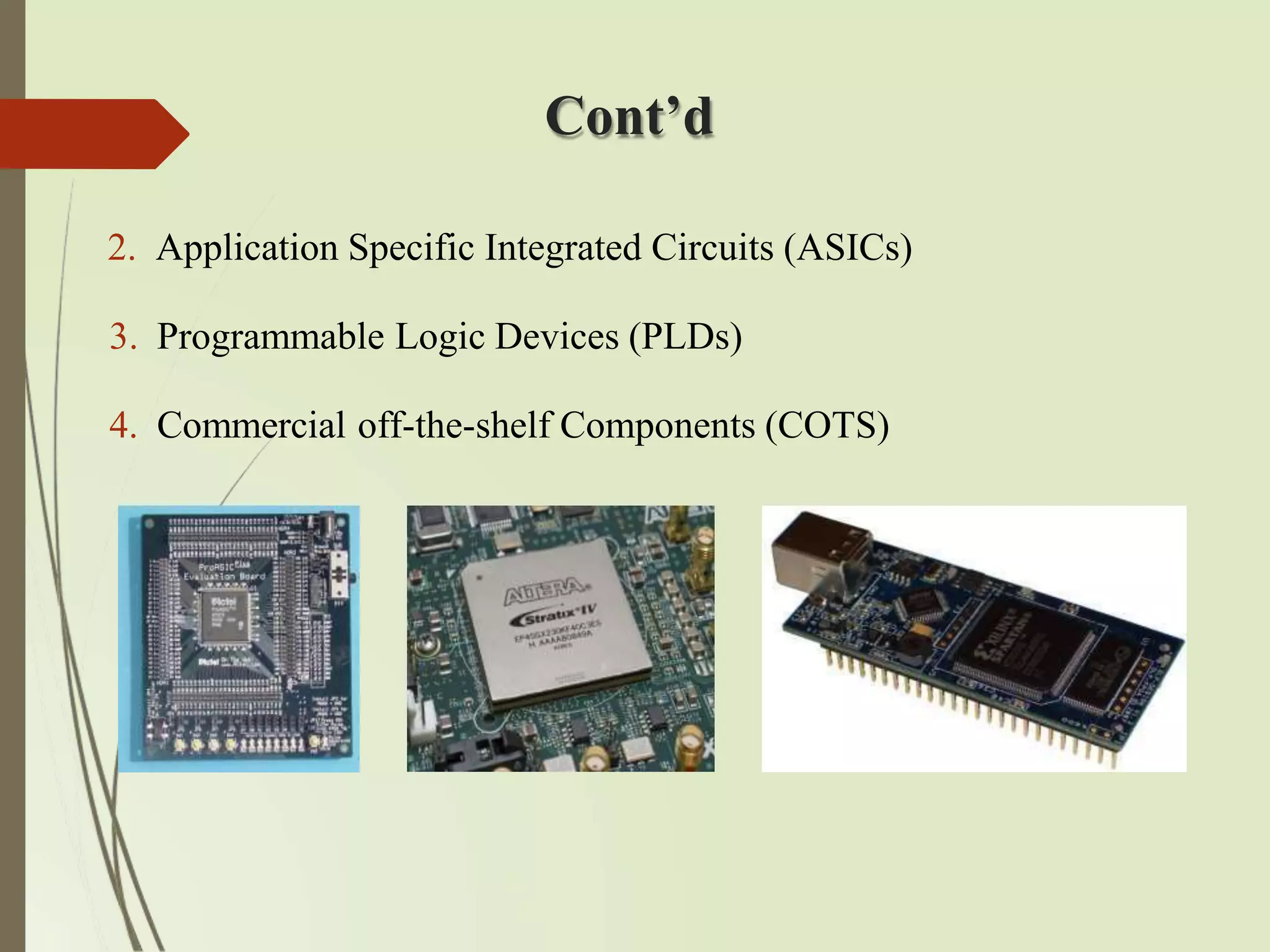
Cont’d
Digital Signal Processors
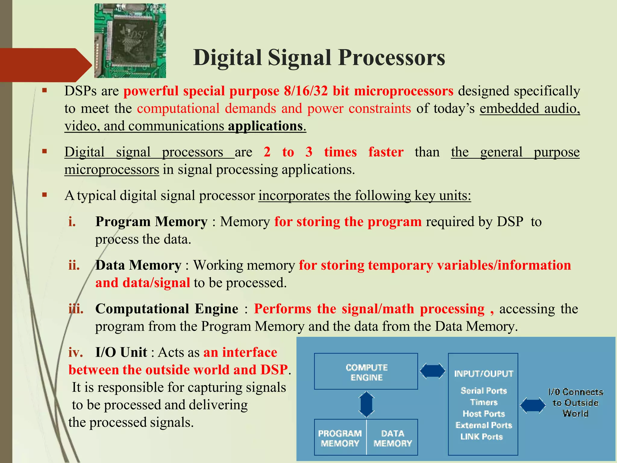
DSPs are powerful special purpose 8/16/32 bit microprocessors designed specifically
to meet the computational demands and power constraints of today’s embedded audio,
video, and communications applications.
Digital signal processors are 2 to 3 times faster than the general purpose
microprocessors in signal processing applications.
Atypical digital signal processor incorporates the following key units:
iii.
i. Program Memory : Memory for storing the program required by DSP to
process the data.
ii. Data Memory : Working memory for storing temporary variables/information
and data/signal to be processed.
Computational Engine : Performs the signal/math processing , accessing the
program from the Program Memory and the data from the Data Memory.
iv. I/O Unit : Acts as an interface
between the outside world and DSP.
It is responsible for capturing signals
to be processed and delivering
the processed signals.
48.
Cont’d
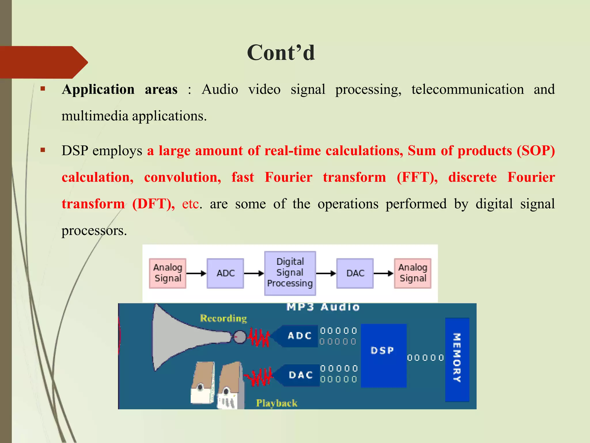
Application areas: Audio video signal processing, telecommunication and
multimedia applications.
DSP employs a large amount of real-time calculations, Sum of products (SOP)
calculation, convolution, fast Fourier transform (FFT), discrete Fourier
transform (DFT), etc. are some of the operations performed by digital signal
processors.
49.
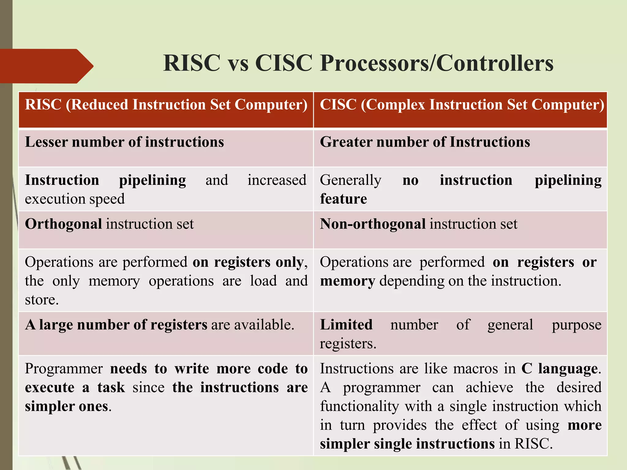
RISC vs CISCProcessors/Controllers
RISC (Reduced Instruction Set Computer) CISC (Complex Instruction Set Computer)
Lesser number of instructions Greater number of Instructions
Instruction pipelining
execution speed
and increased Generally
feature
no instruction pipelining
Orthogonal instruction set Non-orthogonal instruction set
Operations are performed on registers only,
the only memory operations are load and
store.
Operations are performed on registers or
memory depending on the instruction.
A large number of registers are available. Limited
registers.
number of general purpose
Programmer needs to write more code to
execute a task since the instructions are
simpler ones.
Instructions are like macros in C language.
A programmer can achieve the desired
functionality with a single instruction which
in turn provides the effect of using more
simpler single instructions in RISC.
50.
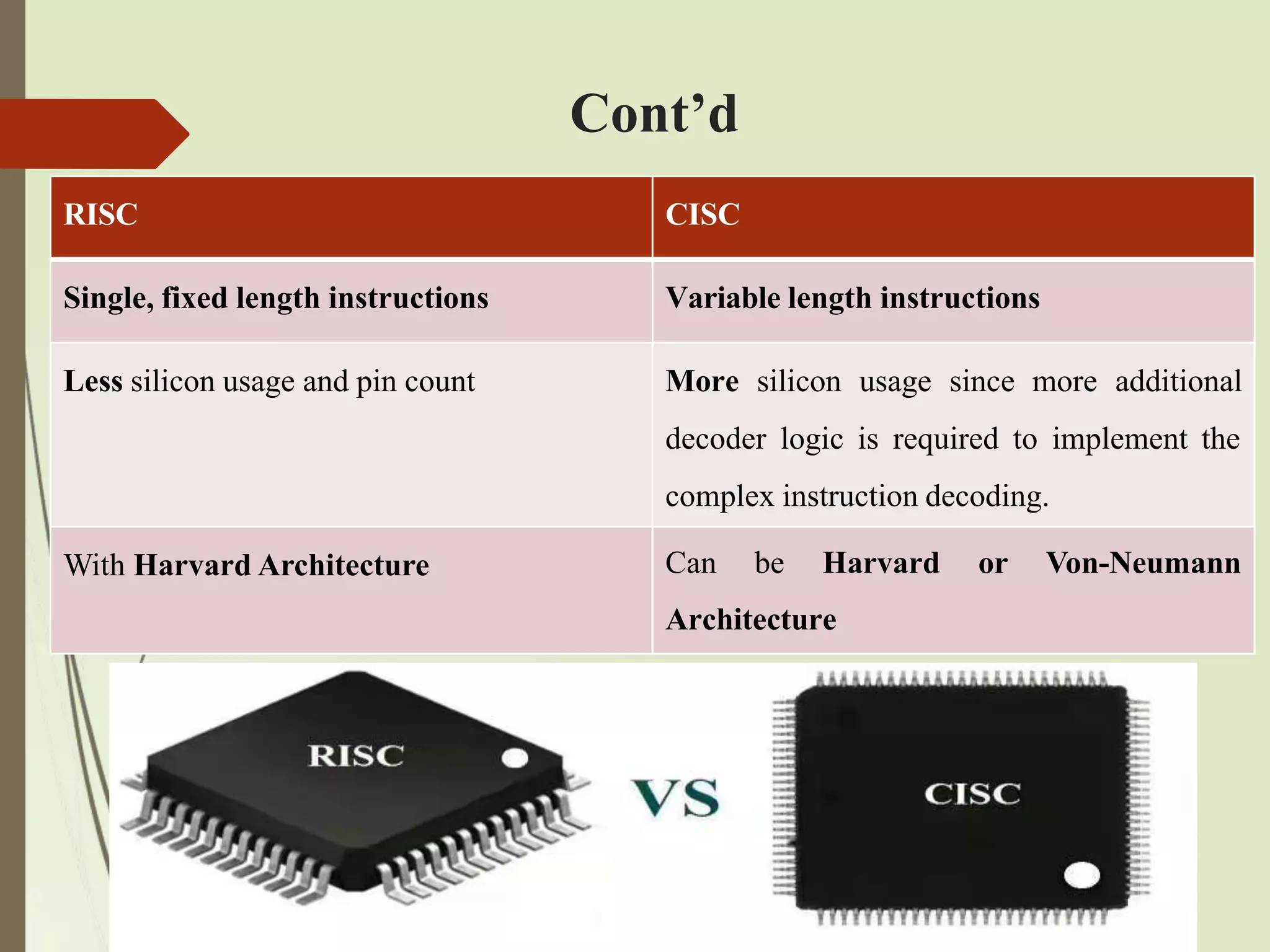
Cont’d
RISC CISC
Single, fixedlength instructions Variable length instructions
Less silicon usage and pin count More silicon usage since more additional
decoder logic is required to implement the
complex instruction decoding.
With Harvard Architecture Can be Harvard or Von-Neumann
Architecture
51.
Big-Endian vs. Little-EndianProcessors/Controllers
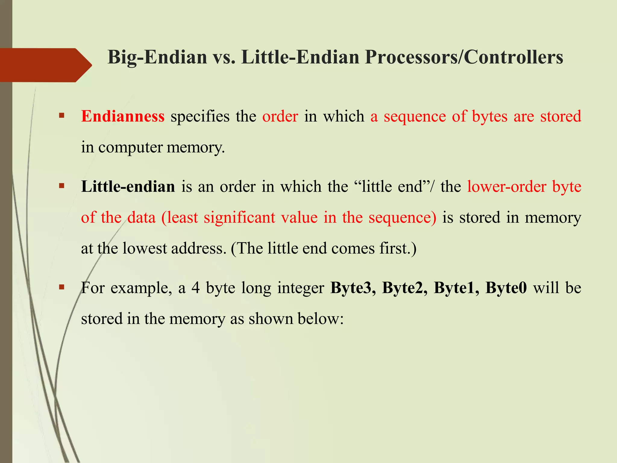
Endianness specifies the order in which a sequence of bytes are stored
in computer memory.
Little-endian is an order in which the “little end”/ the lower-order byte
of the data (least significant value in the sequence) is stored in memory
at the lowest address. (The little end comes first.)
For example, a 4 byte long integer Byte3, Byte2, Byte1, Byte0 will be
stored in the memory as shown below:
52.
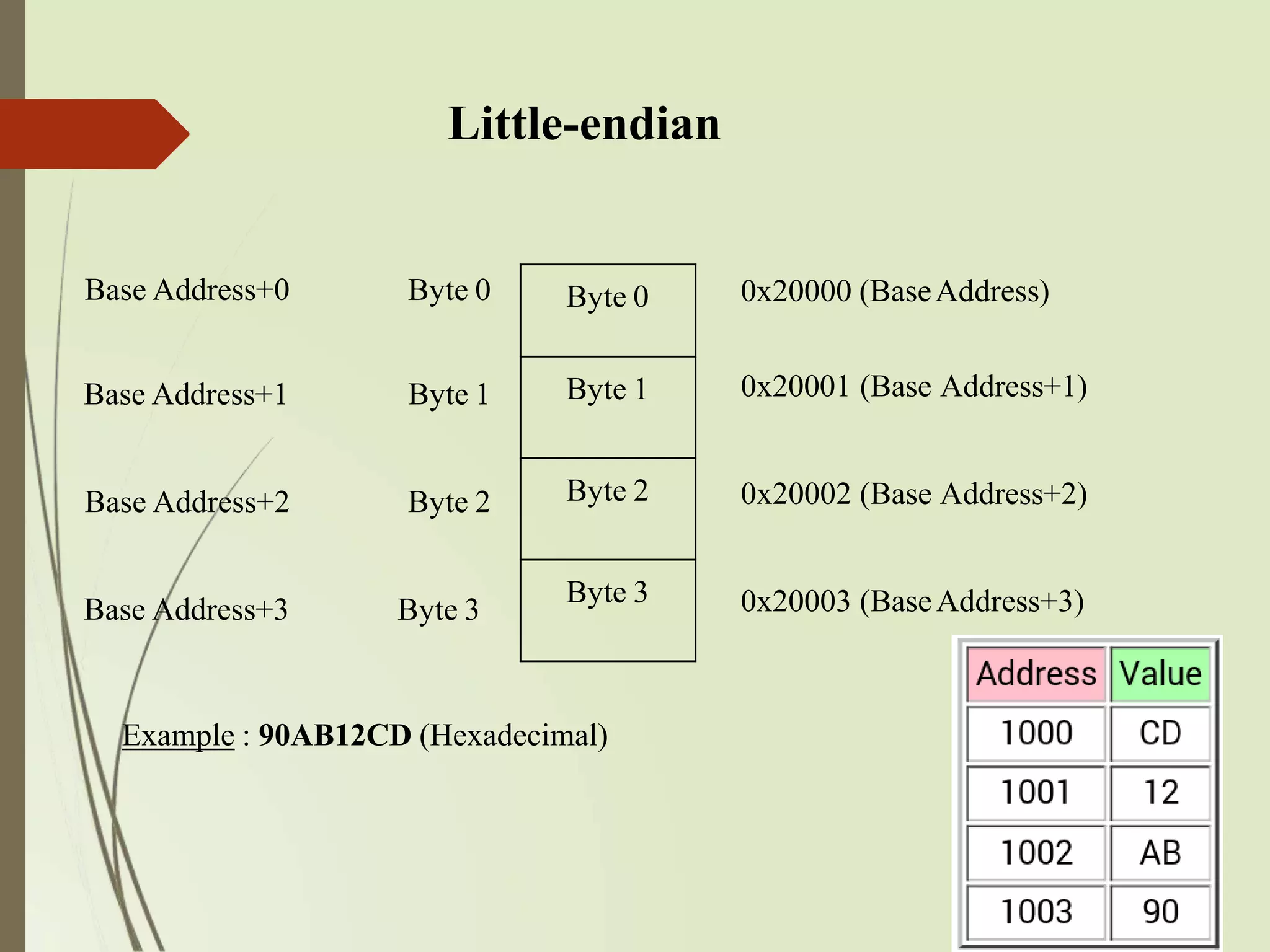
Little-endian
Base Address+0 Byte0 Byte 0
Base Address+1 Byte 1 Byte 1
Base Address+2 Byte 2 Byte 2
Base Address+3 Byte 3
Byte 3
0x20000 (BaseAddress)
0x20001 (Base Address+1)
0x20002 (Base Address+2)
0x20003 (BaseAddress+3)
Example : 90AB12CD (Hexadecimal)
53.
Big-endian
Big-endian isan order in which the “big end” / the higher-order byte of
the data (most significant value in sequence) is stored in memory at the
lowest address. (The big end comes first.)
For example, a 4 byte long integer Byte3, Byte2, Byte1, Byte0 will be
stored in the memory as shown below:
54.
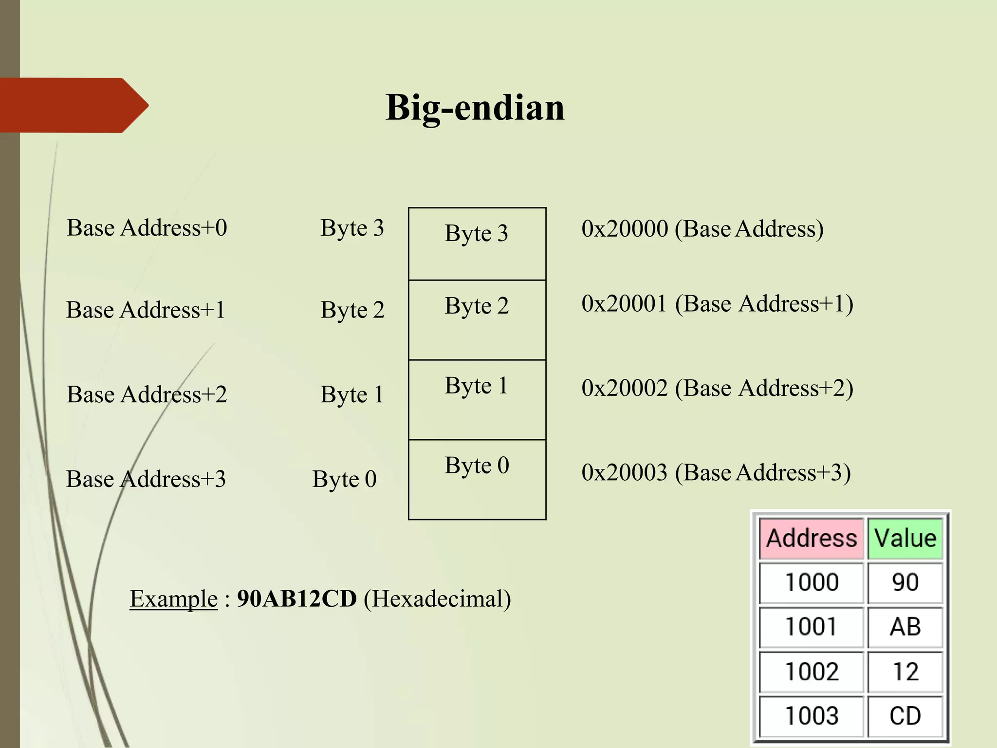
Big-endian
Base Address+0 Byte3 Byte 3
Base Address+1 Byte 2 Byte 2
Base Address+2 Byte 1 Byte 1
Base Address+3 Byte 0
Byte 0
0x20000 (BaseAddress)
0x20001 (Base Address+1)
0x20002 (Base Address+2)
0x20003 (BaseAddress+3)
Example : 90AB12CD (Hexadecimal)
55.
2.2 Memory
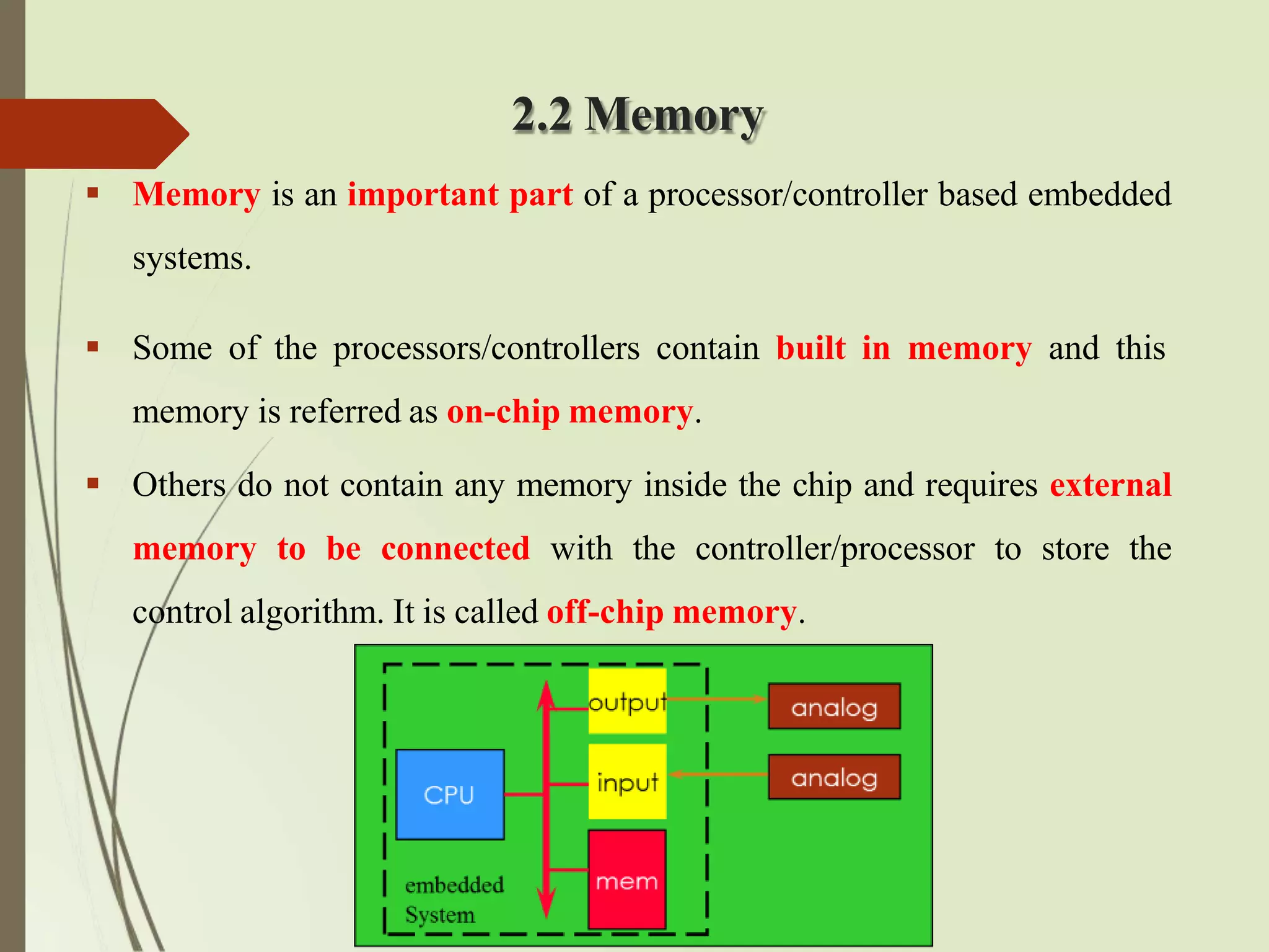
Memoryis an important part of a processor/controller based embedded
systems.
Some of the processors/controllers contain built in memory and this
memory is referred as on-chip memory.
Others do not contain any memory inside the chip and requires external
memory to be connected with the controller/processor to store the
control algorithm. It is called off-chip memory.
56.
Cont’d
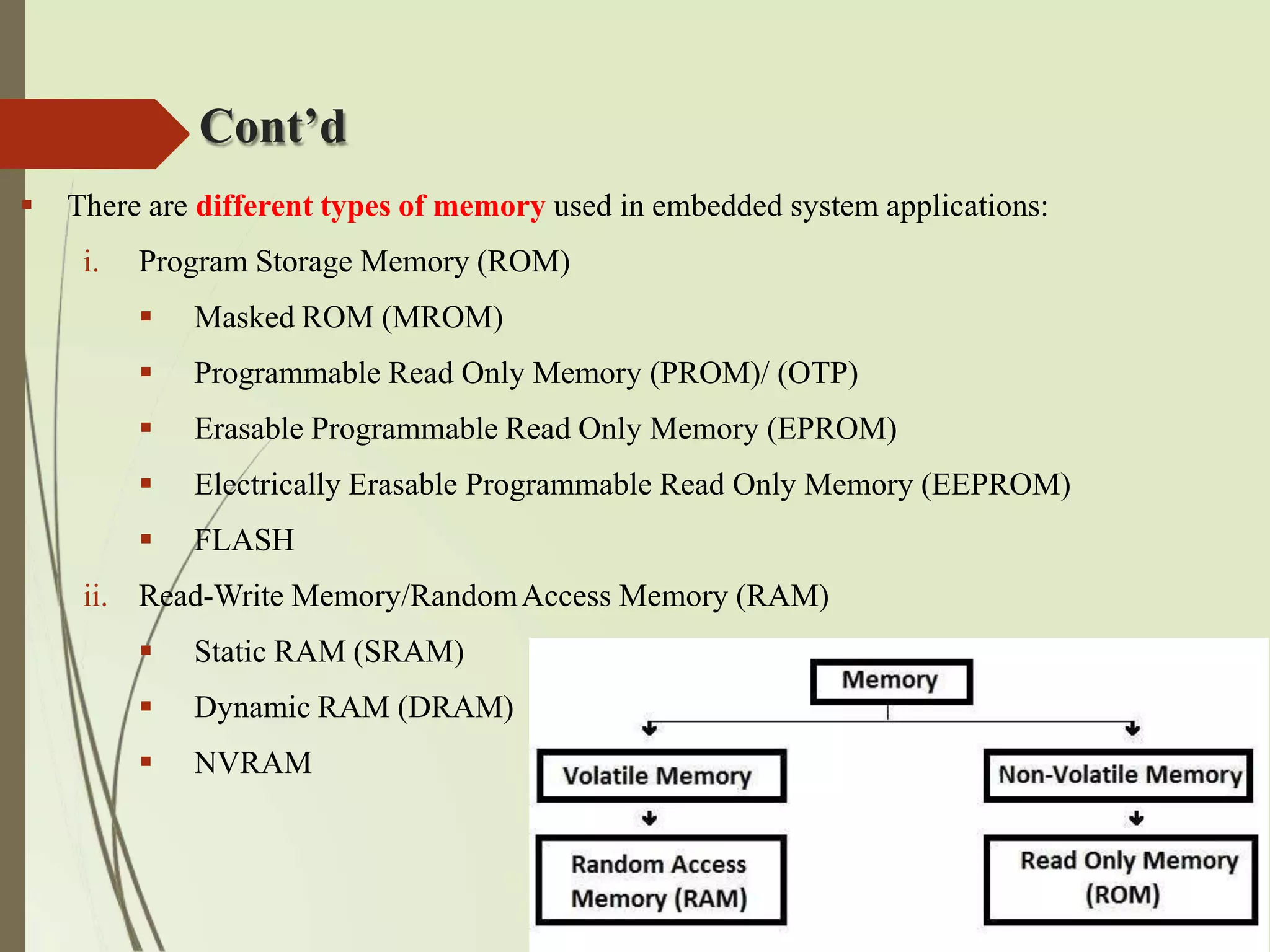
There aredifferent types of memory used in embedded system applications:
i. Program Storage Memory (ROM)
Masked ROM (MROM)
Programmable Read Only Memory (PROM)/ (OTP)
Erasable Programmable Read Only Memory (EPROM)
Electrically Erasable Programmable Read Only Memory (EEPROM)
FLASH
ii. Read-Write Memory/RandomAccess Memory (RAM)
Static RAM (SRAM)
Dynamic RAM (DRAM)
NVRAM
57.
Classification of ROM
Mask ROM : Masked ROM is a static ROM which comes programmed into an integrated
circuit by its manufacturer. Masked ROM makes use of the hardwired technology for
storing data. It is a good candidate for storing the embedded firmware for low cost
embedded devices. The primary advantage of this is low cost for high volume production.
The limitation with MROM based firmware storage is the inability to modify the device
firmware against firmware upgrades. They are used in network operating systems, server
operating systems, storing of fonts for laser printers, sound data in electronic musical
instruments.
PROM/ OTP : Unlike MROM, One Time Programmable Memory (OTP) or PROM is not
pre-programmed by the manufacturer. The end user is responsible for programming
these devices. They have several different applications, including cell phones, video game
consoles, RFID tags, medical devices, and other electronics.
58.
Cont’d
EPROM :EPROM gives the flexibility to re-program the same chip. EPROM stores the bit
information by charging the floating gate of an FET and contains a quartz crystal window for
erasing the stored information. Even though the EPROM chip is flexible in terms of re-
programmability, it needs to be taken out of the circuit board and put in a UV eraser device for 20 to
30 minutes. So it is a tedious and time-consuming process.
EEPROM : The information contained in the EEPROM memory can be altered by using electrical
signal at the register/Byte level. They can be erased and reprogrammed in-circuit. These chips
include a chip erase mode and in this mode they can be erased in a few milliseconds. It provides
greater flexibility for system design. The only limitation is their capacity is limited when
compared with the standard ROM (a few kilobytes). It is used for storing the computer system
BIOS.
59.
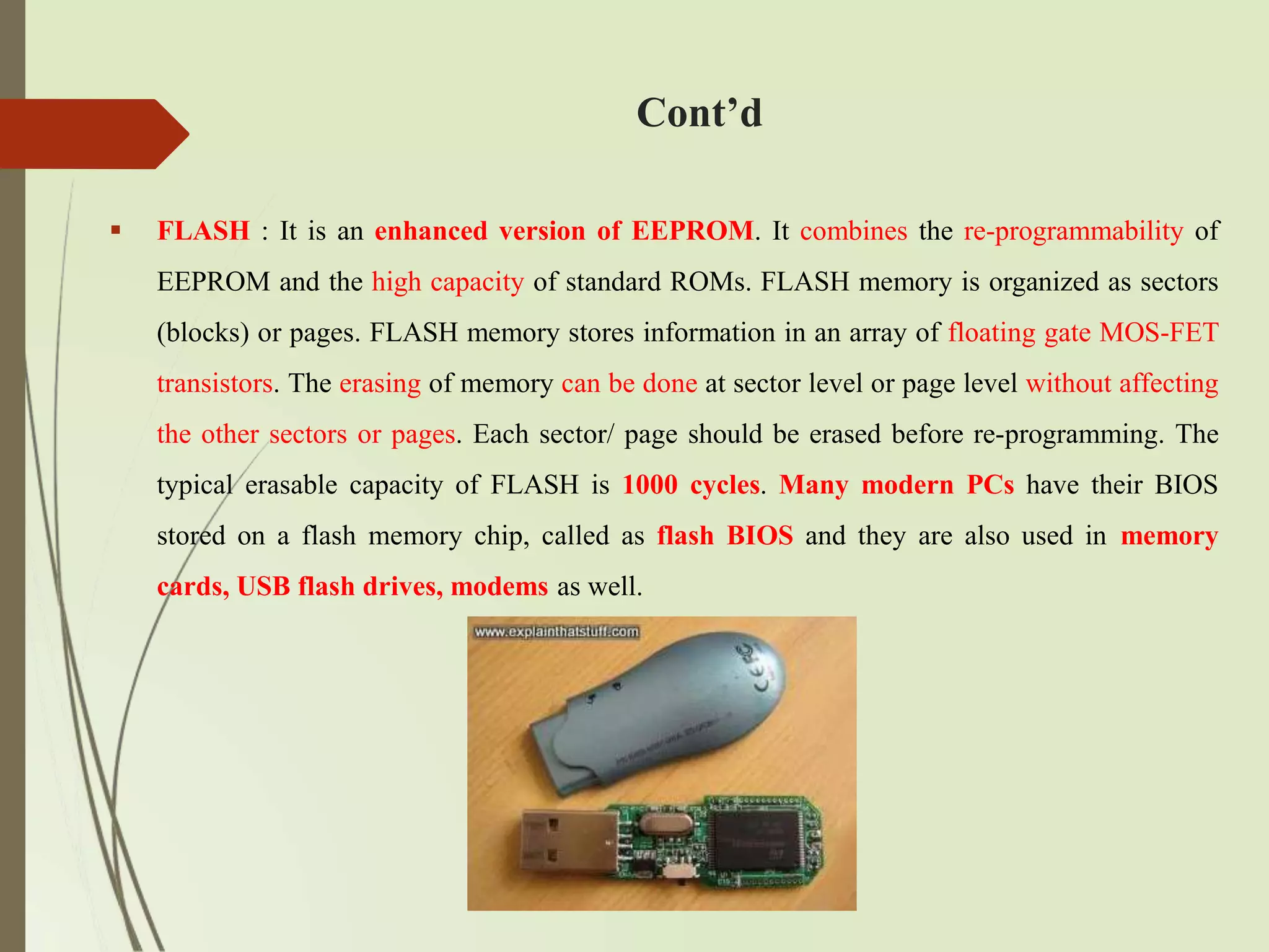
FLASH :It is an enhanced version of EEPROM. It combines the re-programmability of
EEPROM and the high capacity of standard ROMs. FLASH memory is organized as sectors
(blocks) or pages. FLASH memory stores information in an array of floating gate MOS-FET
transistors. The erasing of memory can be done at sector level or page level without affecting
the other sectors or pages. Each sector/ page should be erased before re-programming. The
typical erasable capacity of FLASH is 1000 cycles. Many modern PCs have their BIOS
stored on a flash memory chip, called as flash BIOS and they are also used in memory
cards, USB flash drives, modems as well.
Cont’d
60.
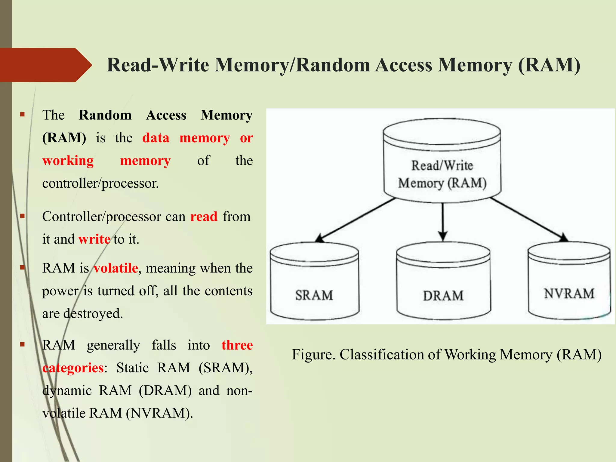
The RandomAccess Memory
(RAM) is the data memory or
working memory of the
controller/processor.
Controller/processor can read from
it and write to it.
RAM is volatile, meaning when the
power is turned off, all the contents
are destroyed.
RAM generally falls into three
categories: Static RAM (SRAM),
dynamic RAM (DRAM) and non-
volatile RAM (NVRAM).
Read-Write Memory/Random Access Memory (RAM)
Figure. Classification of Working Memory (RAM)
61.
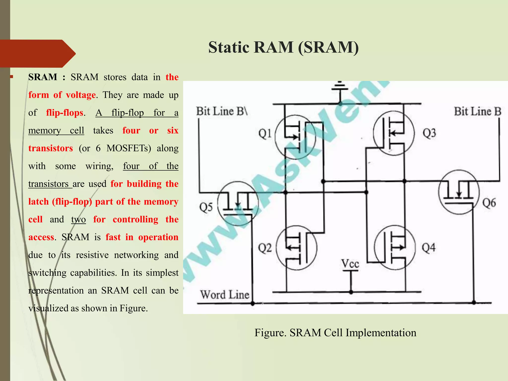
Static RAM (SRAM)
SRAM : SRAM stores data in the
form of voltage. They are made up
of flip-flops. A flip-flop for a
memory cell takes four or six
transistors (or 6 MOSFETs) along
with some wiring, four of the
transistors are used for building the
latch (flip-flop) part of the memory
cell and two for controlling the
access. SRAM is fast in operation
due to its resistive networking and
switching capabilities. In its simplest
representation an SRAM cell can be
visualized as shown in Figure.
Figure. SRAM Cell Implementation
62.
Cont’d
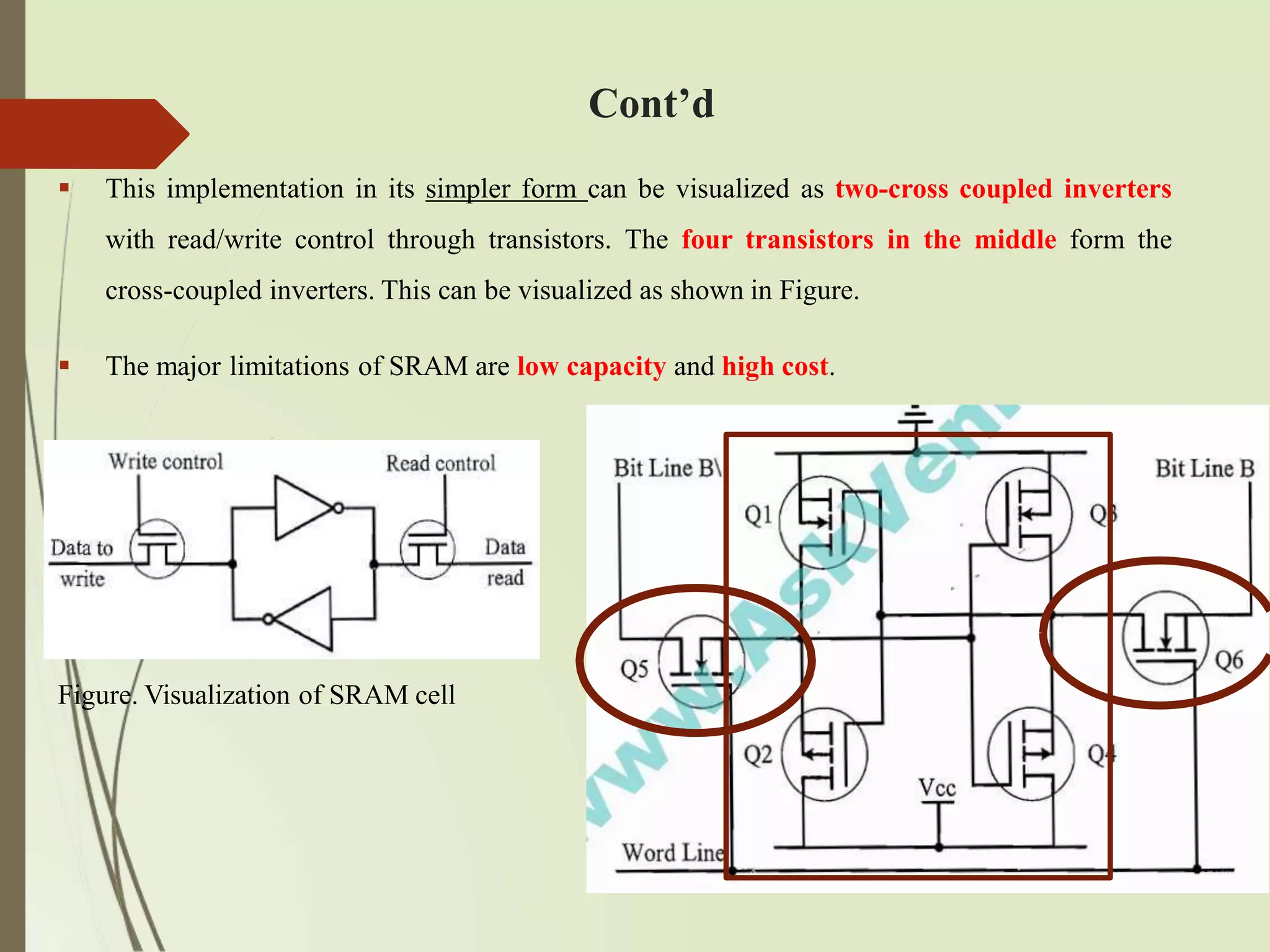
This implementationin its simpler form can be visualized as two-cross coupled inverters
with read/write control through transistors. The four transistors in the middle form the
cross-coupled inverters. This can be visualized as shown in Figure.
The major limitations of SRAM are low capacity and high cost.
Figure. Visualization of SRAM cell
63.
Dynamic RAM (DRAM)
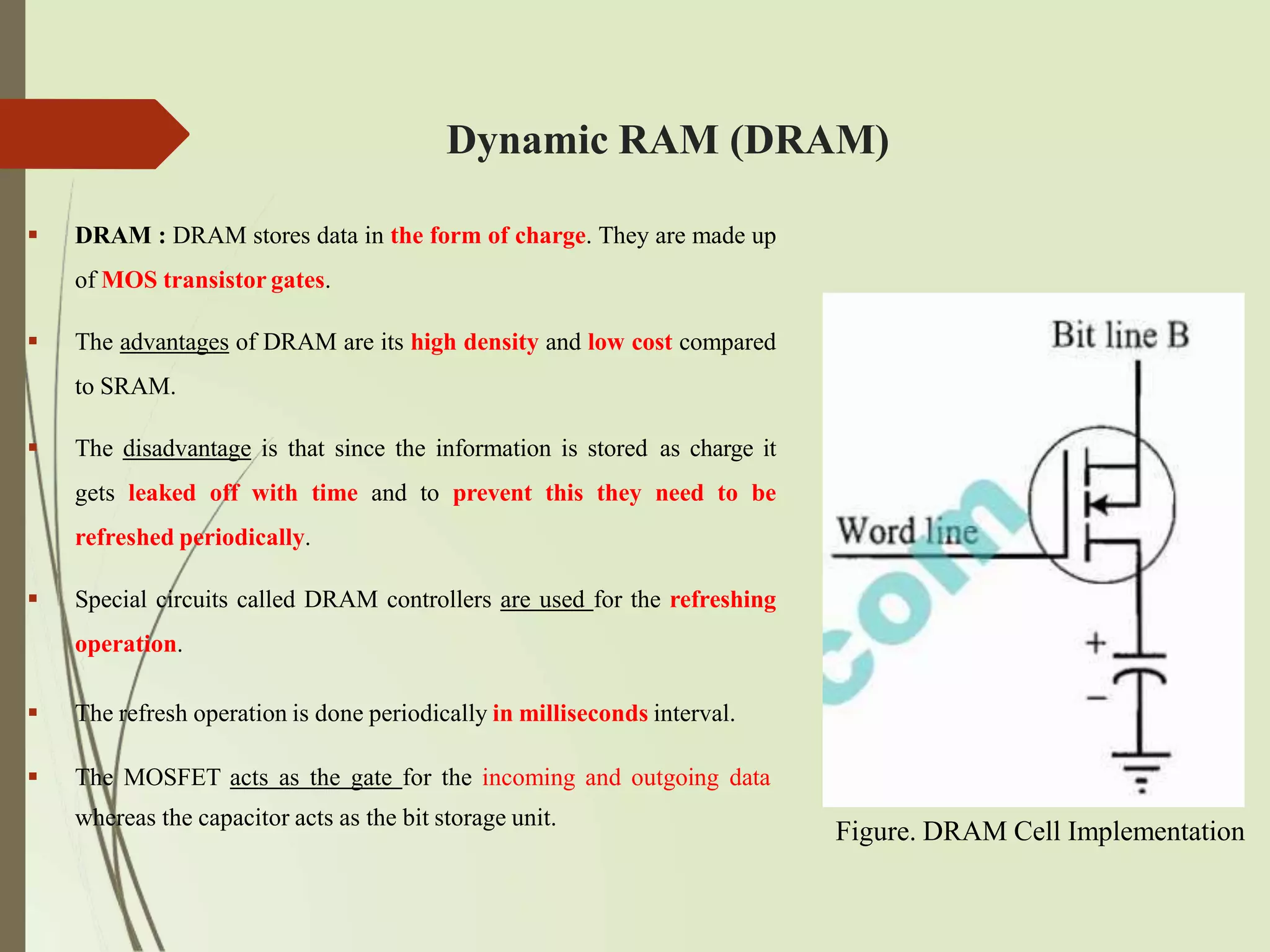
DRAM : DRAM stores data in the form of charge. They are made up
of MOS transistor gates.
The advantages of DRAM are its high density and low cost compared
to SRAM.
The disadvantage is that since the information is stored as charge it
gets leaked off with time and to prevent this they need to be
refreshed periodically.
Special circuits called DRAM controllers are used for the refreshing
operation.
The refresh operation is done periodically in milliseconds interval.
The MOSFET acts as the gate for the incoming and outgoing data
whereas the capacitor acts as the bit storage unit.
Figure. DRAM Cell Implementation
64.
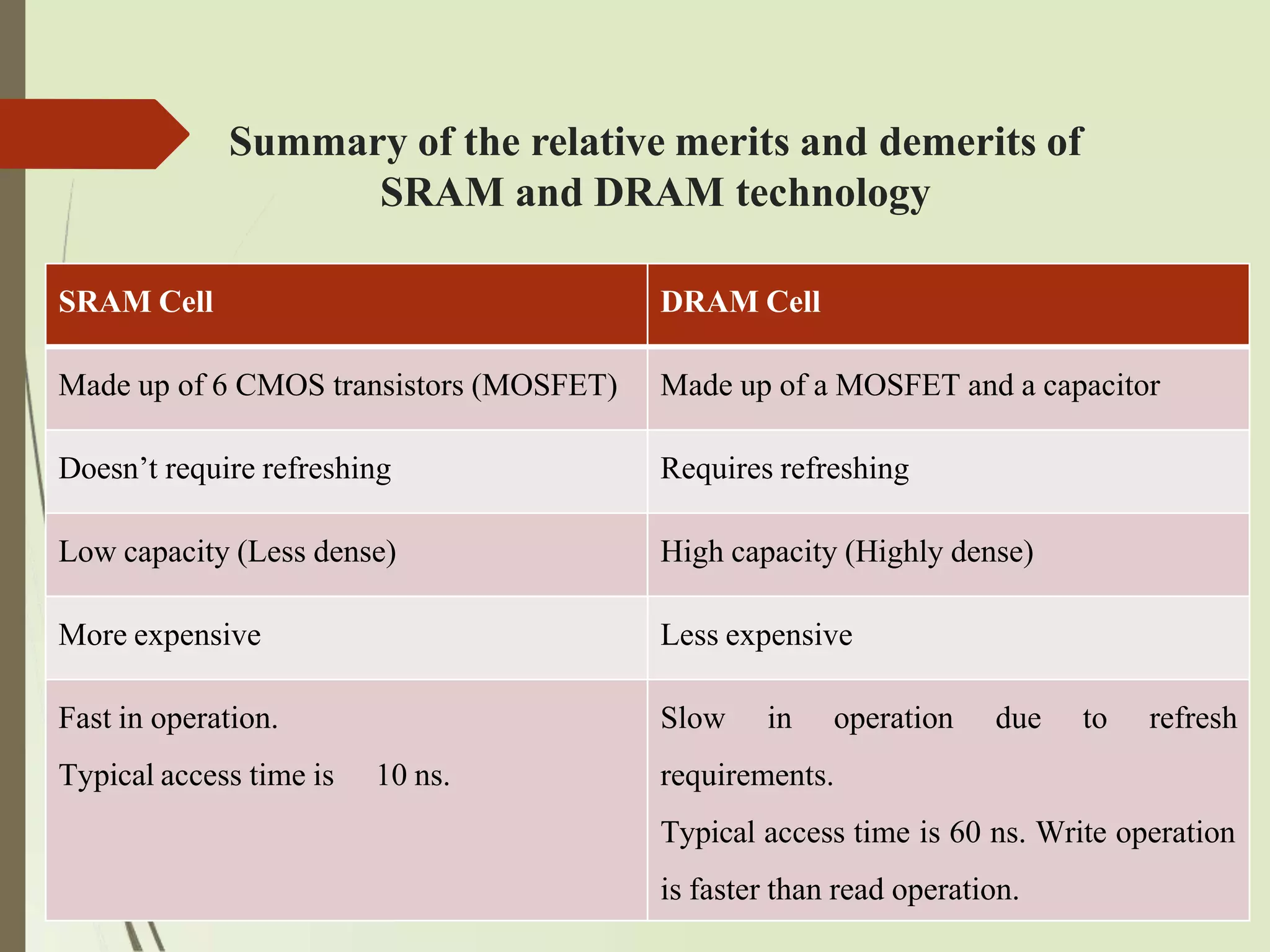
Summary of therelative merits and demerits of
SRAM and DRAM technology
SRAM Cell DRAM Cell
Made up of 6 CMOS transistors (MOSFET) Made up of a MOSFET and a capacitor
Doesn’t require refreshing Requires refreshing
Low capacity (Less dense) High capacity (Highly dense)
More expensive Less expensive
Fast in operation. Slow in operation due to refresh
Typical access time is 10 ns. requirements.
Typical access time is 60 ns. Write operation
is faster than read operation.
65.
NVRAM
NVRAM: Non-volatileRAM is a random access memory with battery backup.
It contains static RAM based memory and a minute battery for providing supply to the
memory in the absence of external power supply.
The memory and battery are packed together in a single package.
NVRAM is used for the non-volatile storage of results of operations.
The life span of NVRAM is expected to be around 10 years.
DS1744 from Maxim/Dallas is an example for 32 KB NVRAM.
66.
2.3 Sensors andActuators
A sensor is a transducer device that converts energy from one form to another
for any measurement or control purpose.
The changes in system environment or variables are detected by the sensors
connected to the input port of the embedded system.
Actuator is a form of transducer device (mechanical or electrical) which
converts signals to corresponding physical action (motion). Actuator acts as an
output device.
If the embedded system is designed for any controlling purpose, the system will
produce some changes in the controlling variable to bring the controlled variable to
the desired value.
It is achieved through an actuator connected to the output port of the embedded
system.
67.
Cont’d
If theembedded system is designed for monitoring purpose only, then
there is no need for including an actuator in the system.
For example, take the case of an ECG machine. It is designed to monitor
the heart beat status of a patient and it cannot impose a control over the
patient’s heart beat and its order. The sensors used here are the different
electrode sets connected to the body of the patient. The variations are
captured and presented to the user (may be a doctor) through a visual
display or some printed chart.
68.
I/O Subsystem
TheI/O subsystem of the embedded system facilitates the interaction of the
embedded system with the external world.
The interaction happens through the sensors and actuators connected to the input
and output ports respectively of the embedded system.
The sensors may not be directly interfaced to the input ports, instead they may be
interfaced through signal conditioning and translating systems like ADC,
optocouplers, etc.
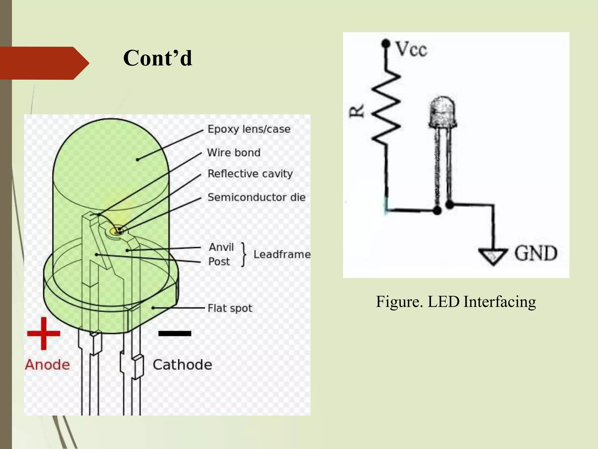
Light Emitting Diode(LED)
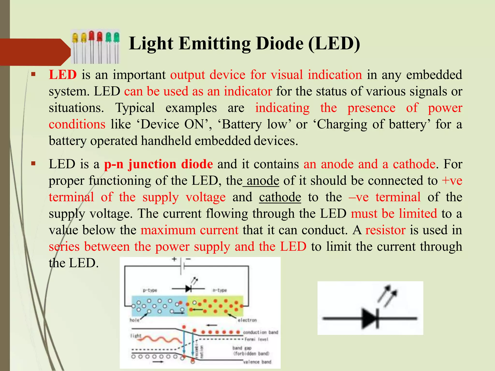
LED is an important output device for visual indication in any embedded
system. LED can be used as an indicator for the status of various signals or
situations. Typical examples are indicating the presence of power
conditions like ‘Device ON’, ‘Battery low’ or ‘Charging of battery’ for a
battery operated handheld embedded devices.
LED is a p-n junction diode and it contains an anode and a cathode. For
proper functioning of the LED, the anode of it should be connected to +ve
terminal of the supply voltage and cathode to the –ve terminal of the
supply voltage. The current flowing through the LED must be limited to a
value below the maximum current that it can conduct. A resistor is used in
series between the power supply and the LED to limit the current through
the LED.
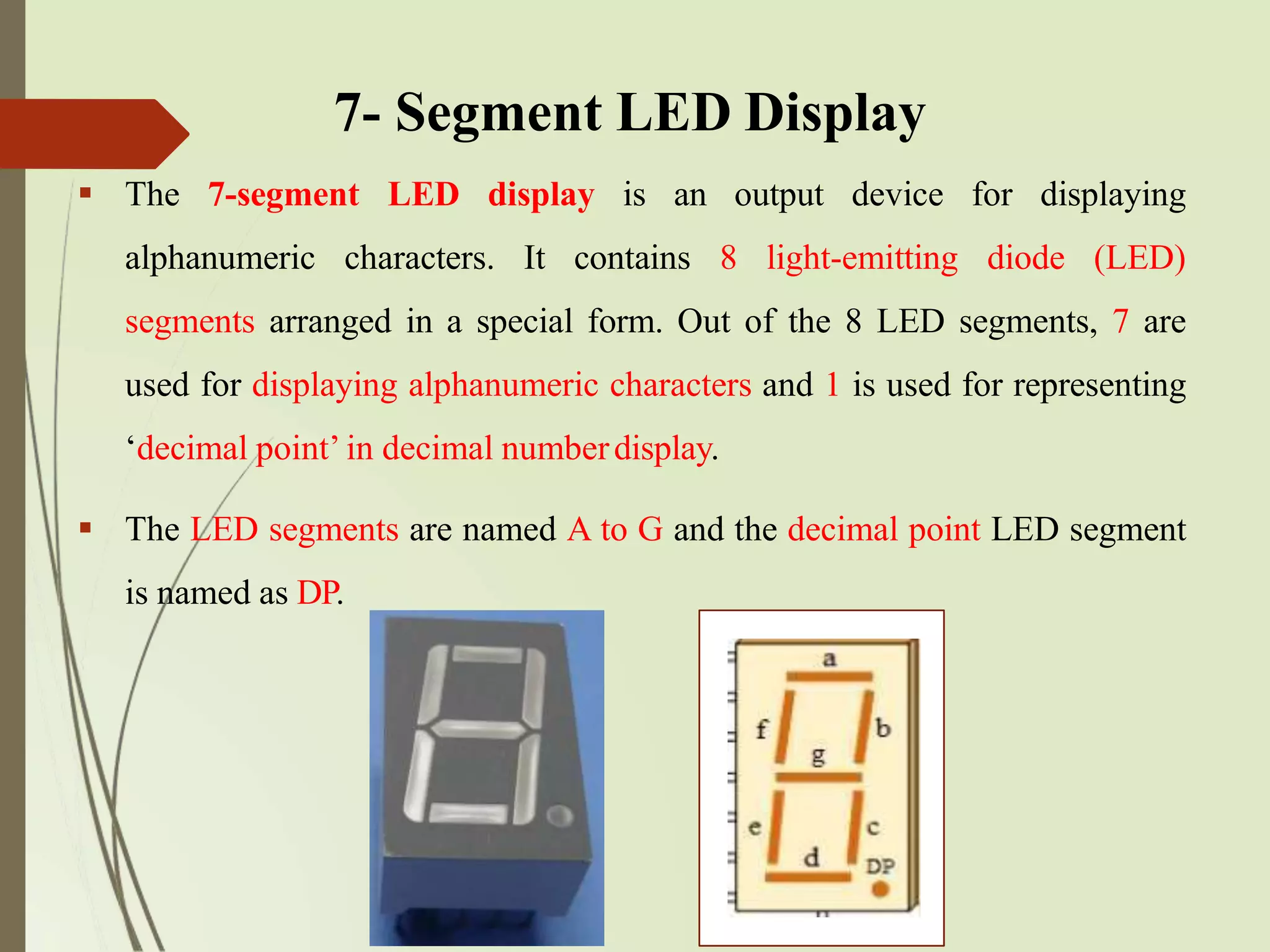
The 7-segmentLED display is an output device for displaying
alphanumeric characters. It contains 8 light-emitting diode (LED)
segments arranged in a special form. Out of the 8 LED segments, 7 are
used for displaying alphanumeric characters and 1 is used for representing
‘decimal point’ in decimal numberdisplay.
The LED segments are named A to G and the decimal point LED segment
is named as DP.
7- Segment LED Display
73.
Cont’d
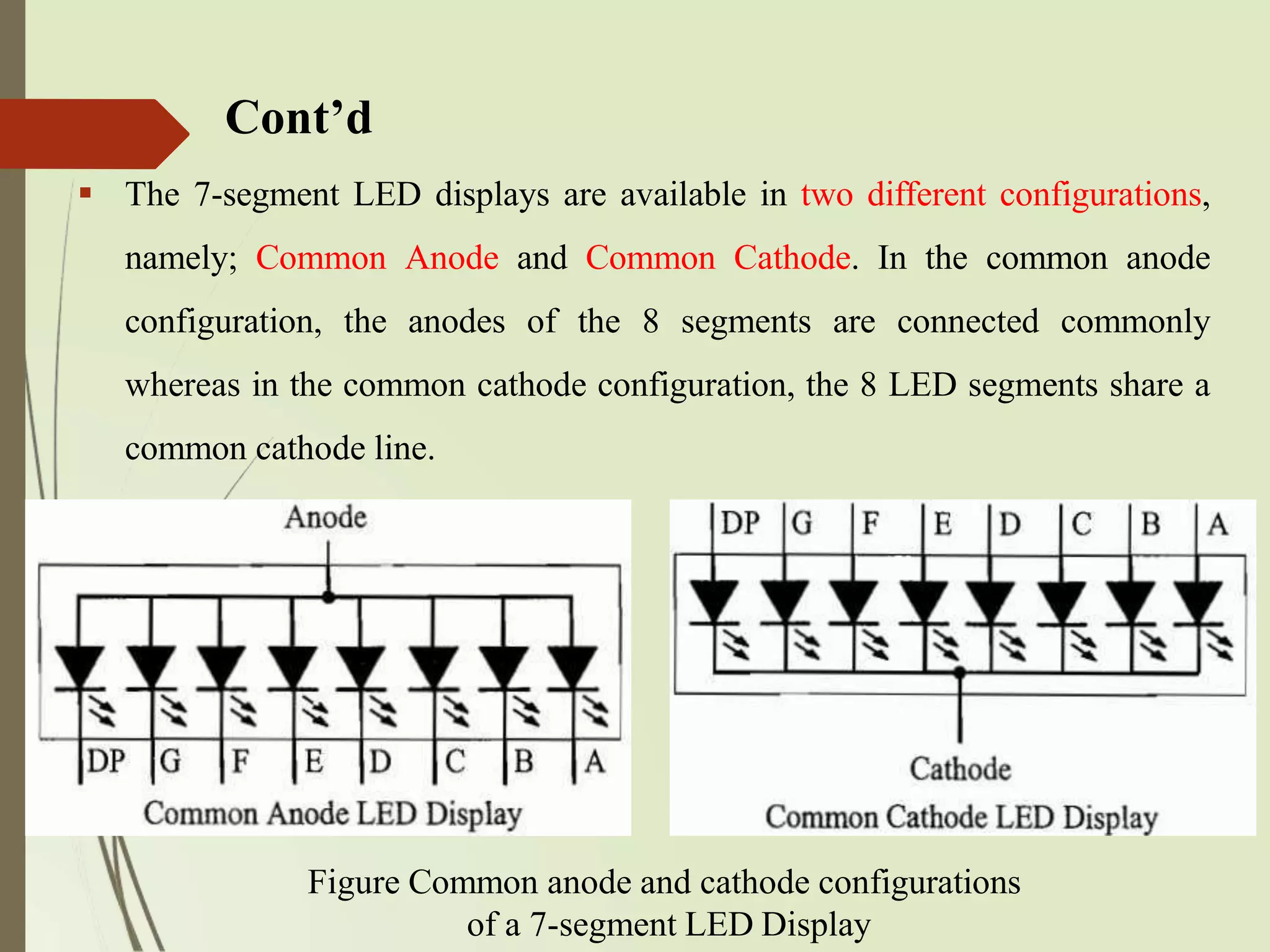
Figure Common anodeand cathode configurations
of a 7-segment LED Display
The 7-segment LED displays are available in two different configurations,
namely; Common Anode and Common Cathode. In the common anode
configuration, the anodes of the 8 segments are connected commonly
whereas in the common cathode configuration, the 8 LED segments share a
common cathode line.
74.
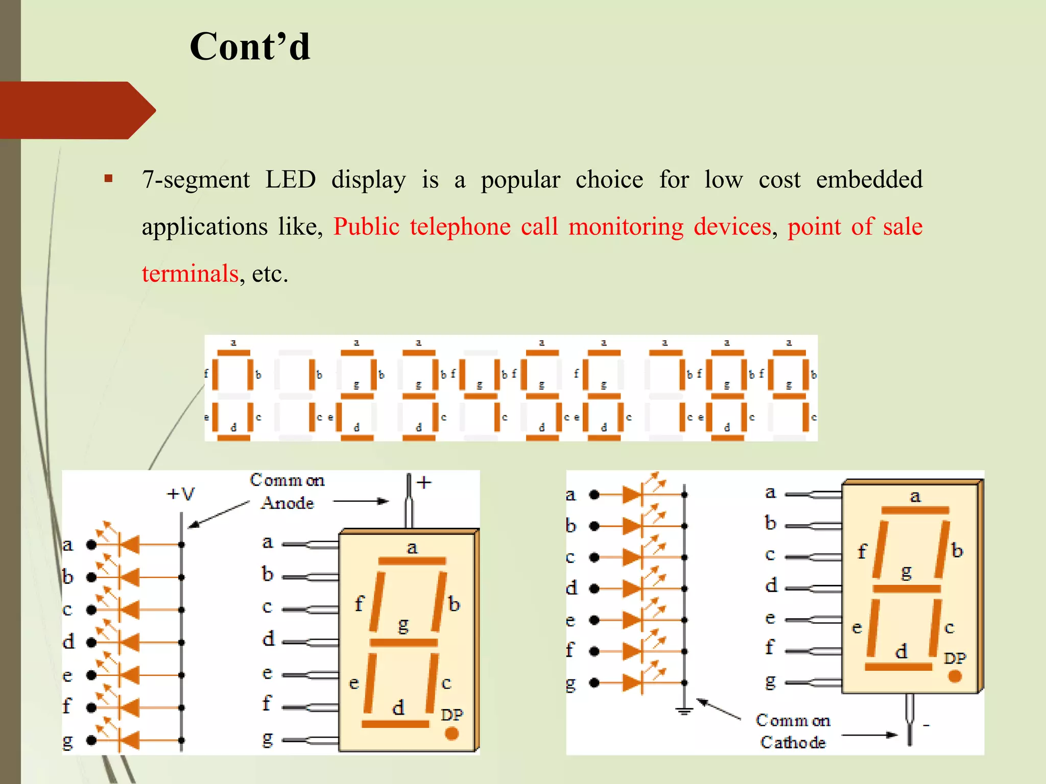
Cont’d
7-segment LEDdisplay is a popular choice for low cost embedded
applications like, Public telephone call monitoring devices, point of sale
terminals, etc.
75.
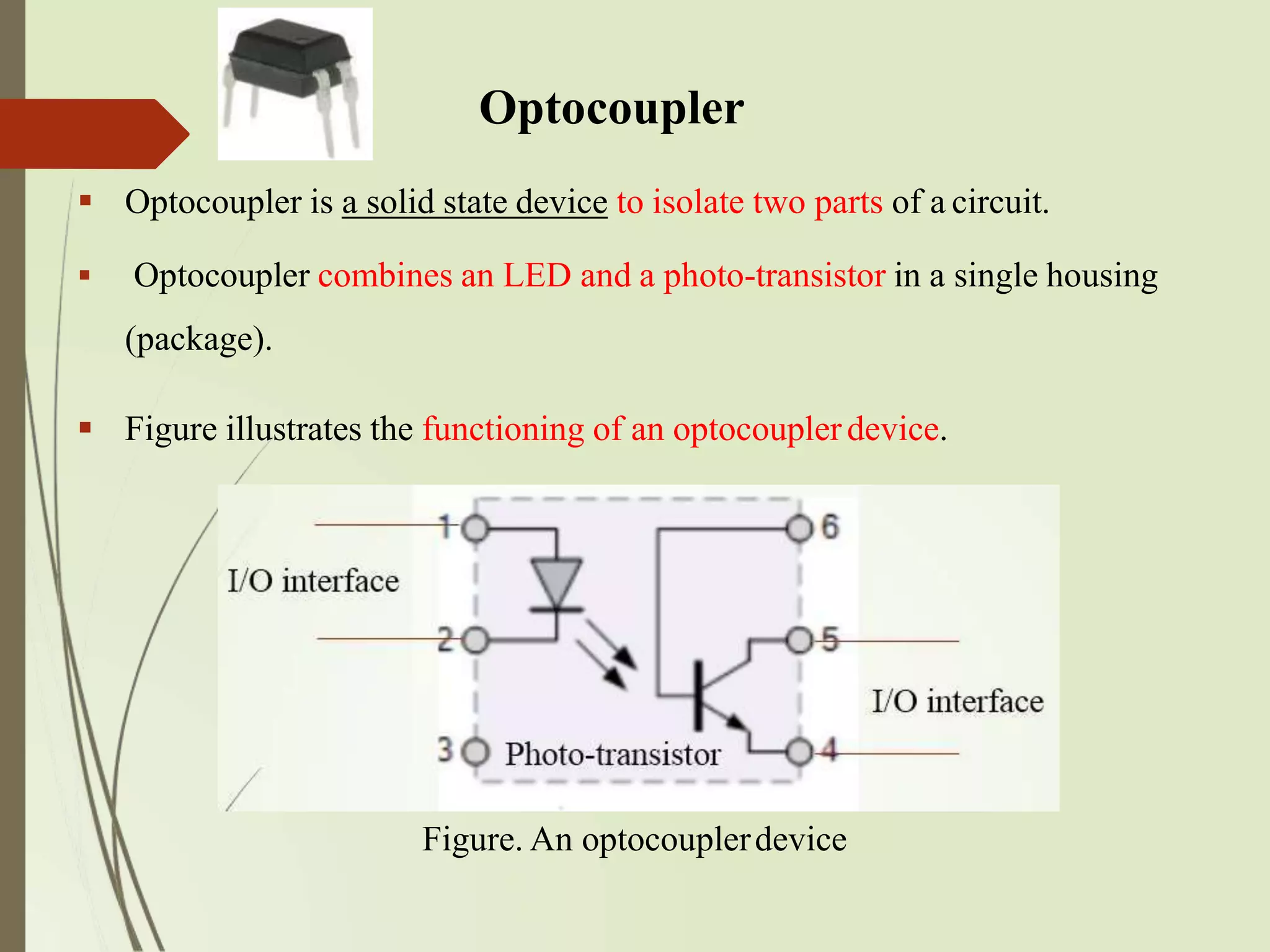
Optocoupler
Optocoupler isa solid state device to isolate two parts of a circuit.
Optocoupler combines an LED and a photo-transistor in a single housing
(package).
Figure illustrates the functioning of an optocouplerdevice.
Figure. An optocouplerdevice
76.
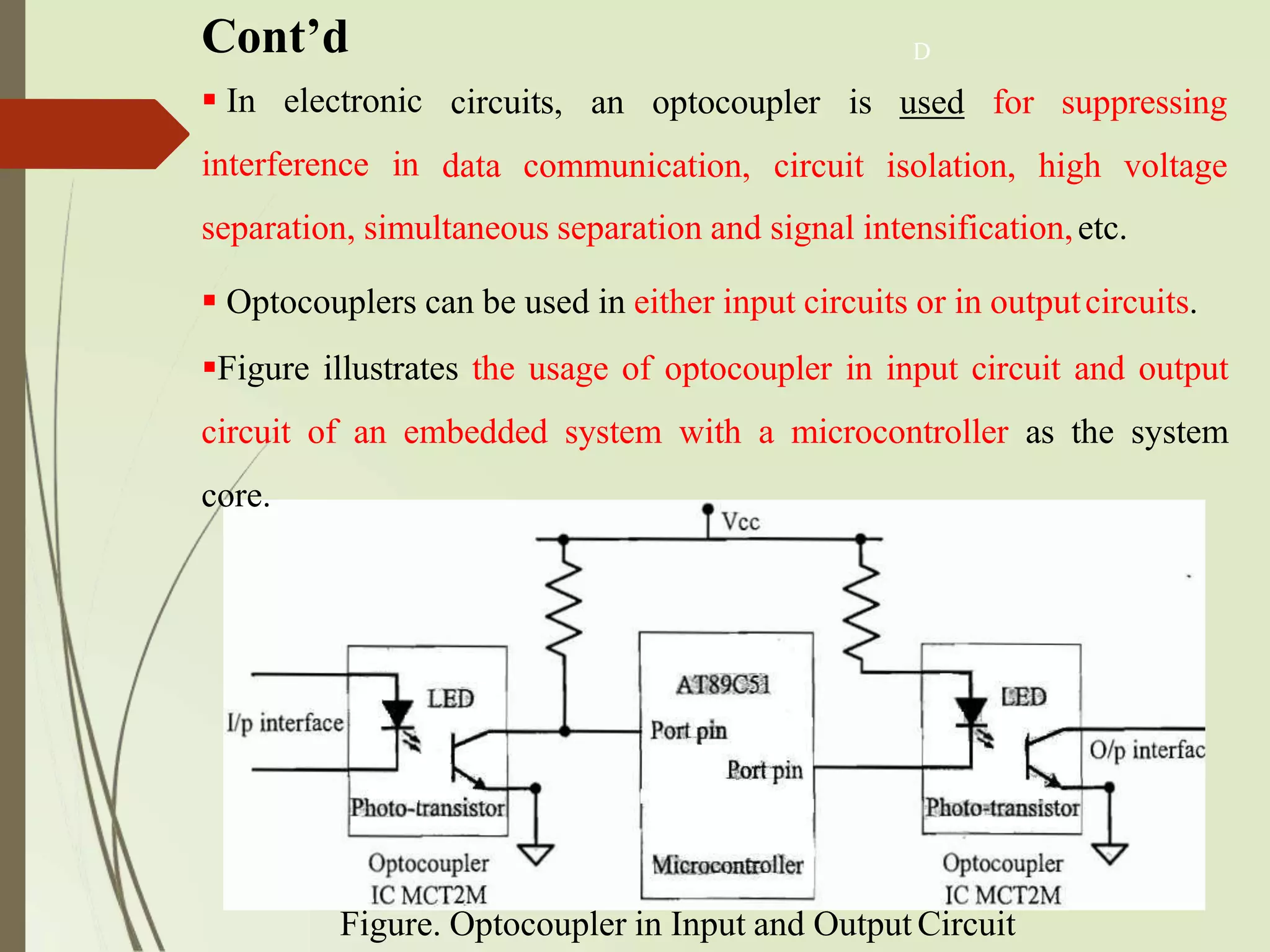
Cont’d
Figure. Optocoupler inInput and Output Circuit
In electronic
interference in
separation, simultaneous separation and signal intensification,etc.
Optocouplers can be used in either input circuits or in outputcircuits.
Figure illustrates the usage of optocoupler in input circuit and output
circuit of an embedded system with a microcontroller as the system
core.
D
circuits, an optocoupler is used for suppressing
data communication, circuit isolation, high voltage
77.
Stepper Motor
Astepper motor is an electro-mechanical device which generates discrete
displacement (motion) in response to dc electrical signals.
It differs from the normal dc motor in itsoperation.
The dc motor produces continuous rotation on applying dc voltage
whereas a stepper motor produces discrete rotation in response to the dc
voltage applied to it.
Stepper motors are widely used in industrial embedded applications,
consumer electronic products and robotics controlsystems.
The paper feed mechanism of a printer/fax makes use of stepper motors for
its functioning.
78.
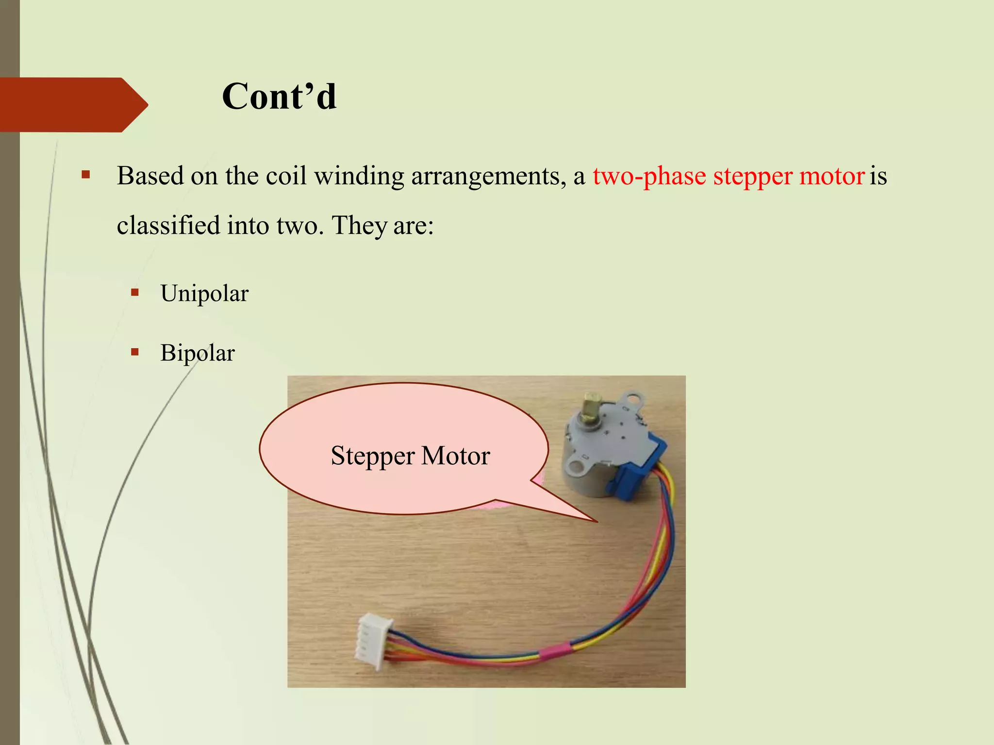
Cont’d
Based onthe coil winding arrangements, a two-phase stepper motoris
classified into two. They are:
Unipolar
Bipolar
Stepper Motor
79.
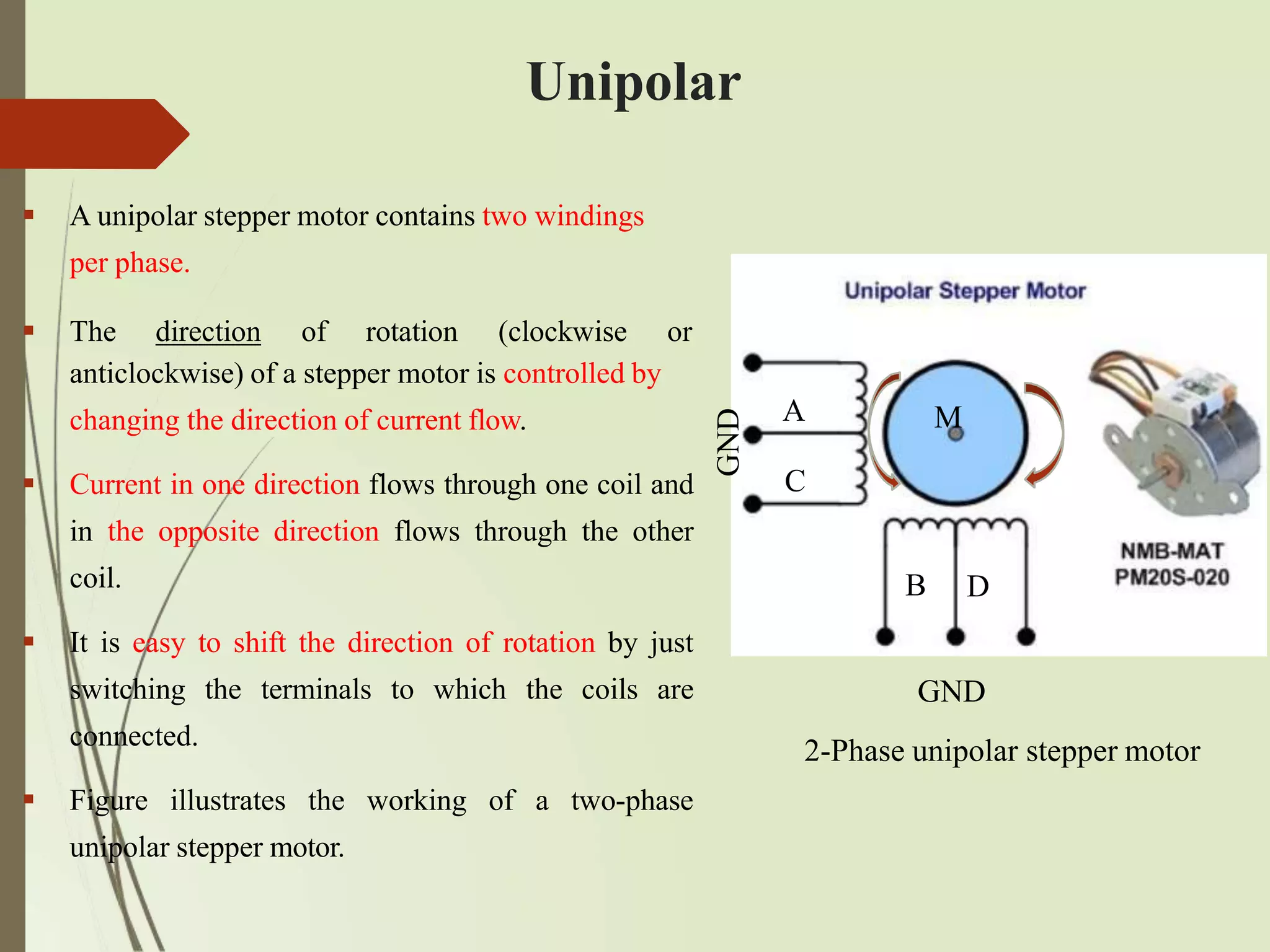
Unipolar
anticlockwise) of astepper motor is controlled by
changing the direction of current flow.
Current in one direction flows through one coil and
in the opposite direction flows through the other
coil.
It is easy to shift the direction of rotation by just
switching the terminals to which the coils are
connected.
Figure illustrates the working of a two-phase
unipolar stepper motor.
A unipolar stepper motor contains two windings
per phase.
The direction of rotation (clockwise or
A
C
M
GND
B D
GND
2-Phase unipolar stepper motor
80.
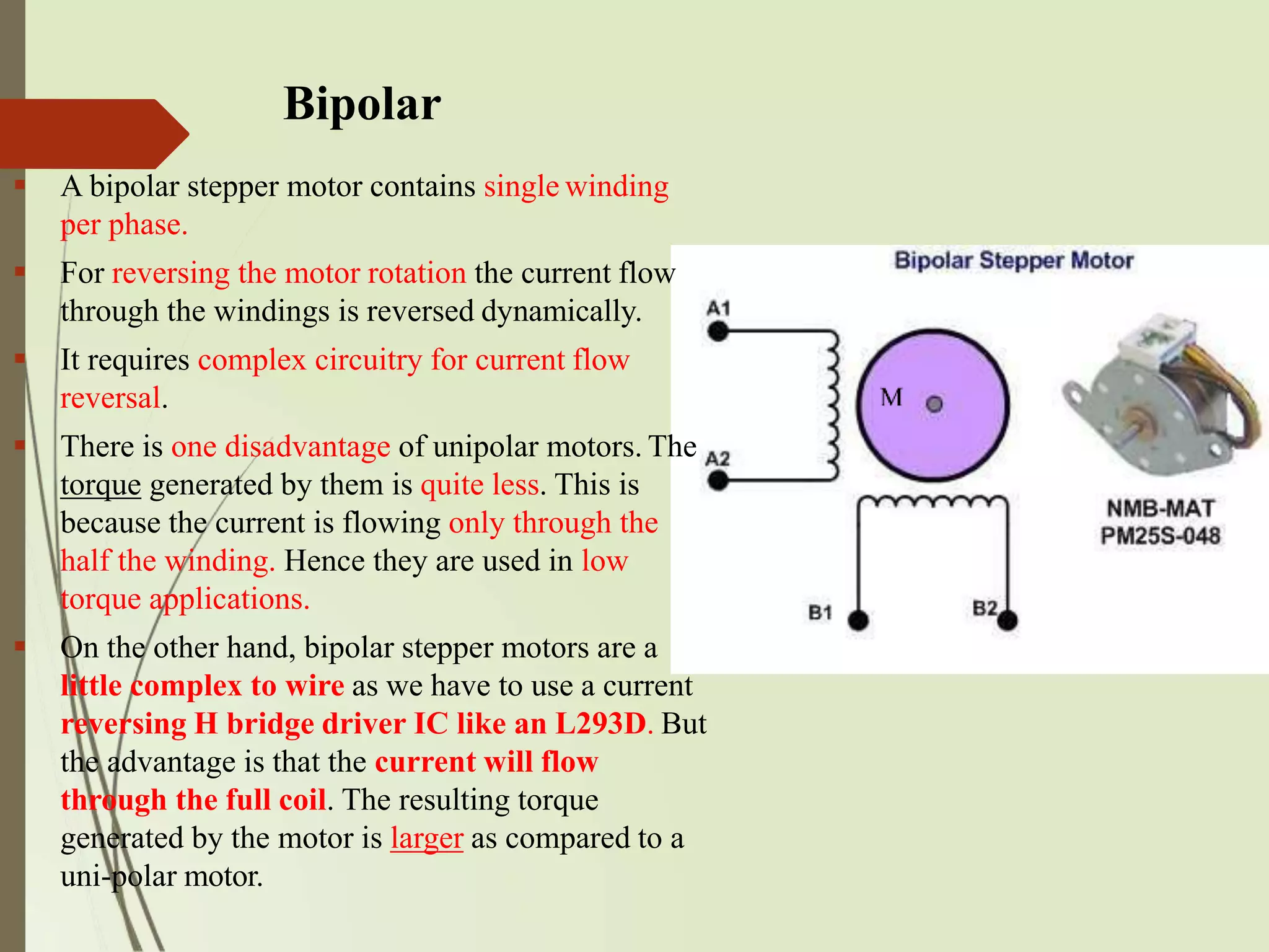
Bipolar
A bipolarstepper motor contains single winding
per phase.
For reversing the motor rotation the current flow
through the windings is reversed dynamically.
It requires complex circuitry for current flow
reversal.
There is one disadvantage of unipolar motors. The
torque generated by them is quite less. This is
because the current is flowing only through the
half the winding. Hence they are used in low
torque applications.
On the other hand, bipolar stepper motors are a
little complex to wire as we have to use a current
reversing H bridge driver IC like an L293D. But
the advantage is that the current will flow
through the full coil. The resulting torque
generated by the motor is larger as compared to a
uni-polar motor.
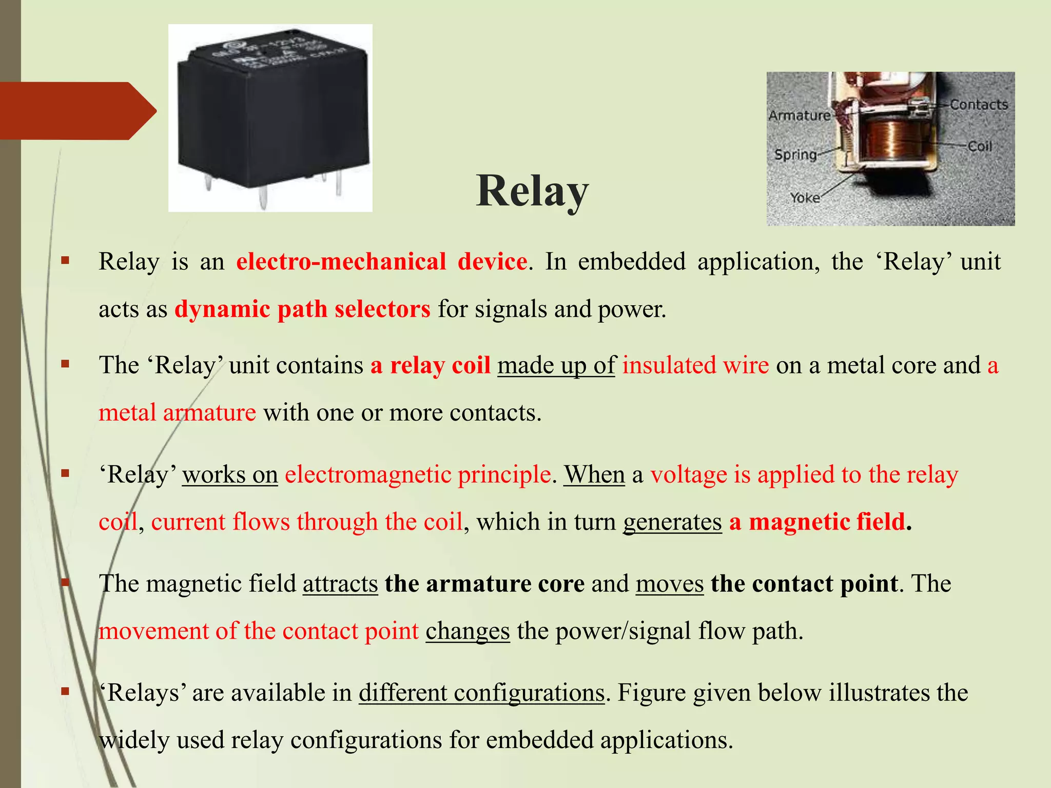
Relay
Relay isan electro-mechanical device. In embedded application, the ‘Relay’ unit
acts as dynamic path selectors for signals and power.
The ‘Relay’ unit contains a relay coil made up of insulated wire on a metal core and a
metal armature with one or more contacts.
‘Relay’ works on electromagnetic principle. When a voltage is applied to the relay
coil, current flows through the coil, which in turn generates a magnetic field.
The magnetic field attracts the armature core and moves the contact point. The
movement of the contact point changes the power/signal flow path.
‘Relays’ are available in different configurations. Figure given below illustrates the
widely used relay configurations for embedded applications.
83.
Cont’d
Figure Relay Configurations
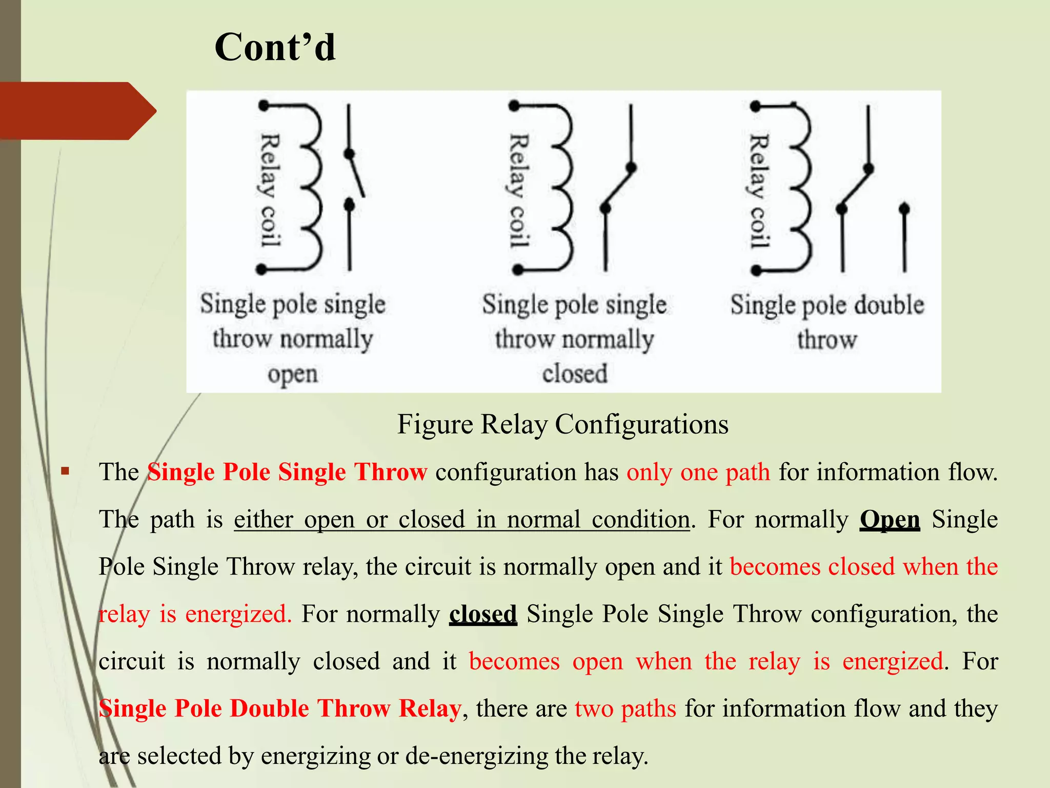
The Single Pole Single Throw configuration has only one path for information flow.
The path is either open or closed in normal condition. For normally Open Single
Pole Single Throw relay, the circuit is normally open and it becomes closed when the
relay is energized. For normally closed Single Pole Single Throw configuration, the
circuit is normally closed and it becomes open when the relay is energized. For
Single Pole Double Throw Relay, there are two paths for information flow and they
are selected by energizing or de-energizing the relay.
84.
Piezo Buzzer
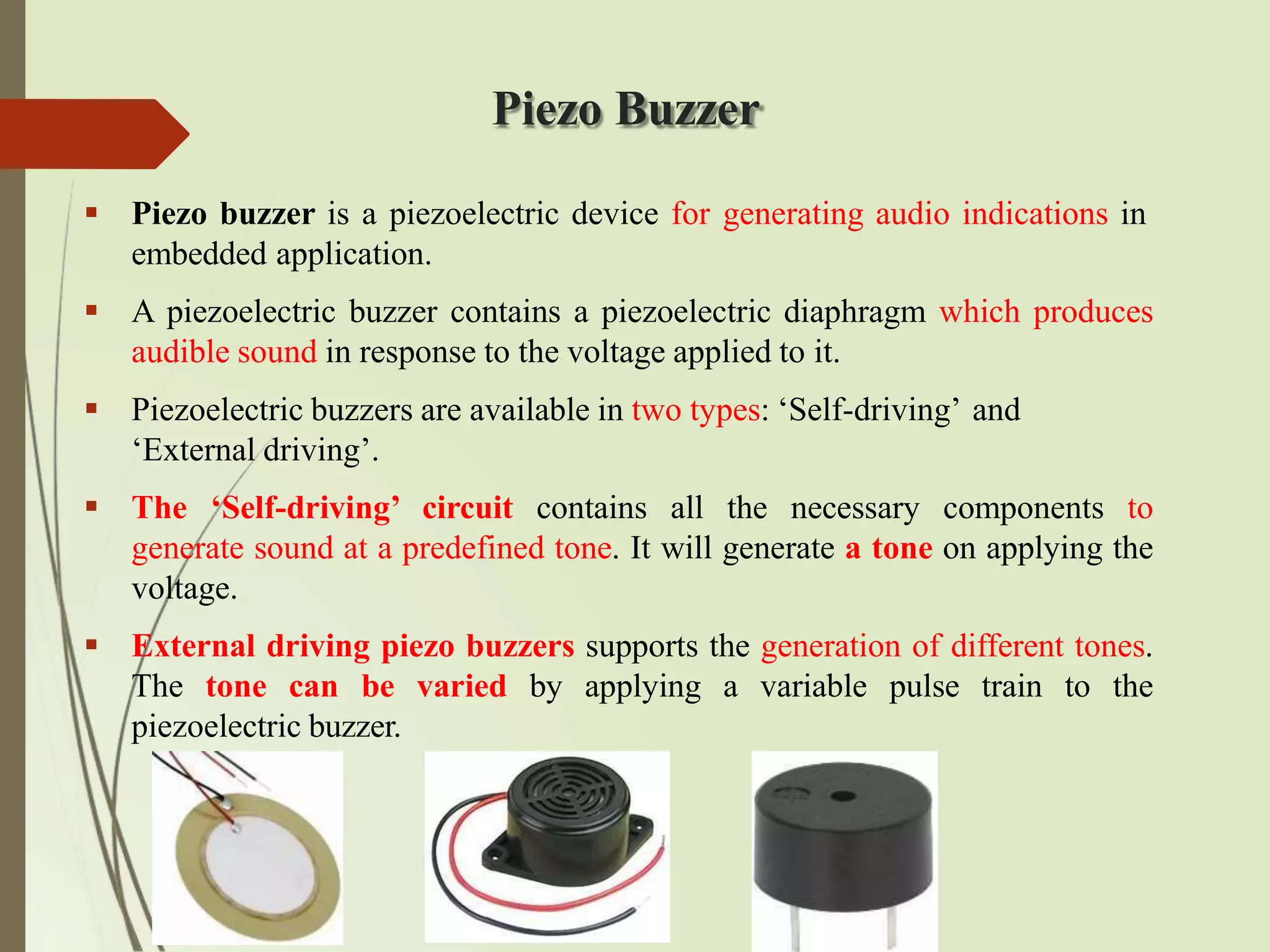
Piezobuzzer is a piezoelectric device for generating audio indications in
embedded application.
A piezoelectric buzzer contains a piezoelectric diaphragm which produces
audible sound in response to the voltage applied to it.
Piezoelectric buzzers are available in two types: ‘Self-driving’ and
‘External driving’.
The ‘Self-driving’ circuit contains all the necessary components to
generate sound at a predefined tone. It will generate a tone on applying the
voltage.
External driving piezo buzzers supports the generation of different tones.
The tone can be varied by applying a variable pulse train to the
piezoelectric buzzer.
85.
Push Button Switch
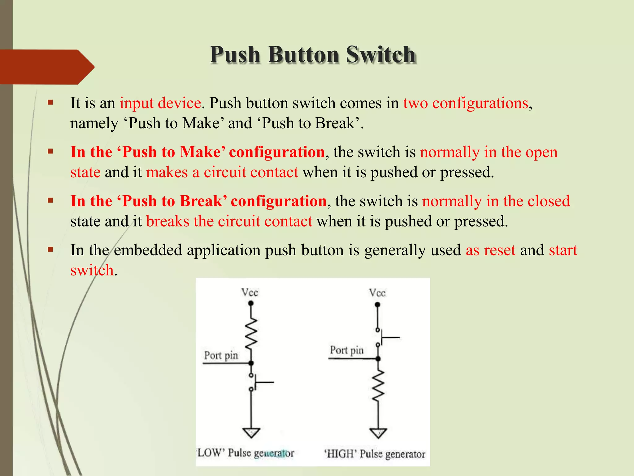
It is an input device. Push button switch comes in two configurations,
namely ‘Push to Make’ and ‘Push to Break’.
In the ‘Push to Make’ configuration, the switch is normally in the open
state and it makes a circuit contact when it is pushed or pressed.
In the ‘Push to Break’ configuration, the switch is normally in the closed
state and it breaks the circuit contact when it is pushed or pressed.
In the embedded application push button is generally used as reset and start
switch.
86.
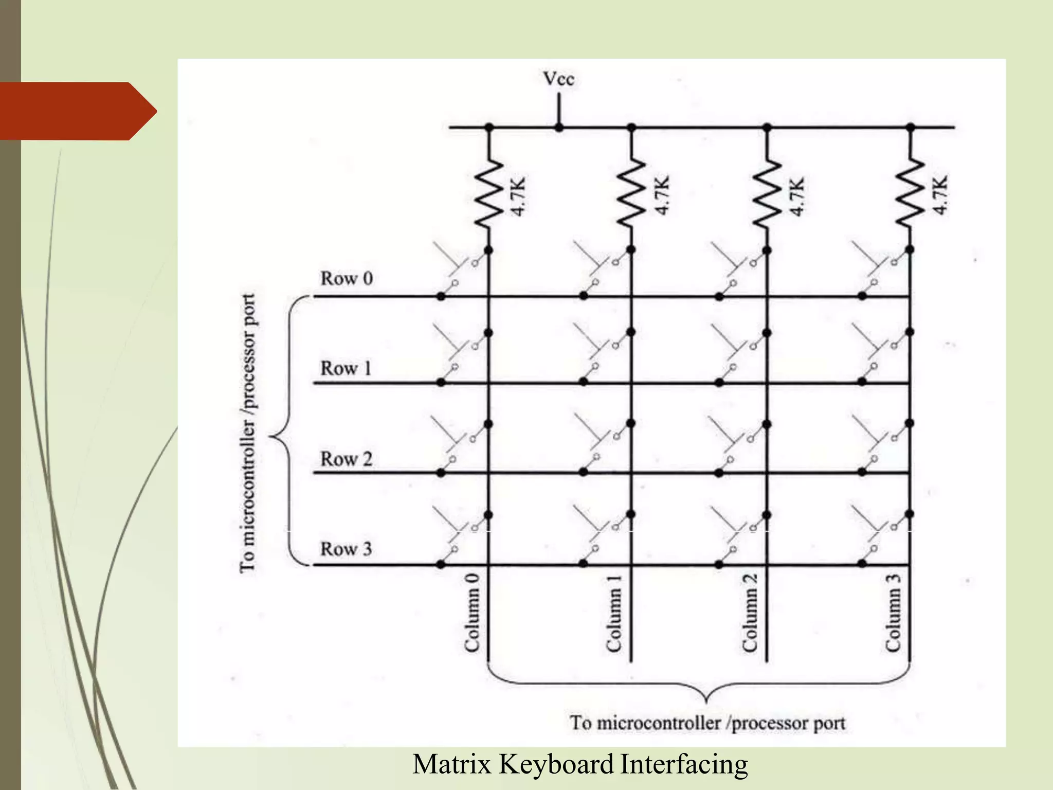
Keyboard
Keyboard isan input device for user interfacing. If the number of keys
required is very limited, push button switches can be used and they can be
directly interfaced to the port pins for reading.
Matrix keyboard is an optimum solution for handling large key
requirements. It greatly reduces the number of interface connections.
For example, for interfacing 16 keys, in the direct interfacing technique 16 port
pins are required, whereas the matrix keyboard only 8 lines are required. The
16 keys are arranged in a 4 column*4 row matrix.
2.4 Communication Interface
For an embedded product, the communication interface can be viewed in two
different perspectives; namely; Device/board level communication interface
(Onboard Communication Interface) and Product level communication
interface (External Communication Interface).
Embedded product is a combination of different types of components
(chips/devices) arranged on a printed circuit board (PCB). Serial interfaces
like I2C, SPI, UART, 1-Wire, etc and parallel bus interface are examples of
‘Onboard Communication Interface’.
89.
Onboard Communication Interfaces
Onboard Communication Interface refers to the different
communication channels/buses for interconnecting the various
integrated circuits and other peripherals within the embedded system.
The various interfaces for onboard communication are as follows:
i. Inter Integrated Circuit (I2C) Bus
ii. Serial Peripheral Interface (SPI) Bus
iii. Universal Asynchronous Receiver Transmitter(UART)
iv. 1-Wire Interface
v. Parallel Interface
90.
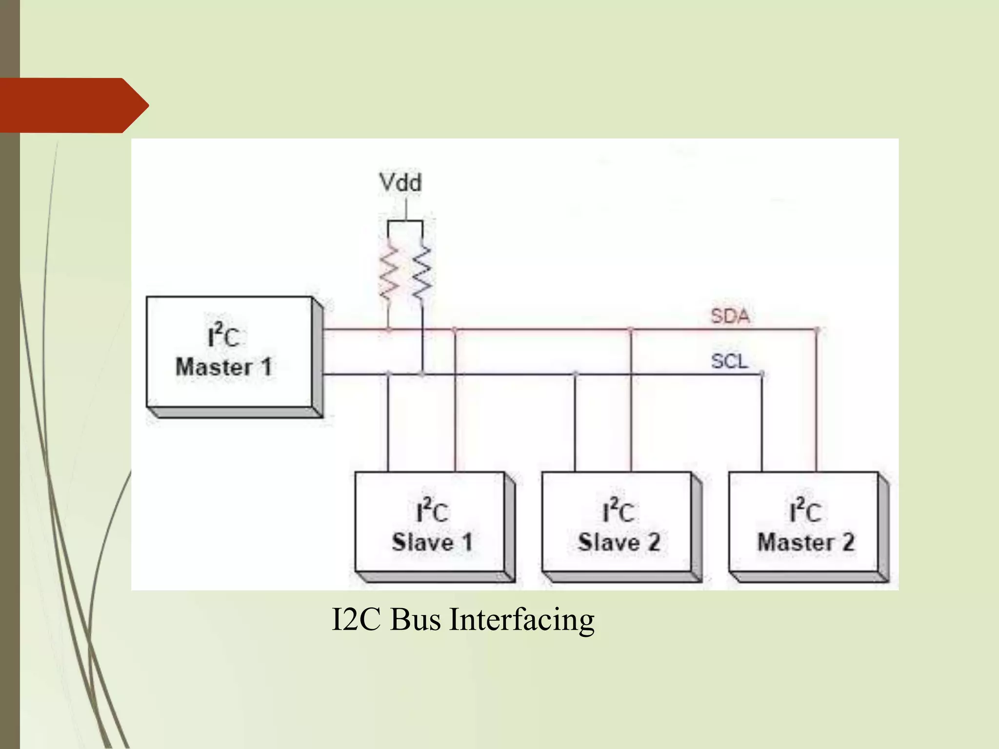
Inter Integrated Circuit(I2C) Bus
The Inter Integrated Circuit Bus is a synchronous bi-directional half duplex
two wire serial interface bus. The I2C bus comprise of two bus lines, namely;
Serial Clock-SCL and Serial Data-SDA.
SCL line is responsible for generating synchronization clock pulses and
SDA is responsible for transmitting the serial data across devices.
Devices connected to the I2C bus can act as either ‘Master’ device or ‘Slave’
device.
The ‘Master’ device is responsible for controlling the communication by
initiating/terminating data transfer, sending data and generating necessary
synchronization clock pulses.
‘Slave’ devices wait for the commands from the master and respond upon
receiving the commands. ‘Master’ and ‘Slave’ devices can act as either
transmitter or receiver. I2C supports multi masters on the same bus.
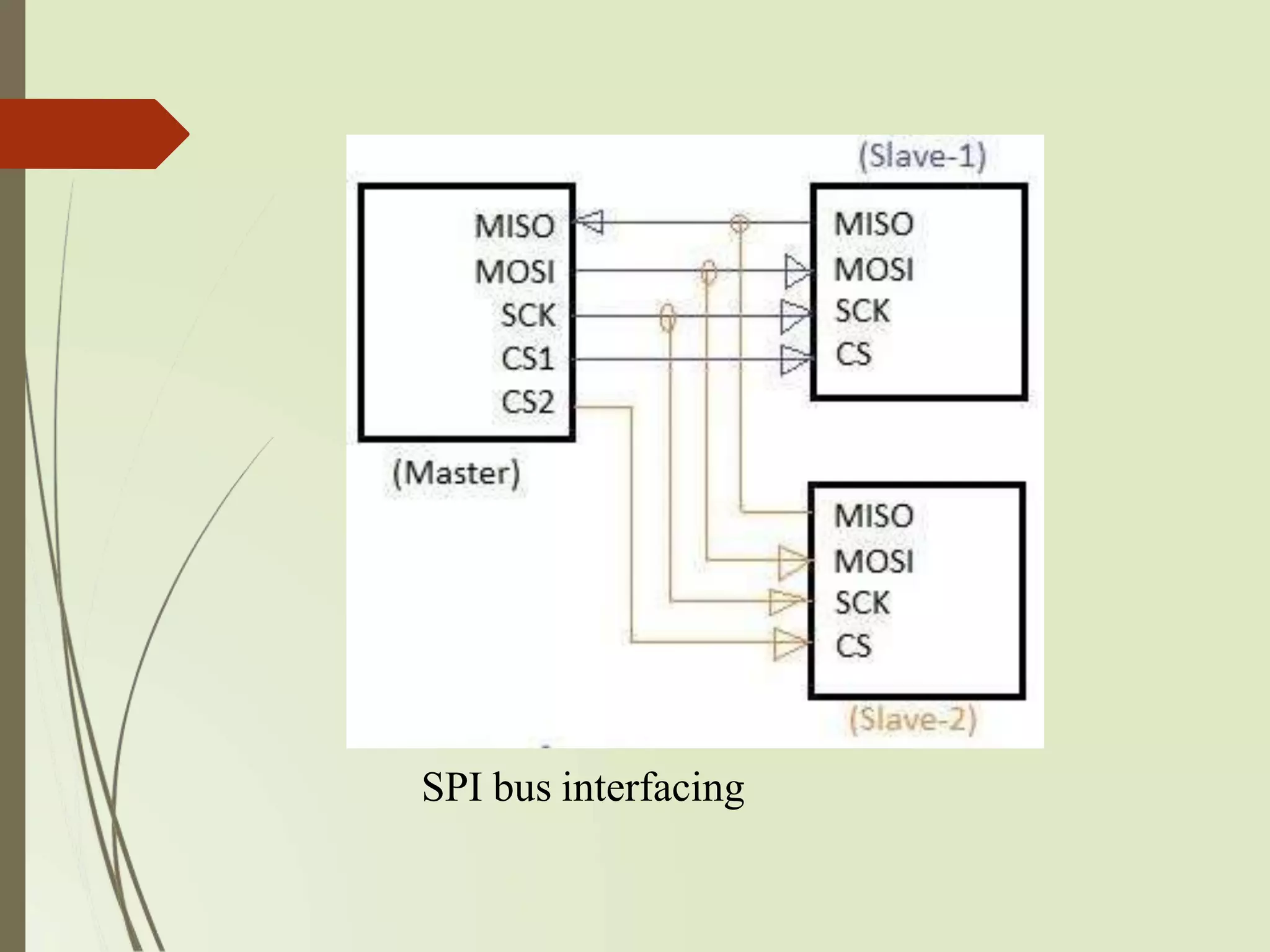
Serial Peripheral Interface(SPI) Bus
The Serial Peripheral Interface Bus (SPI) is a synchronous bi-
directional full duplex four-wire serial interfacebus.
SPI is a single master multi-slave system.
SPI requires four signal lines for communication. They are Master Out
Slave In (MOSI), Master In Slave Out (MISO), Serial Clock (SCLK)
and Slave Select (SS).
When compared to I2C, SPI bus is most suitable for applications
requiring transfer of data in ‘streams’.
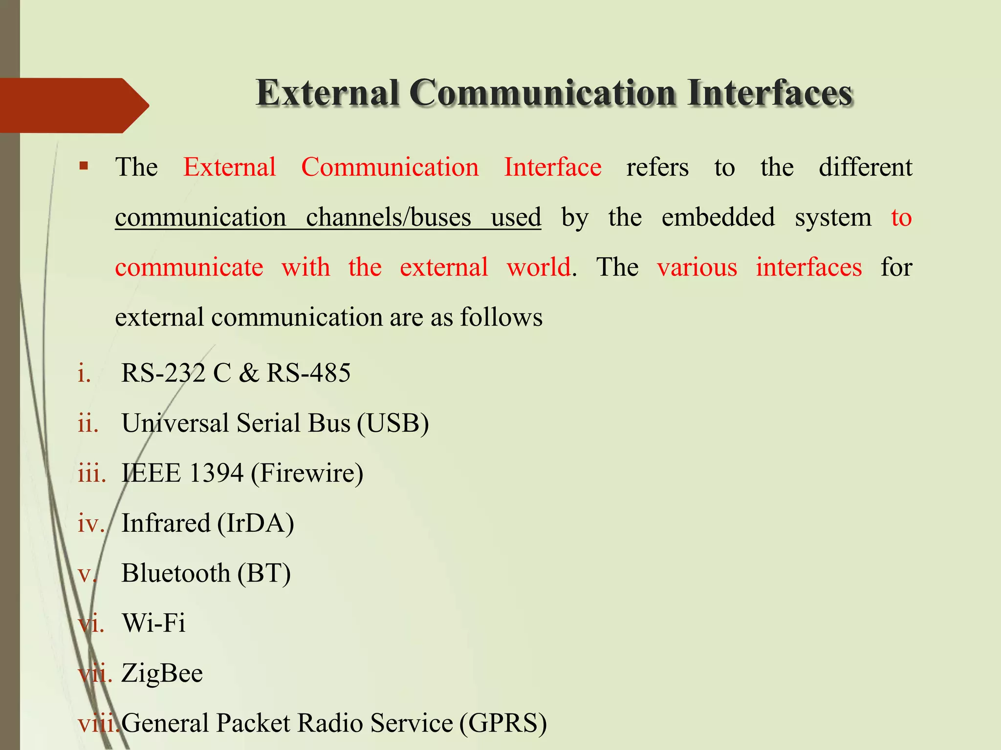
External Communication Interfaces
The External Communication Interface refers to the different
communication channels/buses used by the embedded system to
communicate with the external world. The various interfaces for
external communication are as follows
i. RS-232 C & RS-485
ii. Universal Serial Bus (USB)
iii. IEEE 1394 (Firewire)
iv. Infrared (IrDA)
v. Bluetooth (BT)
vi. Wi-Fi
vii. ZigBee
viii.General Packet Radio Service (GPRS)
95.
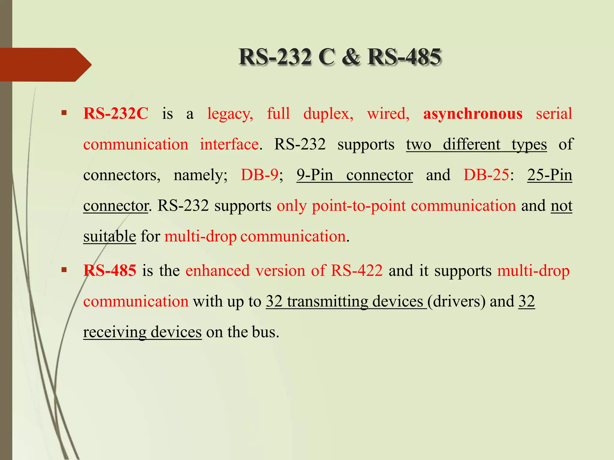
RS-232 C &RS-485
RS-232C is a legacy, full duplex, wired, asynchronous serial
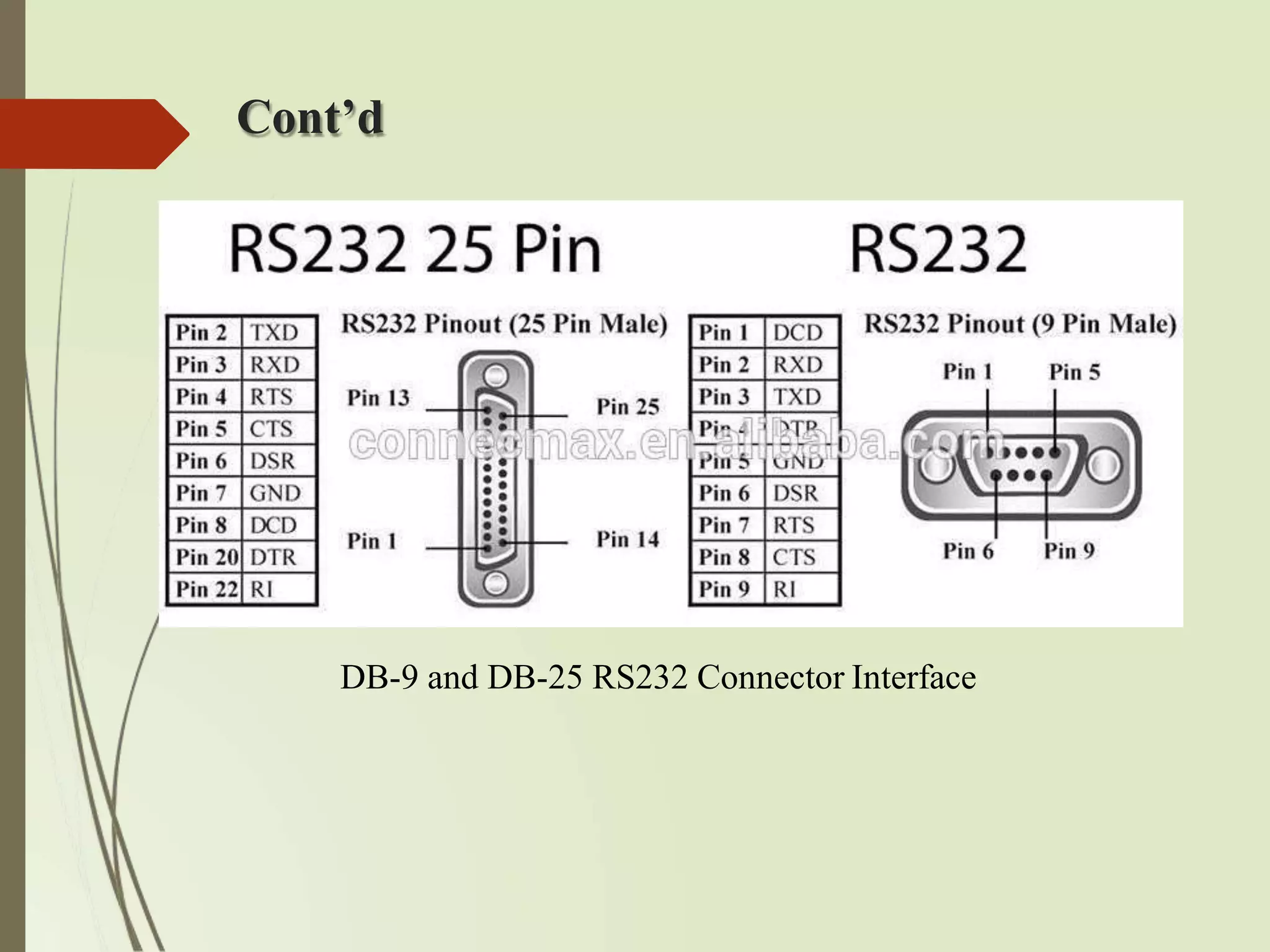
communication interface. RS-232 supports two different types of
connectors, namely; DB-9; 9-Pin connector and DB-25: 25-Pin
connector. RS-232 supports only point-to-point communication and not
suitable for multi-drop communication.
RS-485 is the enhanced version of RS-422 and it supports multi-drop
communication with up to 32 transmitting devices (drivers) and 32
receiving devices on the bus.
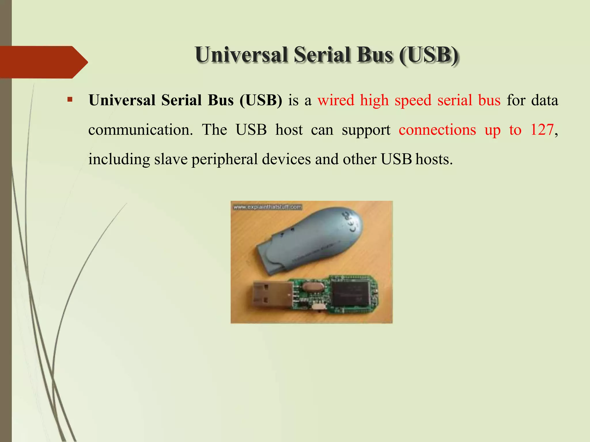
Universal Serial Bus(USB)
Universal Serial Bus (USB) is a wired high speed serial bus for data
communication. The USB host can support connections up to 127,
including slave peripheral devices and other USB hosts.
98.
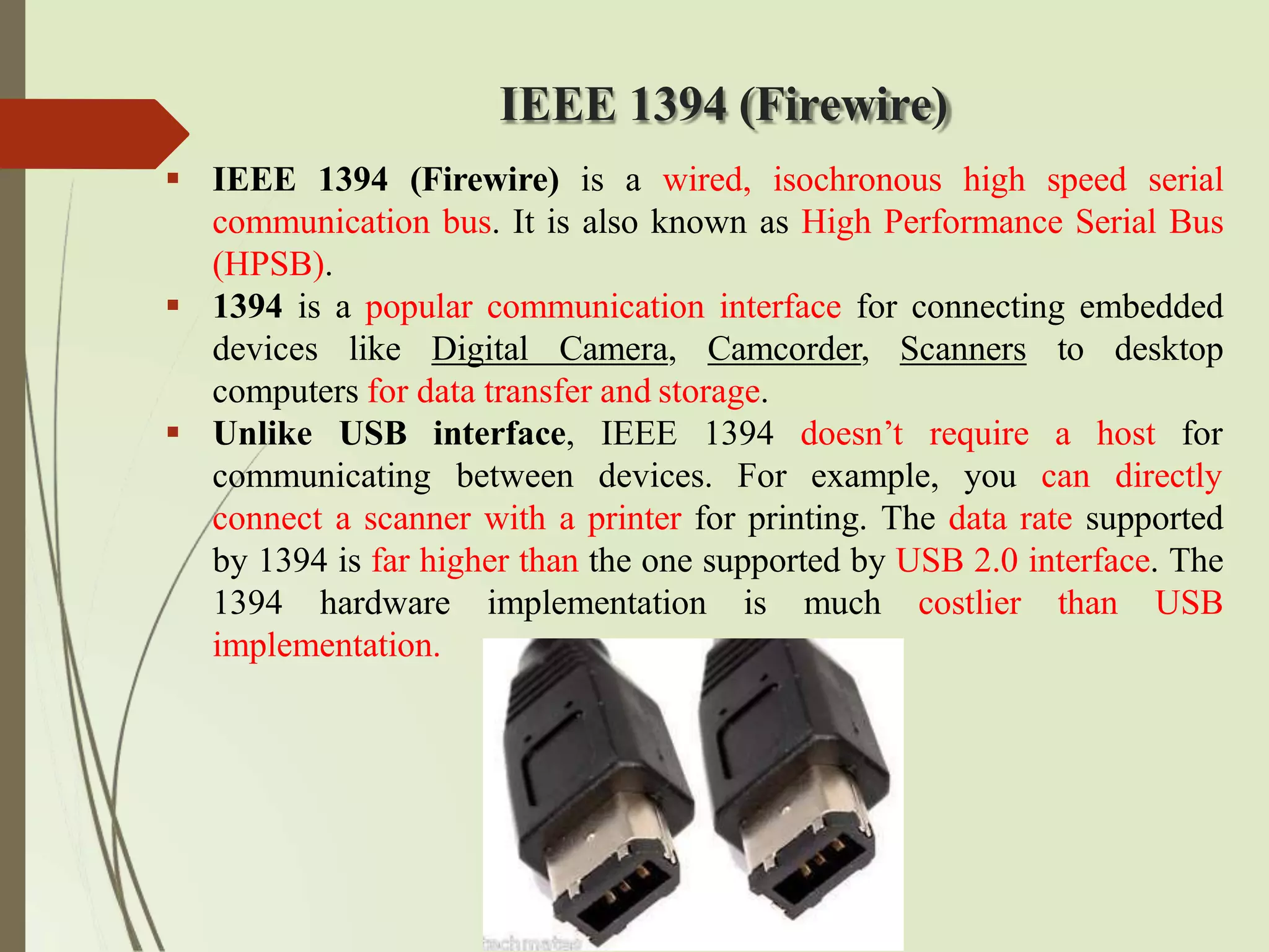
IEEE 1394 (Firewire)
IEEE 1394 (Firewire) is a wired, isochronous high speed serial
communication bus. It is also known as High Performance Serial Bus
(HPSB).
1394 is a popular communication interface for connecting embedded
devices like Digital Camera, Camcorder, Scanners to desktop
computers for data transfer and storage.
communicating
Unlike USB interface, IEEE 1394 doesn’t require
between devices. For example, you
a host for
can directly
connect a scanner with a printer for printing. The data rate supported
by 1394 is far higher than the one supported by USB 2.0 interface. The
1394 hardware implementation is much costlier than USB
implementation.
99.
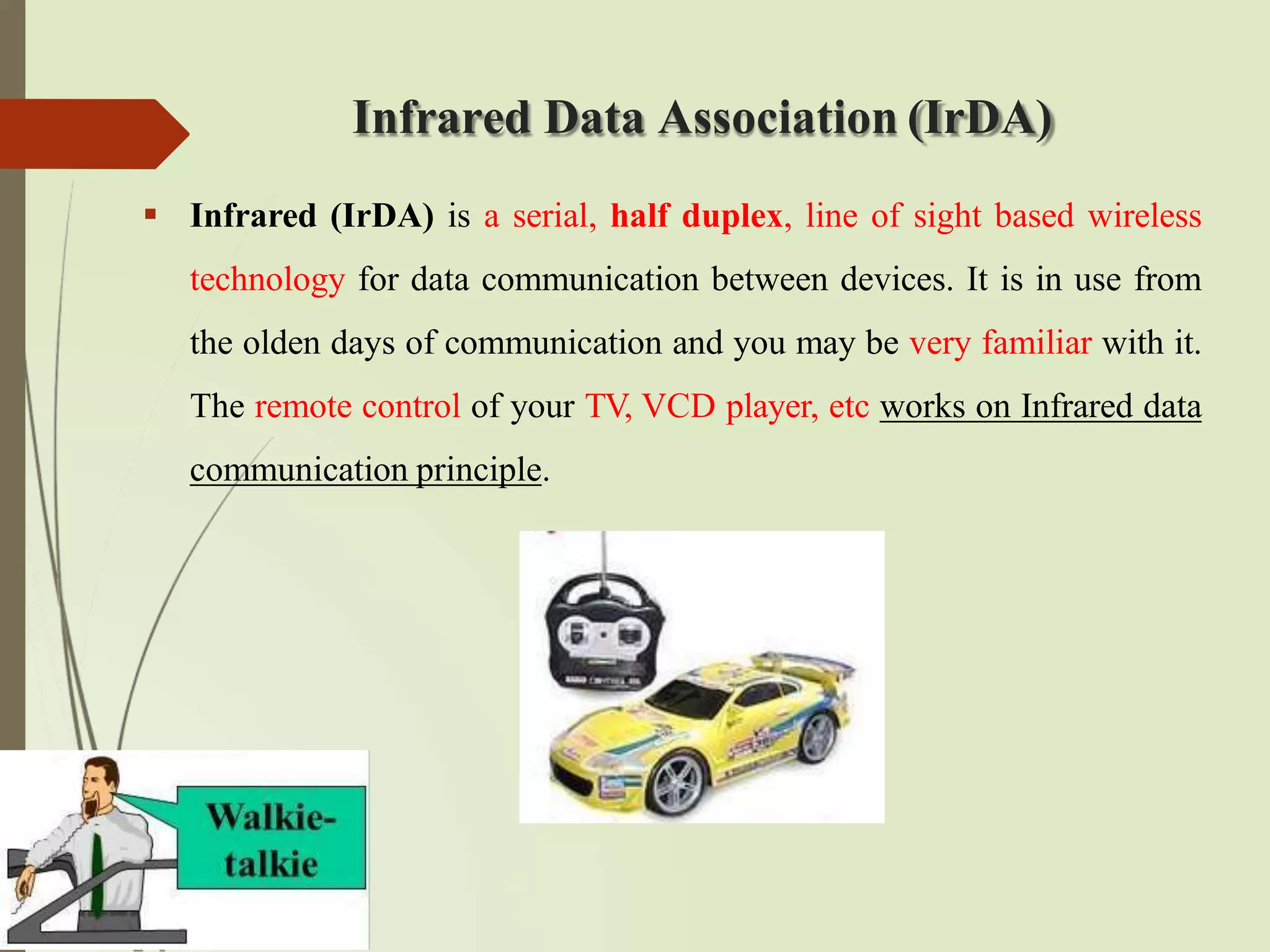
Infrared Data Association(IrDA)
Infrared (IrDA) is a serial, half duplex, line of sight based wireless
technology for data communication between devices. It is in use from
the olden days of communication and you may be very familiar with it.
The remote control of your TV, VCD player, etc works on Infrared data
communication principle.
100.
Bluetooth (BT)
Bluetooth isa low cost, low power, short range wireless technology
for data and voice communication. Bluetooth supports point-to-
point (device to device) and point-to-multipoint (device to multiple
device broadcasting) wireless communication.
A Bluetooth device can function as either master or slave. When a
network is formed with one Bluetooth device as master and more
than one device as slaves, it is called a Piconet. A Piconet supports
a maximum of seven slave devices.
Bluetooth is the favorite choice for short range data communication
in handheld embedded devices. Bluetooth technology is very
popular among cell phone users as they are the easiest
communication channel for transferring ringtones, music
files, pictures, media files, etc. between neighboring
Bluetooth enabled phones.
It supports a data rate of up to 1 Mbps and a range of approximately
30 feet for data communication.
101.
Wi-Fi
Wi-Fi orWireless Fidelity is the popular wireless communication
technique for networked communication of devices. Wi-Fi is intended
for network communication and it supports Internet Protocol (IP) based
communication. It is essential to have device identities in a multipoint
communication to address specific devices for data communication.
Wi-Fi based communications require an intermediate agent called
Wi-Fi router/Wireless access point to manage the communications. Wi-
Fi supports data rates ranging from 1 Mbps to 150 Mbps and offers a
range of 100 to 300 feet.
102.
ZigBee
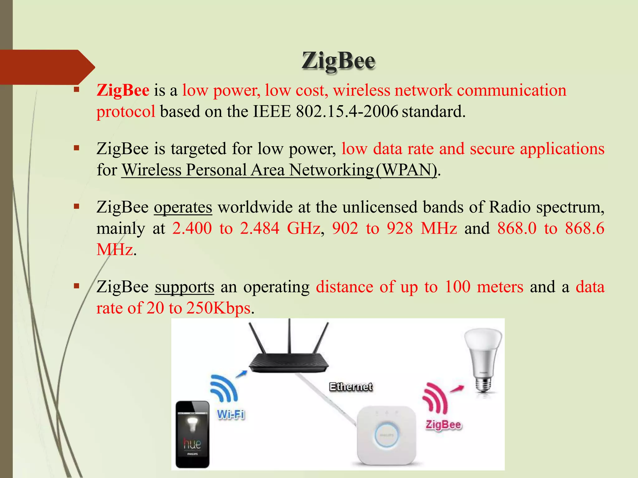
ZigBee isa low power, low cost, wireless network communication
protocol based on the IEEE 802.15.4-2006 standard.
ZigBee is targeted for low power, low data rate and secure applications
for Wireless Personal Area Networking(WPAN).
ZigBee operates worldwide at the unlicensed bands of Radio spectrum,
mainly at 2.400 to 2.484 GHz, 902 to 928 MHz and 868.0 to 868.6
MHz.
ZigBee supports an operating distance of up to 100 meters and a data
rate of 20 to 250Kbps.
103.
Cont’d
ZigBee device categoriesare as follows:
ZigBee Coordinator (ZC)/Network Coordinator: The ZigBee coordinator
acts as the root of the ZigBee network. The ZC is responsible for initiating the
ZigBee network and it has the capability to store information about the
network.
ZigBee Router (ZR)/Full Function Device (FFD): Responsible for passing
information from device to another device or to another ZR.
ZigBee End Device (ZED)/Reduced Function Device (RFD): End device
containing ZigBee functionality for data communication.
104.
General Packet RadioService (GPRS)
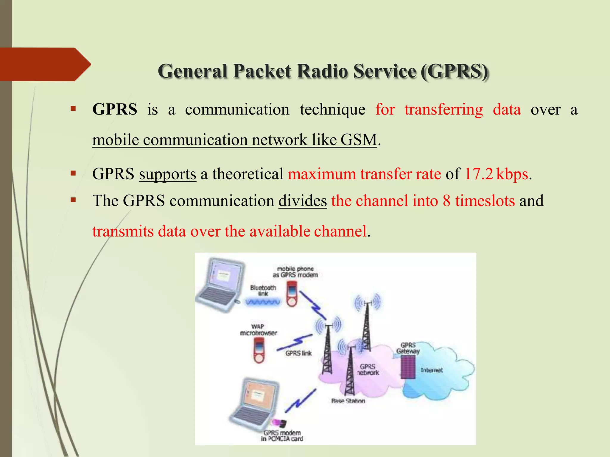
GPRS is a communication technique for transferring data over a
mobile communication network like GSM.
GPRS supports a theoretical maximum transfer rate of 17.2kbps.
The GPRS communication divides the channel into 8 timeslots and
transmits data over the available channel.
105.
2.5 Embedded Firmware
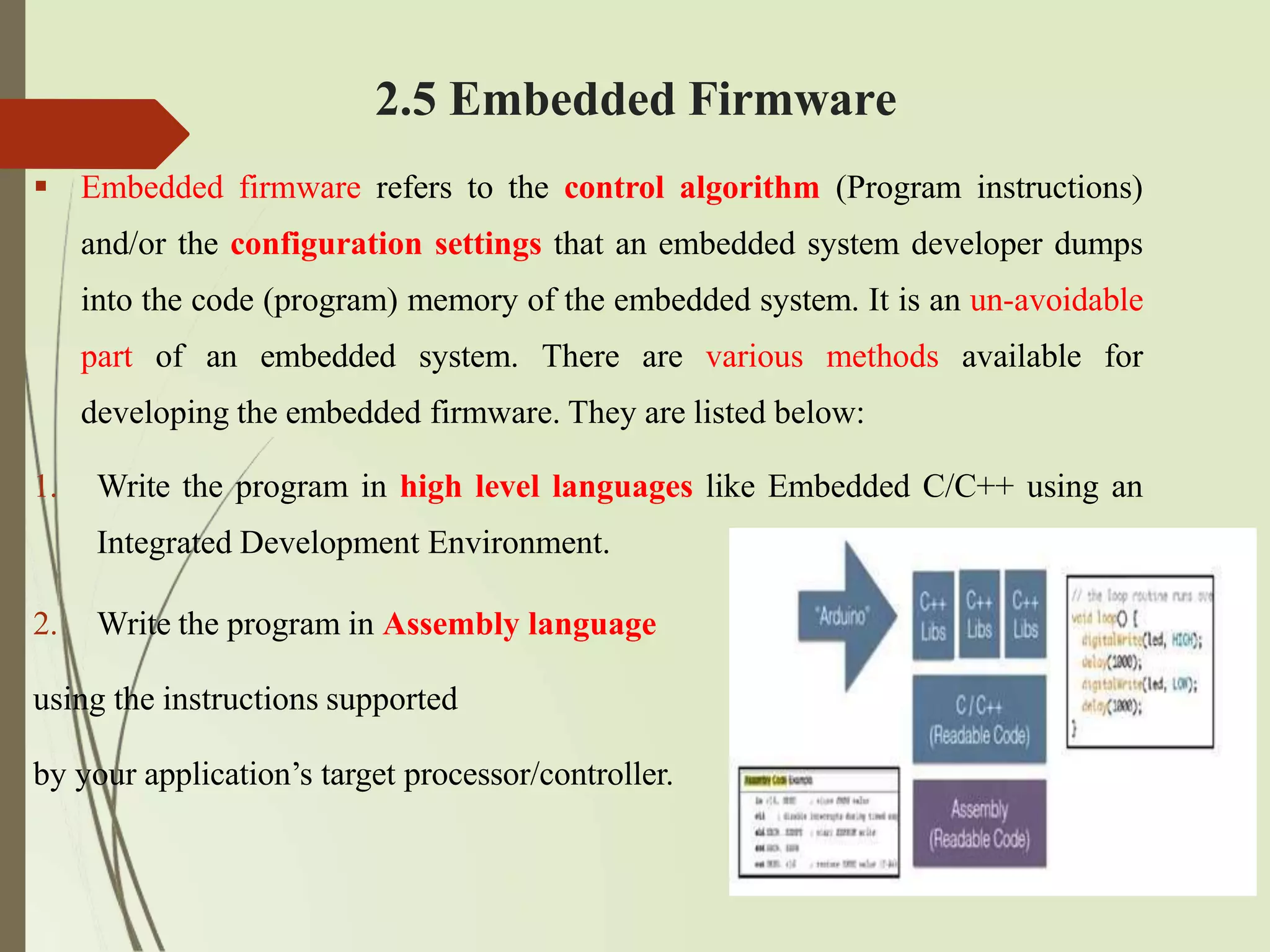
Embedded firmware refers to the control algorithm (Program instructions)
and/or the configuration settings that an embedded system developer dumps
into the code (program) memory of the embedded system. It is an un-avoidable
part of an embedded system. There are various methods available for
developing the embedded firmware. They are listed below:
1. Write the program in high level languages like Embedded C/C++ using an
Integrated Development Environment.
2. Write the program in Assembly language
using the instructions supported
by your application’s target processor/controller.
106.
Cont’d
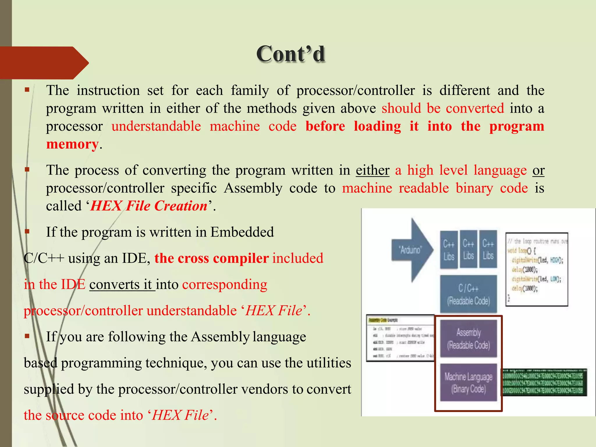
The instructionset for each family of processor/controller is different and the
program written in either of the methods given above should be converted into a
processor understandable machine code before loading it into the program
memory.
The process of converting the program written in either a high level language or
processor/controller specific Assembly code to machine readable binary code is
called ‘HEX File Creation’.
If the program is written in Embedded
C/C++ using an IDE, the cross compiler included
in the IDE converts it into corresponding
processor/controller understandable ‘HEX File’.
If you are following the Assembly language
based programming technique, you can use the utilities
supplied by the processor/controller vendors to convert
the source code into ‘HEX File’.
107.
2.6 Other SystemComponents
The other system components refer to the components/circuits/ICs
which are necessary for the proper functioning of the embedded
system.
Reset Circuit, Brown-out Protection Circuit, Oscillator Unit, Real-
Time Clock (RTC), Watchdog Timer are examples of circuits/ICs
which are essential for the proper functioning of the
processor/controllers.
108.
Reset Circuit
Thereset circuit is essential to ensure that the device is not operating at a voltage level where
the device is not guaranteed to operate, during system power ON. The reset signal brings
the internal registers and the different hardware systems of the processor/controller to a
known state and starts the firmware execution from the reset vector.
The reset signal can be either active high (The processor undergoes reset when the reset pin
of the processor is at logic high) or active low (The processor undergoes reset when the reset
pin of the processor is at logic low). Since the processor operation is synchronized to a clock
signal, the reset pulse should be wide enough to give time for the clock oscillator to
stabilize before the internal reset state starts.
Some microprocessors/controllers contain built-in internal reset circuitry and they don’t
require external reset circuitry. Figure illustrates a resistor capacitor based passive reset
circuit for active high and low configurations. The reset pulse width can be adjusted by
changing the resistance value R and capacitance value C.
109.
Brown-out Protection Circuit
The brown-out protection circuit prevents the processor/controller
from unexpected program execution behavior when the supply
voltage to the processor/controller falls below a specified voltage.
Oscillator
The Oscillator unit generates clock signals for synchronizing the
operations of the processor.
110.
Real-Time Clock (RTC)
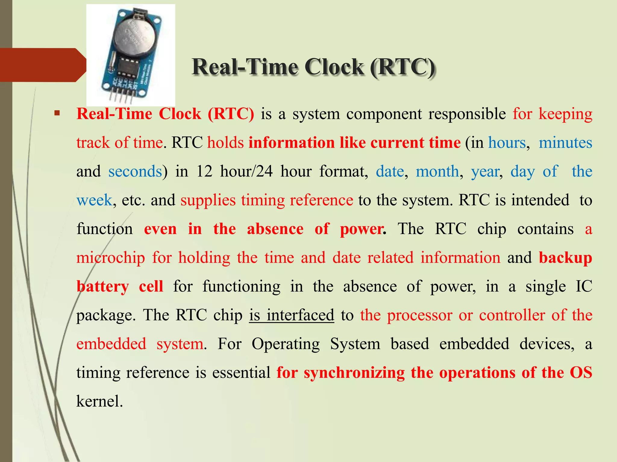
Real-Time Clock (RTC) is a system component responsible for keeping
track of time. RTC holds information like current time (in hours, minutes
and seconds) in 12 hour/24 hour format, date, month, year, day of the
week, etc. and supplies timing reference to the system. RTC is intended to
function even in the absence of power. The RTC chip contains a
microchip for holding the time and date related information and backup
battery cell for functioning in the absence of power, in a single IC
package. The RTC chip is interfaced to the processor or controller of the
embedded system. For Operating System based embedded devices, a
timing reference is essential for synchronizing the operations of the OS
kernel.
111.
Watchdog Timer
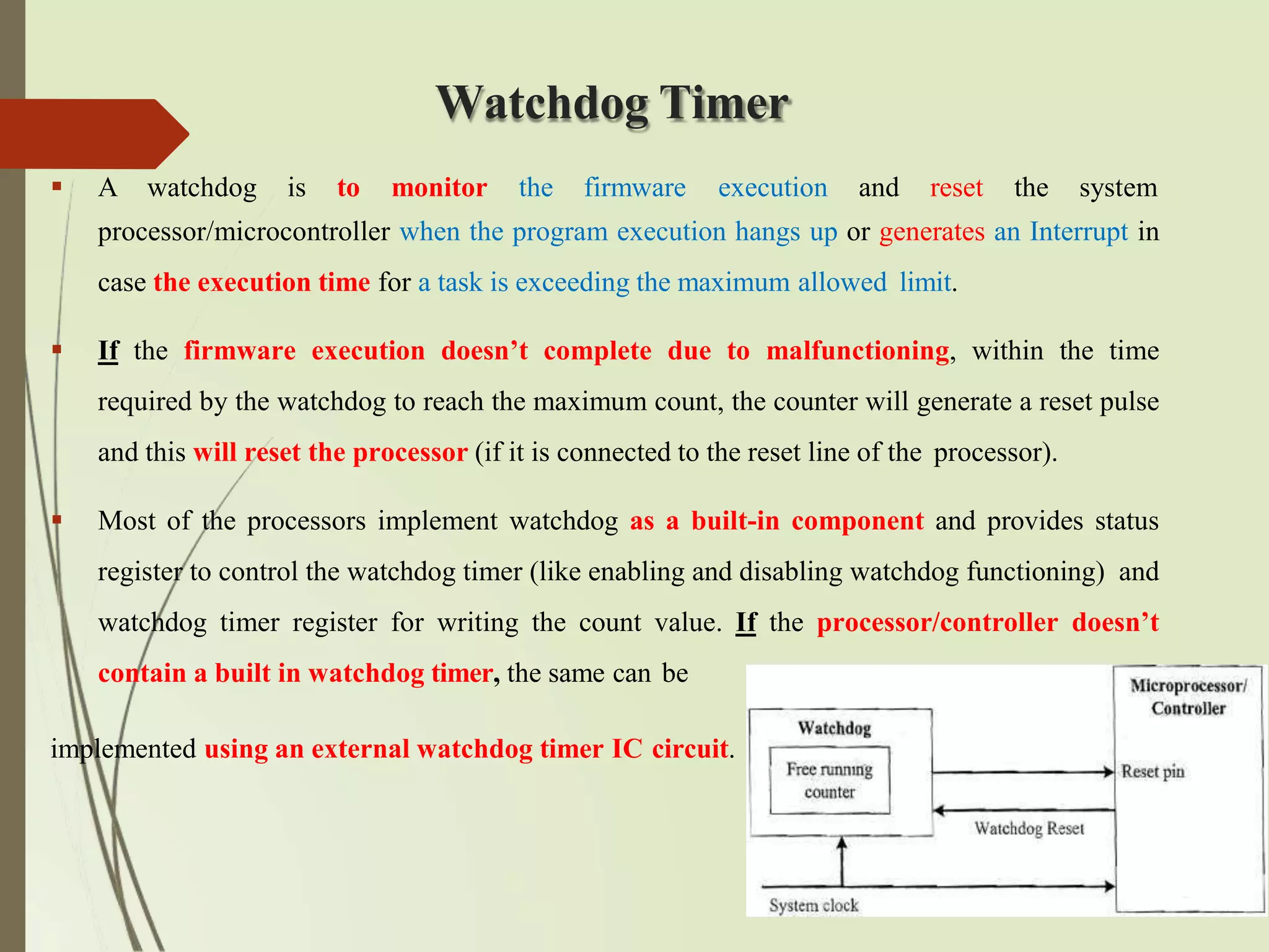
Awatchdog is to monitor the firmware execution and reset the system
processor/microcontroller when the program execution hangs up or generates an Interrupt in
case the execution time for a task is exceeding the maximum allowed limit.
If the firmware execution doesn’t complete due to malfunctioning, within the time
required by the watchdog to reach the maximum count, the counter will generate a reset pulse
and this will reset the processor (if it is connected to the reset line of the processor).
Most of the processors implement watchdog as a built-in component and provides status
register to control the watchdog timer (like enabling and disabling watchdog functioning) and
watchdog timer register for writing the count value. If the processor/controller doesn’t
contain a built in watchdog timer, the same can be
implemented using an external watchdog timer IC circuit.
112.
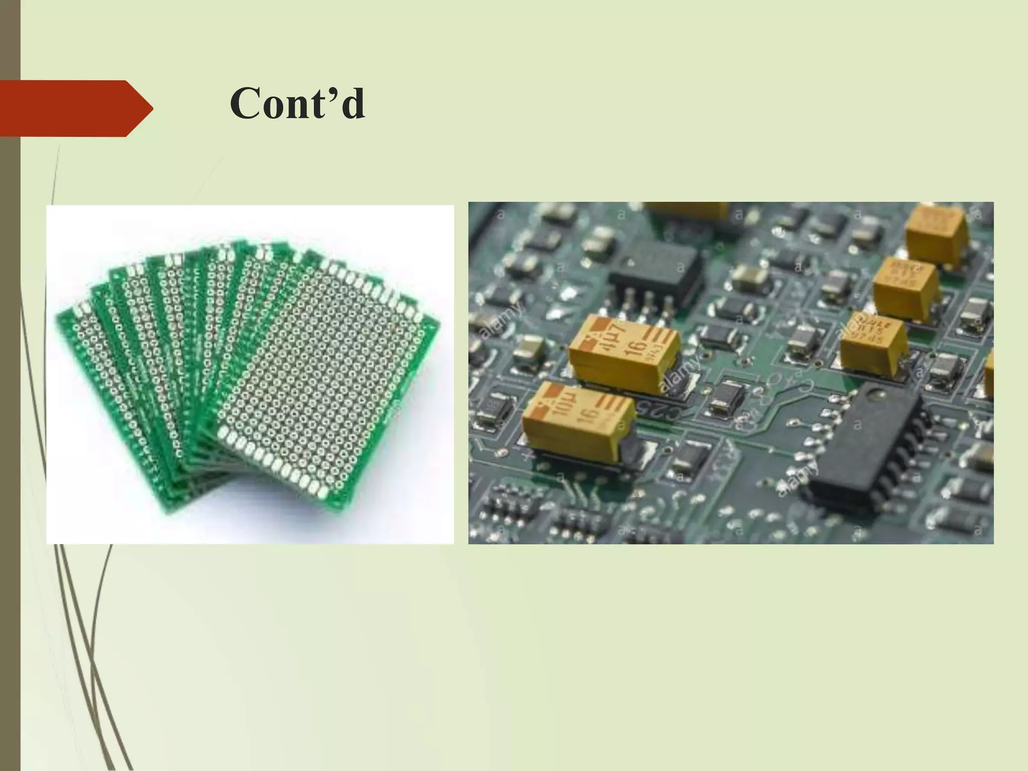
PCB and PassiveComponents
Printed Circuit Board (PCB) is the backbone of every embedded
system. After finalizing the components and the inter-connection
among them, a schematic design is created and according to the schematic
PCB is fabricated. PCS acts as a platform for mounting all the
necessary components as per the design requirement. Also it acts as a
platform for testing your embedded firmware. You can also find some
passive electronic components like resistor, capacitor, diodes, etc. on your
board. They are the co-workers of various chips contained in your
embedded hardware. They are very essential for the proper functioning of
your embedded system.
Design challenge –optimizing design
metrics
• Design goal:
– Construct an implementation with desired
functionality
• Key design challenge:
– Simultaneously optimize numerous design metrics
• Design metric
– A measurable feature of a system’s
implementation
– Optimizing design metrics is a key challenge
115.
Design challenge –optimizing design
metrics
• Common metrics
– Unit cost: the monetary cost of manufacturing each copy of the system,
excluding NRE cost
– NRE cost (Non-Recurring Engineering cost): The one-
time monetary cost of designing the system
– Size: the physical space required by the system
– Performance: the execution time or throughput of the system
– Power: the amount of power consumed by the system
– Flexibility: the ability to change the functionality of the system without
incurring heavy NRE cost
116.
Design challenge –optimizing design
metrics
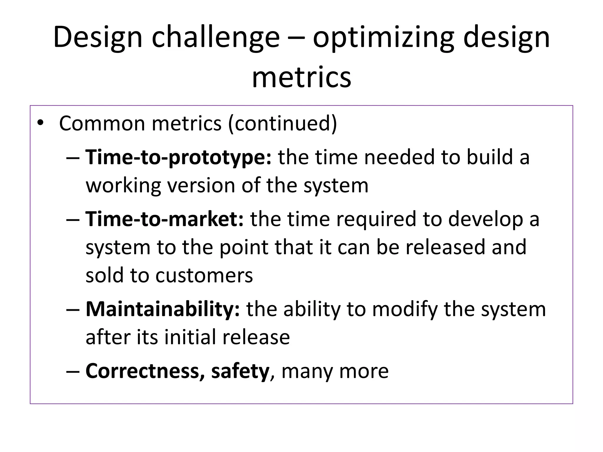
• Common metrics (continued)
– Time-to-prototype: the time needed to build a
working version of the system
– Time-to-market: the time required to develop a
system to the point that it can be released and
sold to customers
– Maintainability: the ability to modify the system
after its initial release
– Correctness, safety, many more
117.
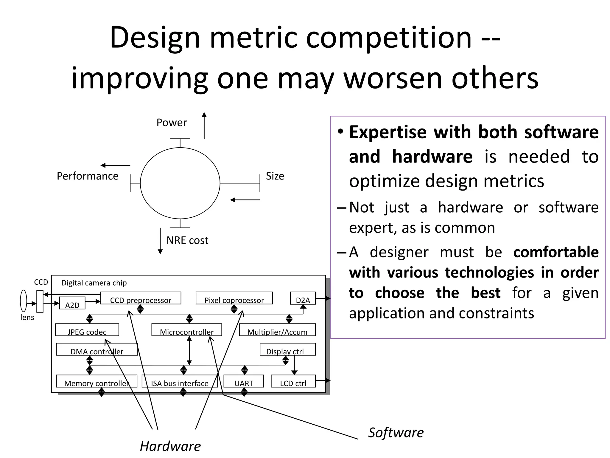
Design metric competition--
improving one may worsen others
• Expertise with both software
and hardware is needed to
optimize design metrics
– Not just a hardware or software
expert, as is common
– A designer must be comfortable
with various technologies in order
to choose the best for a given
application and constraints
Size
Performance
Power
NRE cost
Microcontroller
CCD preprocessor Pixel coprocessor
A2D
D2A
JPEG codec
DMA controller
Memory controller ISA bus interface UART LCD ctrl
Display ctrl
Multiplier/Accum
Digital camera chip
lens
CCD
Hardware
Software
118.
Time-to-market: a demandingdesign
metric
• Time to Market:
• Time required to develop a
product to the point it can
be sold to customers
• Market window
– Period during which the
product would have highest
sales
• Average time-to-market
constraint is about 8
months
• Delays can be costly
Revenues
($)
Time (months / weeks)
119.
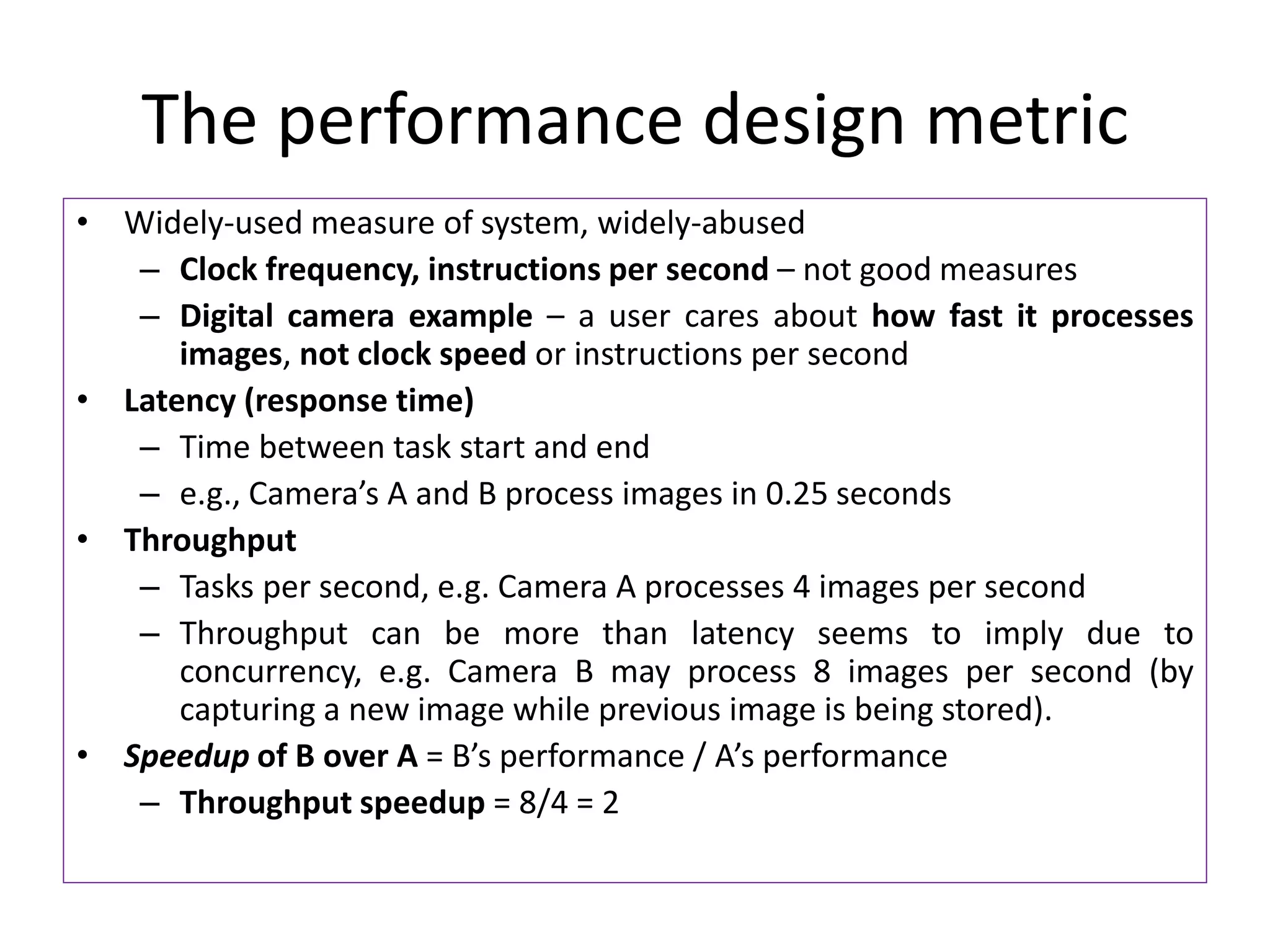
The performance designmetric
• Widely-used measure of system, widely-abused
– Clock frequency, instructions per second – not good measures
– Digital camera example – a user cares about how fast it processes
images, not clock speed or instructions per second
• Latency (response time)
– Time between task start and end
– e.g., Camera’s A and B process images in 0.25 seconds
• Throughput
– Tasks per second, e.g. Camera A processes 4 images per second
– Throughput can be more than latency seems to imply due to
concurrency, e.g. Camera B may process 8 images per second (by
capturing a new image while previous image is being stored).
• Speedup of B over A = B’s performance / A’s performance
– Throughput speedup = 8/4 = 2
120.
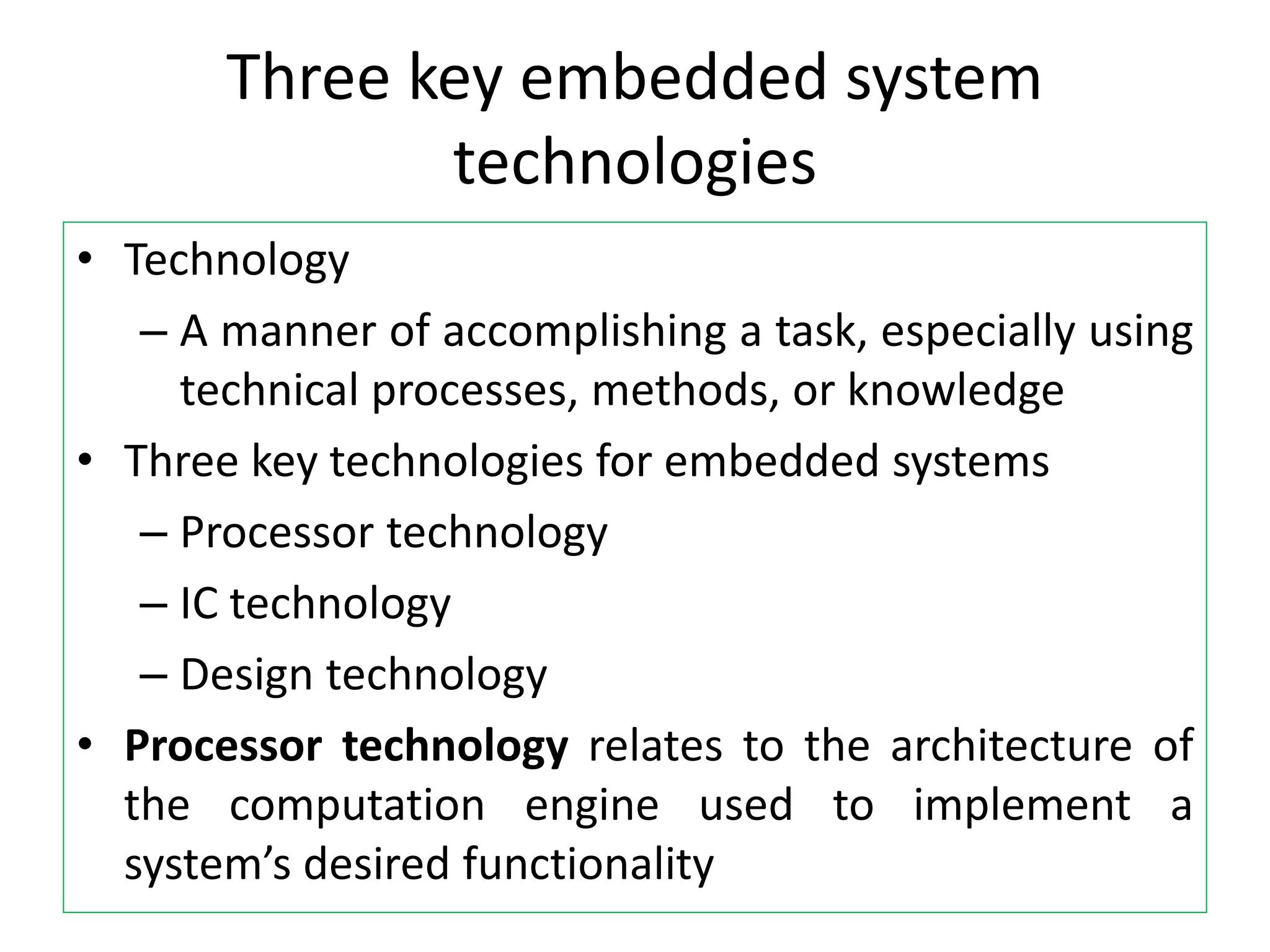
Three key embeddedsystem
technologies
• Technology
– A manner of accomplishing a task, especially using
technical processes, methods, or knowledge
• Three key technologies for embedded systems
– Processor technology
– IC technology
– Design technology
• Processor technology relates to the architecture of
the computation engine used to implement a
system’s desired functionality
121.
Processor technology
• Processorsvary in their customization for the problem at hand
• Example: Summing of the items in an array
total = 0
for i = 1 to N loop
total += M[i]
end loop
General-purpose
processor
Single-purpose
processor
(ASIC)
Application-specific
Instruction set (ASIP)
processor
Desired
functionality
122.
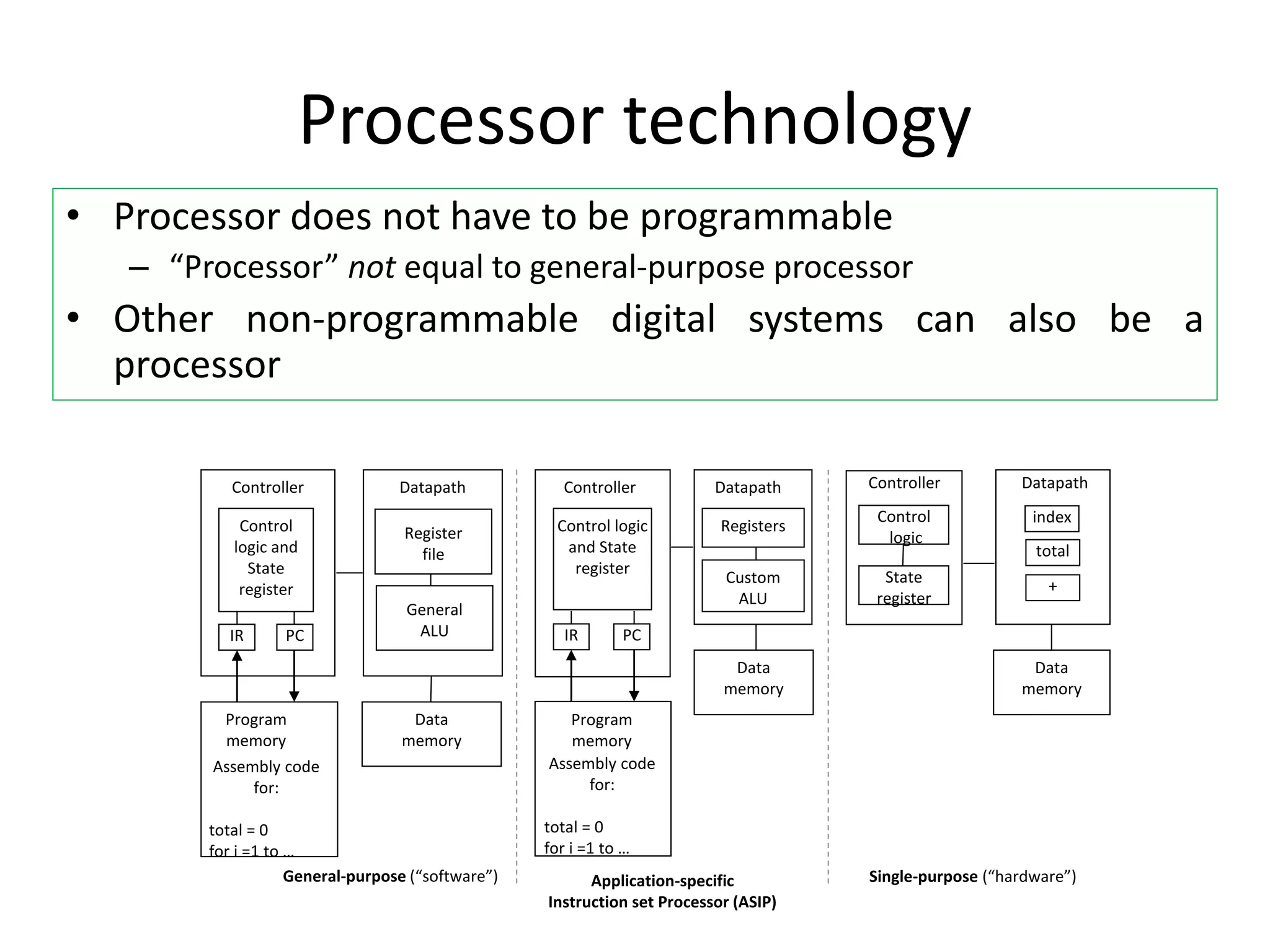
Processor technology
• Processordoes not have to be programmable
– “Processor” not equal to general-purpose processor
• Other non-programmable digital systems can also be a
processor
Application-specific
Instruction set Processor (ASIP)
Registers
Custom
ALU
Datapath
Controller
Program
memory
Assembly code
for:
total = 0
for i =1 to …
Control logic
and State
register
Data
memory
IR PC
Single-purpose (“hardware”)
Datapath
Controller
Control
logic
State
register
Data
memory
index
total
+
IR PC
Register
file
General
ALU
Datapath
Controller
Program
memory
Assembly code
for:
total = 0
for i =1 to …
Control
logic and
State
register
Data
memory
General-purpose (“software”)
123.
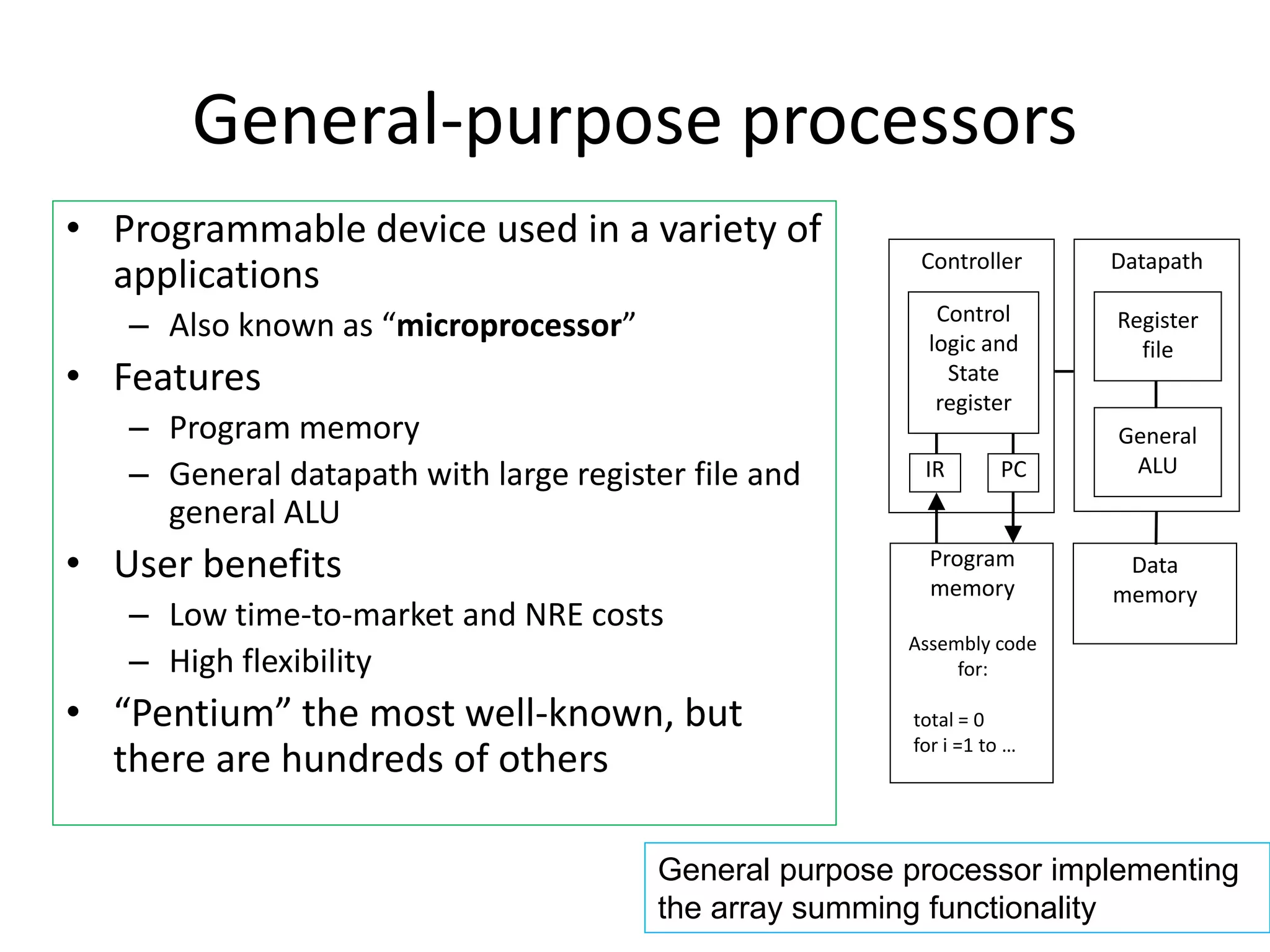
General-purpose processors
• Programmabledevice used in a variety of
applications
– Also known as “microprocessor”
• Features
– Program memory
– General datapath with large register file and
general ALU
• User benefits
– Low time-to-market and NRE costs
– High flexibility
• “Pentium” the most well-known, but
there are hundreds of others
IR PC
Register
file
General
ALU
Datapath
Controller
Program
memory
Assembly code
for:
total = 0
for i =1 to …
Control
logic and
State
register
Data
memory
General purpose processor implementing
the array summing functionality
124.
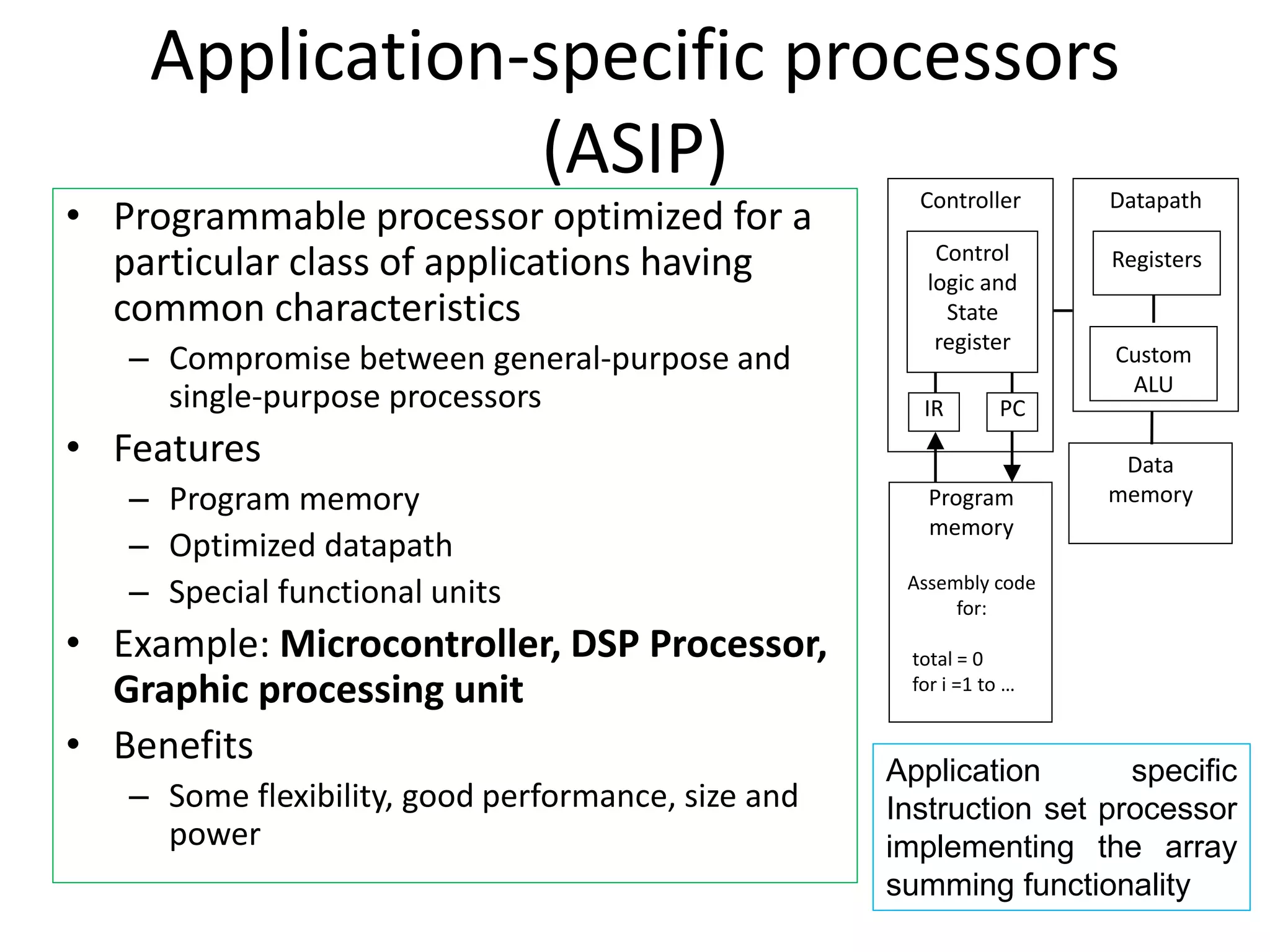
Application-specific processors
(ASIP)
• Programmableprocessor optimized for a
particular class of applications having
common characteristics
– Compromise between general-purpose and
single-purpose processors
• Features
– Program memory
– Optimized datapath
– Special functional units
• Example: Microcontroller, DSP Processor,
Graphic processing unit
• Benefits
– Some flexibility, good performance, size and
power
IR PC
Registers
Custom
ALU
Datapath
Controller
Program
memory
Assembly code
for:
total = 0
for i =1 to …
Control
logic and
State
register
Data
memory
Application specific
Instruction set processor
implementing the array
summing functionality
125.
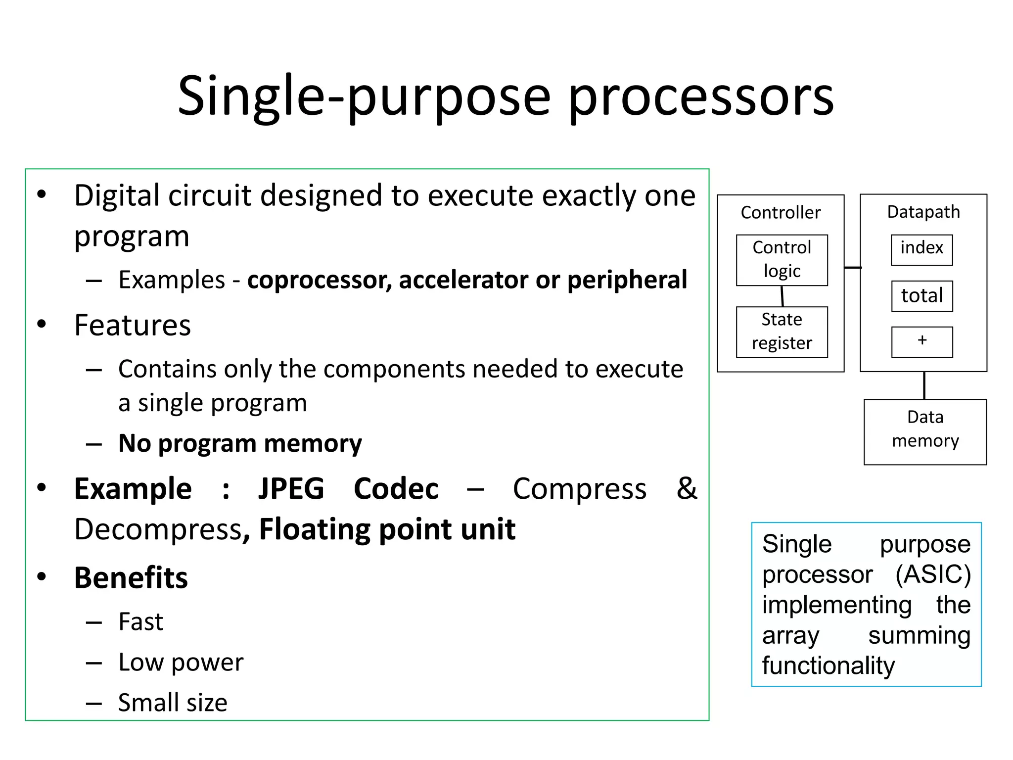
Single-purpose processors
• Digitalcircuit designed to execute exactly one
program
– Examples - coprocessor, accelerator or peripheral
• Features
– Contains only the components needed to execute
a single program
– No program memory
• Example : JPEG Codec – Compress &
Decompress, Floating point unit
• Benefits
– Fast
– Low power
– Small size
Datapath
Controller
Control
logic
State
register
Data
memory
index
total
+
Single purpose
processor (ASIC)
implementing the
array summing
functionality
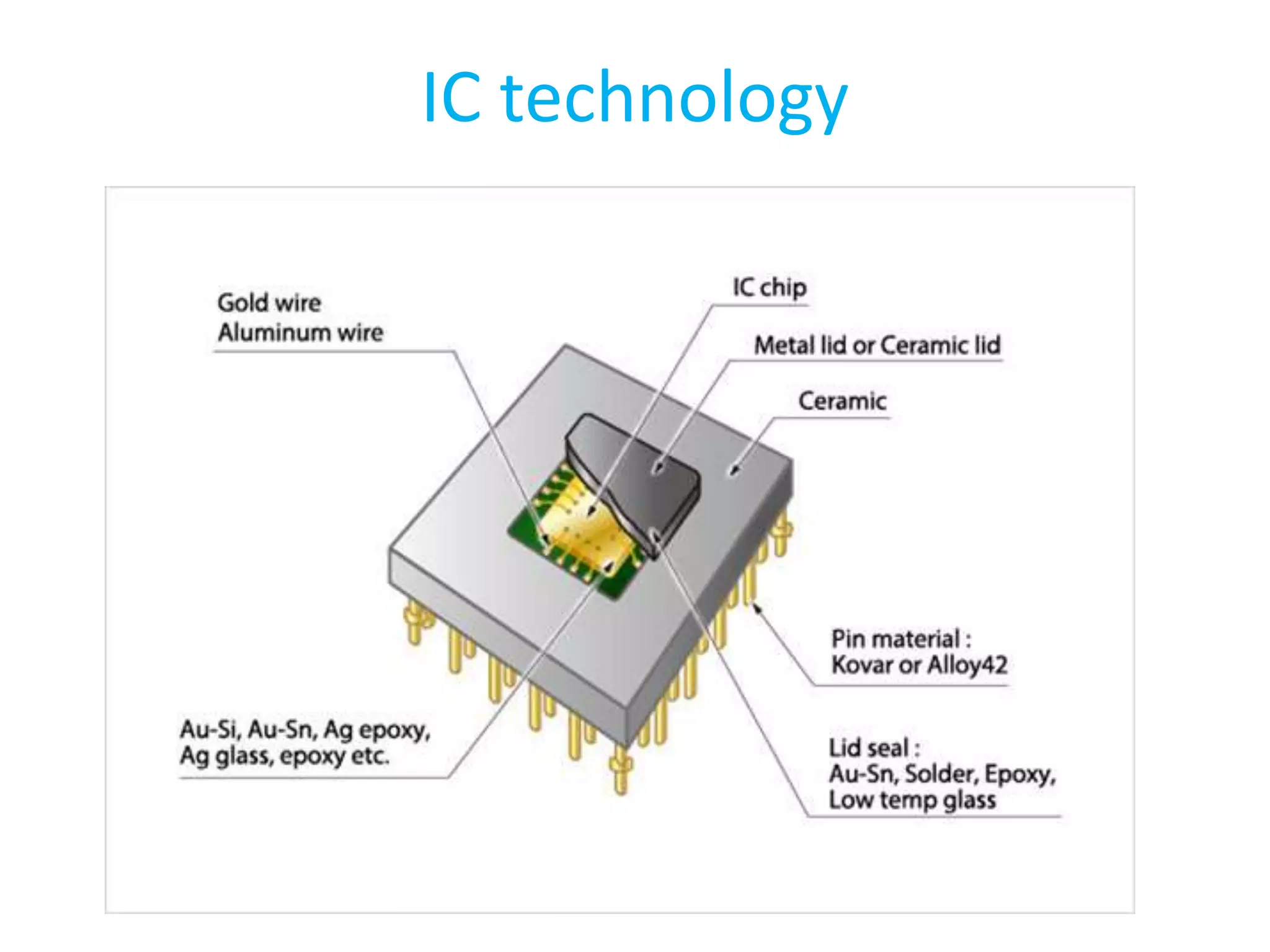
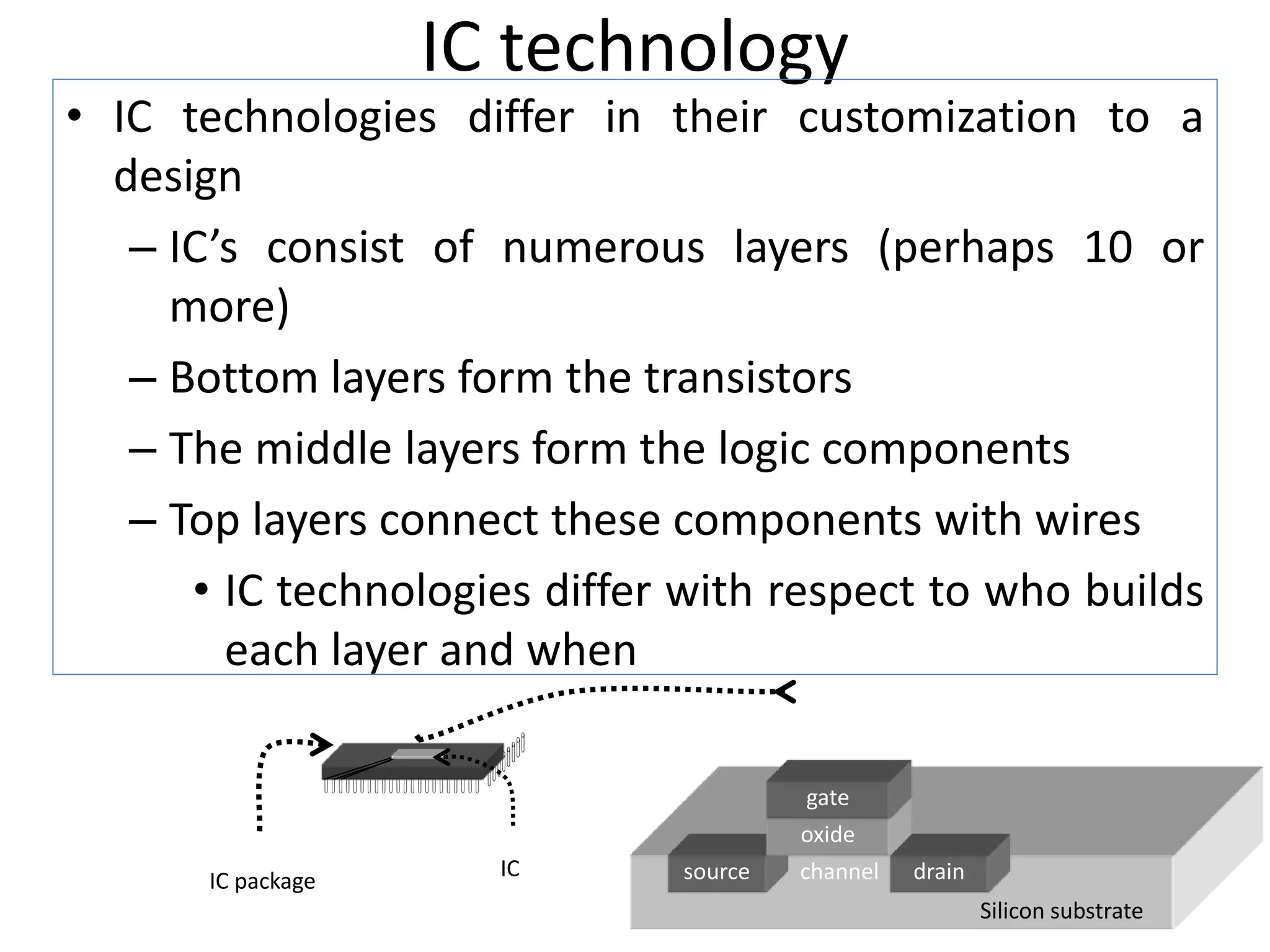
IC technology
• ICtechnologies differ in their customization to a
design
– IC’s consist of numerous layers (perhaps 10 or
more)
– Bottom layers form the transistors
– The middle layers form the logic components
– Top layers connect these components with wires
• IC technologies differ with respect to who builds
each layer and when
source drain
channel
oxide
gate
Silicon substrate
IC package
IC
128.
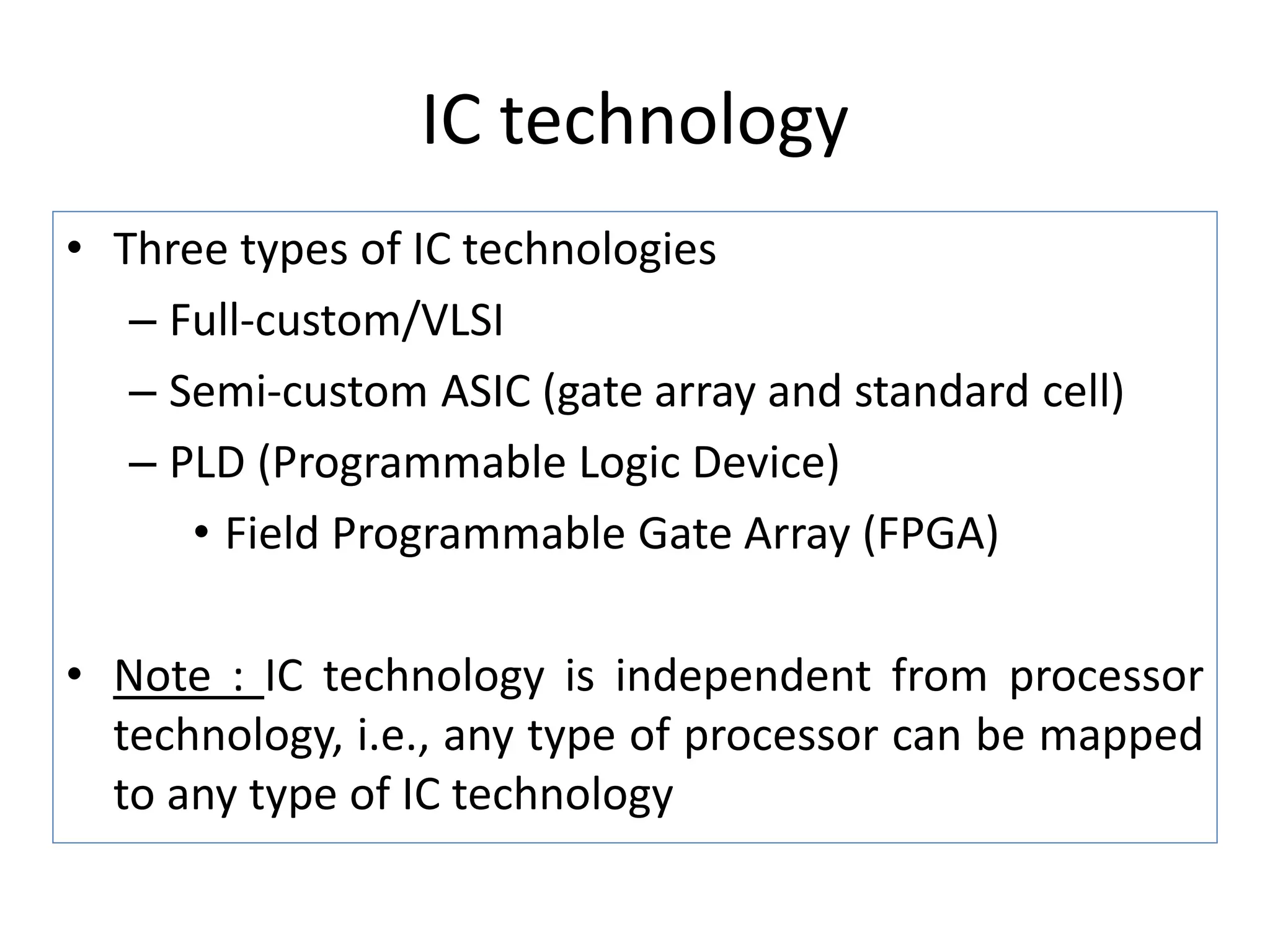
IC technology
• Threetypes of IC technologies
– Full-custom/VLSI
– Semi-custom ASIC (gate array and standard cell)
– PLD (Programmable Logic Device)
• Field Programmable Gate Array (FPGA)
• Note : IC technology is independent from processor
technology, i.e., any type of processor can be mapped
to any type of IC technology
129.
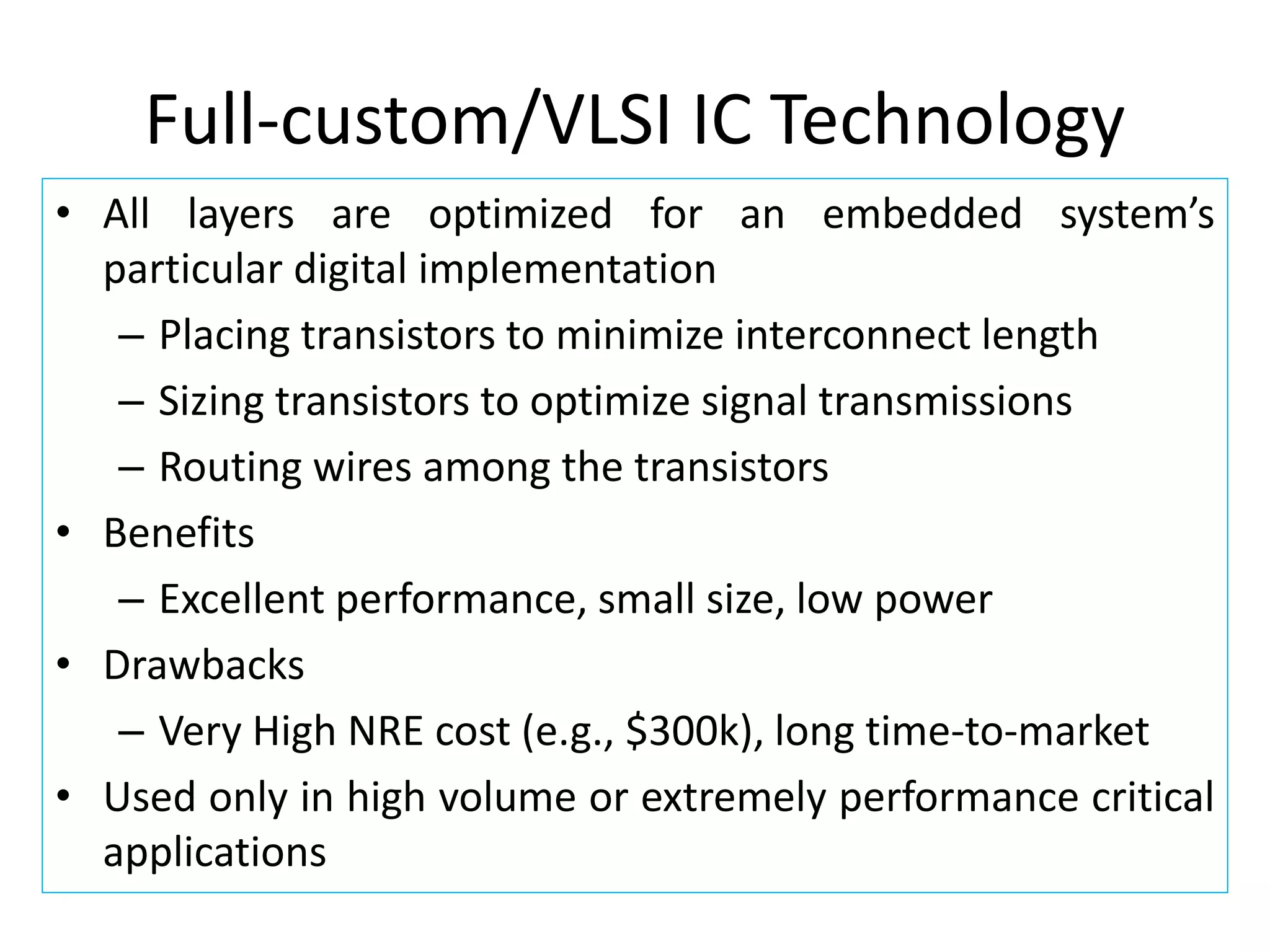
Full-custom/VLSI IC Technology
•All layers are optimized for an embedded system’s
particular digital implementation
– Placing transistors to minimize interconnect length
– Sizing transistors to optimize signal transmissions
– Routing wires among the transistors
• Benefits
– Excellent performance, small size, low power
• Drawbacks
– Very High NRE cost (e.g., $300k), long time-to-market
• Used only in high volume or extremely performance critical
applications
130.
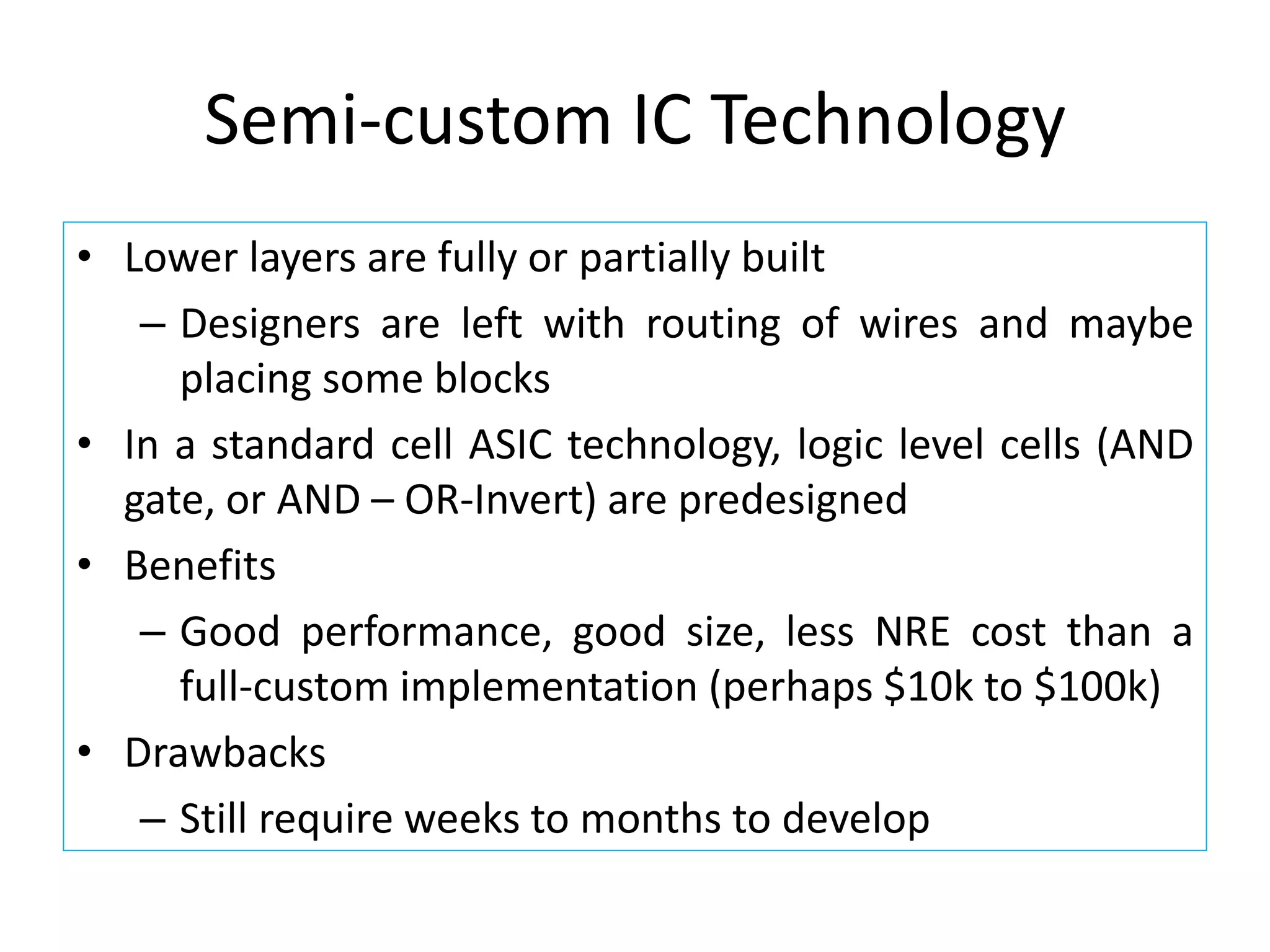
Semi-custom IC Technology
•Lower layers are fully or partially built
– Designers are left with routing of wires and maybe
placing some blocks
• In a standard cell ASIC technology, logic level cells (AND
gate, or AND – OR-Invert) are predesigned
• Benefits
– Good performance, good size, less NRE cost than a
full-custom implementation (perhaps $10k to $100k)
• Drawbacks
– Still require weeks to months to develop
131.
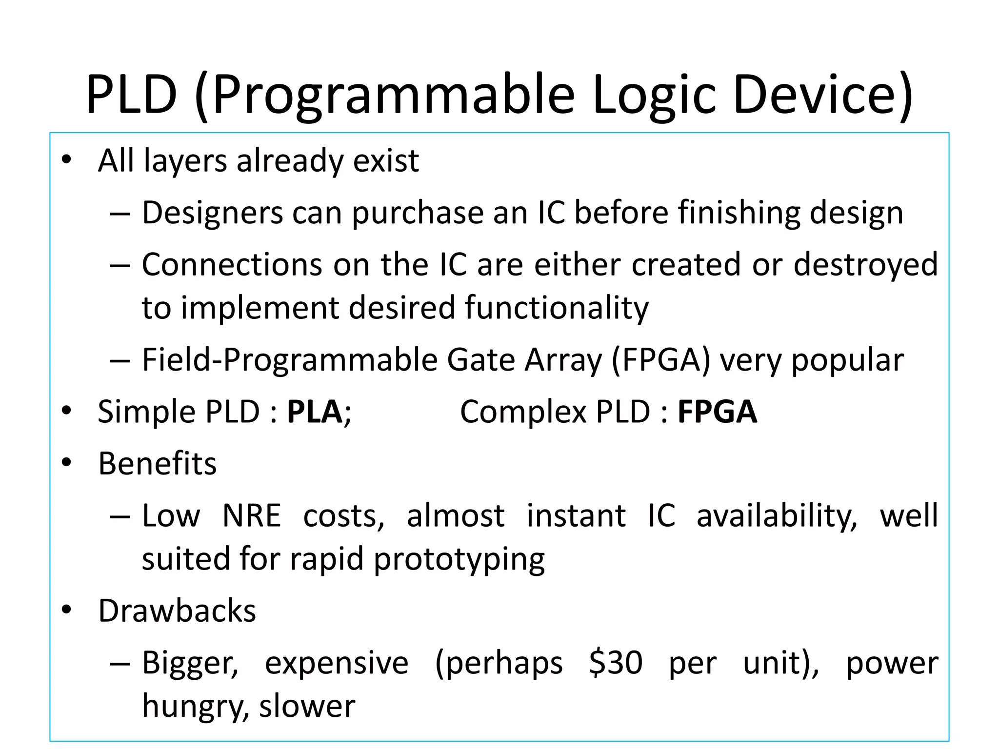
PLD (Programmable LogicDevice)
• All layers already exist
– Designers can purchase an IC before finishing design
– Connections on the IC are either created or destroyed
to implement desired functionality
– Field-Programmable Gate Array (FPGA) very popular
• Simple PLD : PLA; Complex PLD : FPGA
• Benefits
– Low NRE costs, almost instant IC availability, well
suited for rapid prototyping
• Drawbacks
– Bigger, expensive (perhaps $30 per unit), power
hungry, slower
132.
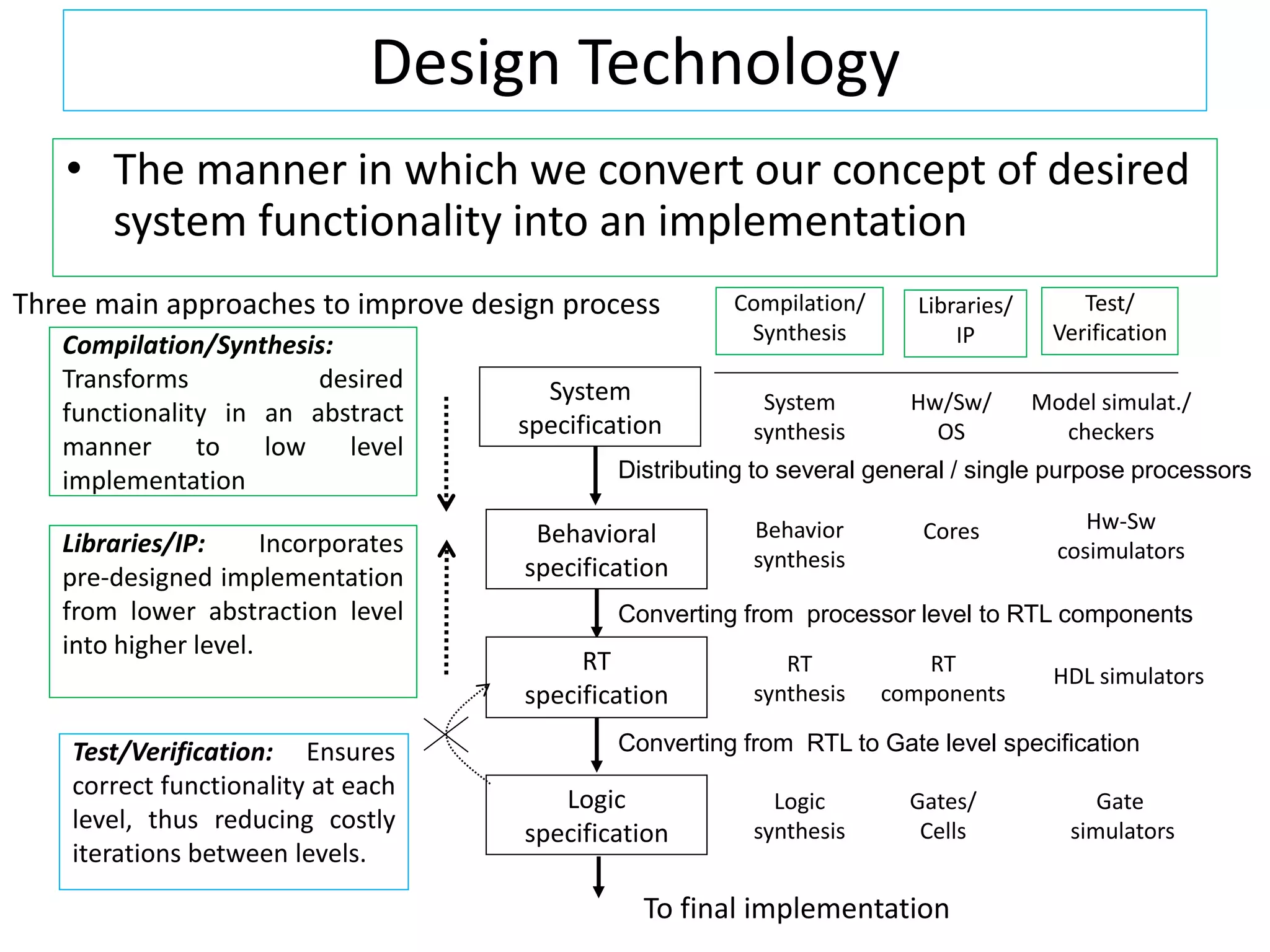
Design Technology
• Themanner in which we convert our concept of desired
system functionality into an implementation
Libraries/IP: Incorporates
pre-designed implementation
from lower abstraction level
into higher level.
System
specification
Behavioral
specification
RT
specification
Logic
specification
To final implementation
Compilation/Synthesis:
Transforms desired
functionality in an abstract
manner to low level
implementation
Test/Verification: Ensures
correct functionality at each
level, thus reducing costly
iterations between levels.
Compilation/
Synthesis
Libraries/
IP
Test/
Verification
System
synthesis
Behavior
synthesis
RT
synthesis
Logic
synthesis
Hw/Sw/
OS
Cores
RT
components
Gates/
Cells
Model simulat./
checkers
Hw-Sw
cosimulators
HDL simulators
Gate
simulators
Distributing to several general / single purpose processors
Converting from processor level to RTL components
Converting from RTL to Gate level specification
Three main approaches to improve design process
133.
Compilation Synthesis
• Abehavioral synthesis (High-level Synthesis) tool
converts a sequential program (C / C++) into finite
state machines (FSM) and register transfers
• A Register transfer (RT) synthesis tool converts Finite
state machines and register transfers into a datapath
of RT components and a controller of Boolean
equations
• Logic Synthesis tool converts Boolean expressions
into a connection of logic gates, called a netlist
134.
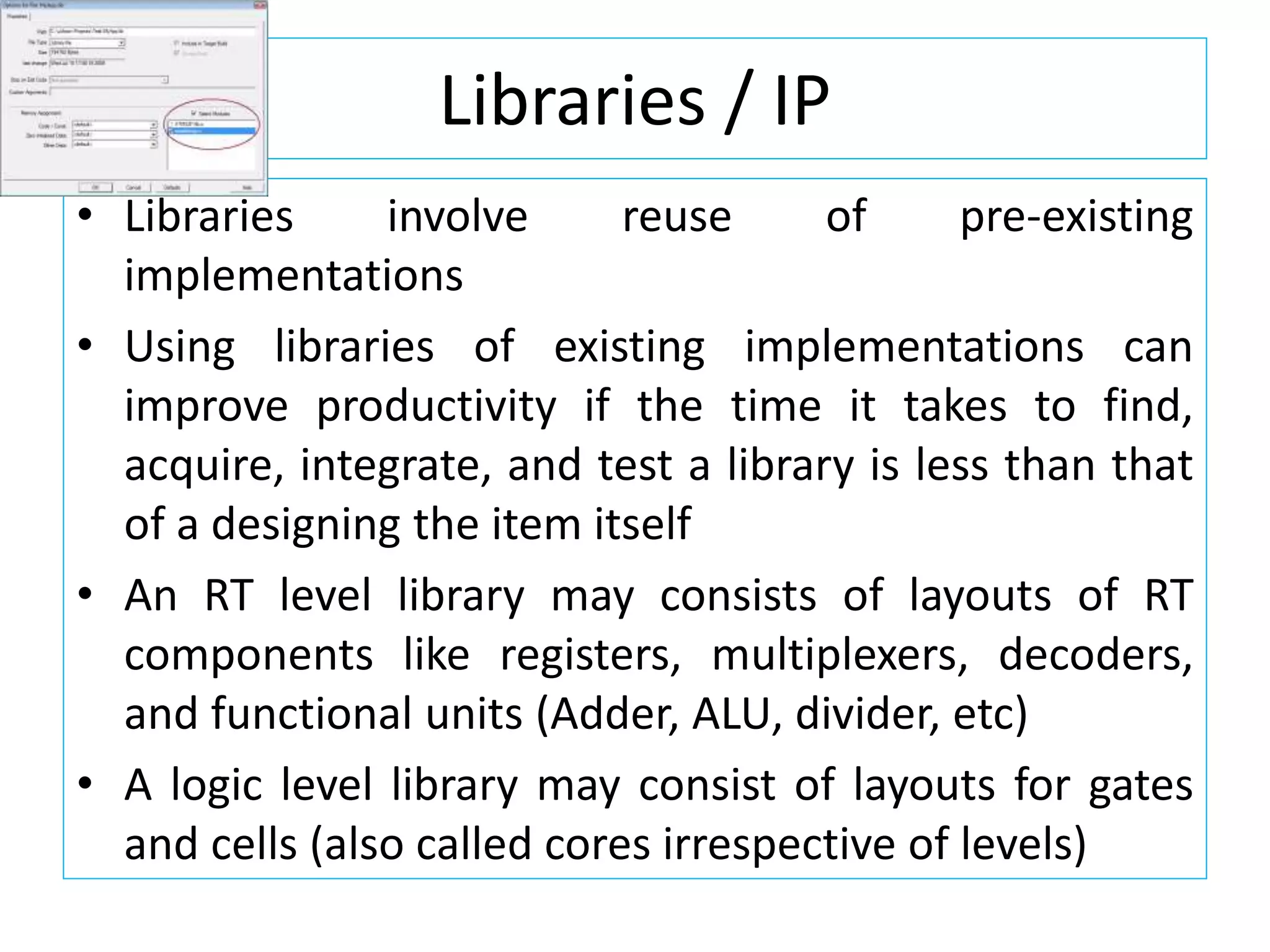
Libraries / IP
•Libraries involve reuse of pre-existing
implementations
• Using libraries of existing implementations can
improve productivity if the time it takes to find,
acquire, integrate, and test a library is less than that
of a designing the item itself
• An RT level library may consists of layouts of RT
components like registers, multiplexers, decoders,
and functional units (Adder, ALU, divider, etc)
• A logic level library may consist of layouts for gates
and cells (also called cores irrespective of levels)
135.
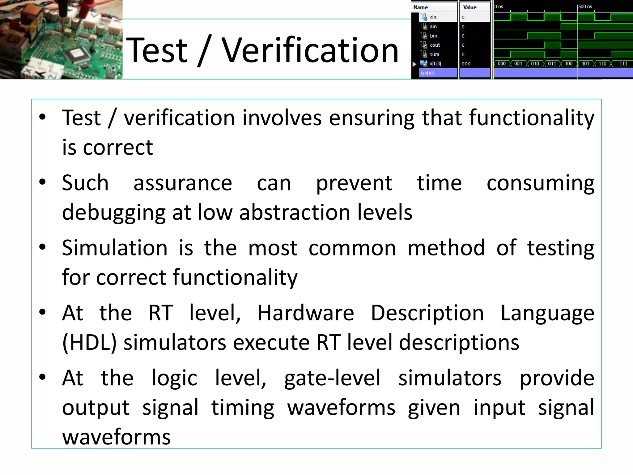
Test / Verification
•Test / verification involves ensuring that functionality
is correct
• Such assurance can prevent time consuming
debugging at low abstraction levels
• Simulation is the most common method of testing
for correct functionality
• At the RT level, Hardware Description Language
(HDL) simulators execute RT level descriptions
• At the logic level, gate-level simulators provide
output signal timing waveforms given input signal
waveforms


![Processor technology
• Processors vary in their customization for the problem at hand
• Example: Summing of the items in an array
total = 0
for i = 1 to N loop
total += M[i]
end loop
General-purpose
processor
Single-purpose
processor
(ASIC)
Application-specific
Instruction set (ASIP)
processor
Desired
functionality](https://image.slidesharecdn.com/unit1-introduction-230124163742-354d7518/75/Unit-1-Introduction-121-2048.jpg)