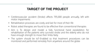
EXOSKELETON ARM
Project Phase II
› PROJECT GUIDE
› Mr. Anuroop PV
› Assistant Professor
› Division of EEE
› GROUP MEMBERS
› Adheena Joseph [19170200]
› Akarsh B Dhanesh [19170204]
› Anagha Chand P [19170207]
› Vivek C [19170240]
1
TARGET OF THE PROJECT
• Cerebrovascular accident (Stroke) affects 795,000 people annually, left with
motor impairments
• Rehabilitation processes are costly and last for most of their life
• Robot aided therapies are found to be effective than conventional therapies
• Aim is To design and model a fully functional hand exoskeleton for
rehabilitation of the patients who survived stroke and the elderly who do not
have enough strength to move their limbs feely
• The system should be IoT-Enabled so that treatment procedures can be
monitored and performed remotely from anywhere around the globe
2
Modus Operandi Followed
1. Deciding the degrees of freedom to be offered
• The proposed exoskeleton arm has 2 degrees of freedom which consist of
flexion/extension for elbow and fingers
2. Calculation of torque required
• Torque required to move elbow joint is much higher than that is required for moving
finger joints
3. Selection of actuators as per requirement
4. Control action setup
• Describes the methods in which the exoskeleton setup can be controlled/commanded
3
5. Design of basic layout of the system
• Includes block diagram representation of whole setup
6. Software Modelling of frame
7. Testing of electronic components
• Includes test results, behavior and characteristics of different components used in this
system
8. 3-D printing of frame
9. Wiring up electronic components
10. Developing software for microcontrollers
• Includes IoT platform setup
11. Test and developments
4
Other experiments include;
• Adding position controller for geared motor
• Discusses about relationship of resistance of potentiometer with shaft angle
• Includes results and tabulation of potentiometer position controller
• Test results of EMG sensor on different individuals
• Plot of Raw EMG output data is included
5
SYSTEM DESIGN
TORQUE CALCULATIONS
𝑊𝑒𝑖𝑔ℎ𝑡 𝑎𝑛𝑑 𝑇𝑜𝑟𝑞𝑢𝑒 𝑟𝑒𝑞𝑢𝑖𝑟𝑒𝑑 𝑓𝑜𝑟 𝑎 𝑏𝑜𝑑𝑦 𝑜𝑓 𝑤𝑒𝑖𝑔ℎ𝑡 65 𝐾𝑔 (𝐴𝑣𝑒𝑟𝑎𝑔𝑒)
𝐴𝑣𝑒𝑟𝑎𝑔𝑒 𝑊𝑒𝑖𝑔ℎ𝑡 𝑜𝑓 𝐹𝑜𝑟𝑒𝑎𝑟𝑚 = 1.75% 𝑜𝑓 65 𝑘𝑔 = 1.1375𝑘𝑔
𝐴𝑑𝑑𝑖𝑡𝑖𝑜𝑛𝑎𝑙 𝑤𝑒𝑖𝑔ℎ𝑡 𝑡ℎ𝑎𝑡 𝑐𝑎𝑛 𝑏𝑒 𝑙𝑖𝑓𝑡𝑒𝑑 = 1𝑘𝑔
𝑇𝑜𝑡𝑎𝑙 𝑊𝑒𝑖𝑔ℎ𝑡 = 1.1375𝑘𝑔 + 1𝑘𝑔 = 2.137𝑘𝑔
𝑇𝑜𝑟𝑞𝑢𝑒 = 𝑊𝑒𝑖𝑔ℎ𝑡(𝑤) 𝑥 𝐿𝑒𝑛𝑔𝑡ℎ(𝑙)
𝑇𝑜𝑟𝑞𝑢𝑒 = 2.137 𝑥20 = 42.74 𝑘𝑔. 𝑐𝑚
𝑇ℎ𝑒𝑟𝑒𝑓𝑜𝑟𝑒, 𝑟𝑒𝑞𝑢𝑖𝑟𝑒𝑑 𝑡𝑜𝑟𝑞𝑢𝑒 = 42.74 𝑘𝑔. 𝑐𝑚
6
SELECTION OF ACTUATORS
• The required amount of torque is around 50 𝑘𝑔. 𝑐𝑚 in elbow joint.
• In this project metallic worm gear motor having maximum torque of
60 𝑘𝑔. 𝑐𝑚 is used.
• The voltage rating of this motor is 12V.
• For flexion and relaxation of fingers the required torque is 1.5 𝑘𝑔. 𝑐𝑚.
• Micro servo motor with rated voltage 5V DC and a rated torque of
1.8 𝑘𝑔. 𝑐𝑚 is used.
7
BLOCK DIAGRAM REPRESENTATION
8
S1
MICROCONTROLLER
• Arduino uno is used in this project
as a local controller due to its
compatibility for wide range of
devices
• NodeMCU is also another type of
microcontroller used in the system
for enabling IoT functionality
• Arduino Uno receives data from
NodeMCU and EMG sensors and
send signals to the actuators
through motor driver.
9
• Out of its 6 analog input pins, A4 is
used for receiving data from EMG
sensors & A5 is used to connect
potentiometer
• Digital pins 0&1 (Tx & Rx) And
analog pin A0 are used for serial
communication between Arduino &
NodeMCU
• Digital o/p pins 5&6 are connected
to input channel A of motor driver
Microcontroller
ATmega328P – 8-bit
AVR family
microcontroller
Input Voltage
Limits
6-20V
Analog Input Pins 6 (A0 – A5)
Digital I/O Pins
14 (Out of which 6
provide PWM output)
DC Current on I/O
Pins
40 mA
10
• The controller that is used for
enabling IoT functionalities in this
project is NodeMCU
• One can enable or disable the
digital output pins and put any
value as output to the analogue
output pins in this board wirelessly
by accessing the Ip-address of the
specific pin on manufacturers
server
• The output voltage is only 3.3 v
making it difficult to interface with
common devices which uses 5v
11
MOTOR DRIVER
• Output voltage of microcontroller is
not sufficient for driving heavy
motors
• Motor driver act as an interface
between Arduino and the motors
• It works on the concept of H-bridge
• L298 N consist of two H-bridge
• H-bridge is a circuit which allows
the voltage to be flown in either
direction
12
H - Bridge
• H-bridge is a simple circuit, containing four switching
elements, with the load at the center, in an H-like
configuration
• The switching elements (Q1 to Q4) are usually bi-
polar or FET transistors
• The top-end of the bridge is connected to a power
supply (12V) and the bottom-end is grounded.
• if Q1 and Q4 are turned on, the left lead of the motor
will be connected to the power supply, while the right
lead is connected to ground
• Current starts flowing through the motor which
energizes the motor in (let’s say) the forward direction
13
EMG SENSOR
• EMG sensor is used in this project
to pick up signals produced by
motor neurons when muscles are
flexed/relaxed
• EMG sensor modules, which can be
easily interfaced with Arduino or
any other development boards are
used
14
ACTUATORS
• There are two different type of actuators used in this project.
• One with maximum torque capacity of 60 𝑘𝑔. 𝑐𝑚 and another servo
motor with a torque capacity of 1.8 𝑘𝑔. 𝑐𝑚
• For lifting and lowering the elbow joint, a worm gear motor is used.
• For the movement of figures. Micro servo motors are used
• Tower pro micro servo motors are tiny and lightweight with high
output power.
• This motor can be directly connected to Arduino UNO
15
• There are mainly two parts for worm gear
motor
• Worm gear - consists of a shaft with threading that
spiral itself on the shaft.
• DC Motor - The motor shaft is attached to the worm
gear.
• A worm drive can reduce rotational speed and
transmit high torque.
• It can transfer motion in 90 degrees.
• Both sliding and rolling action of the worm and
gear come into play during the meshing of the
gears.
• Position control of these motors requires
additional mechanism
16
POSITION SENSOR (POTENTIOMETER)
• It is the most commonly used position sensor.
• It has a wiper contact linked to a mechanical shaft that is
angular (rotational) in its movement
• It causes the resistance value between the wiper/slider
and the two end connections to change, giving an
electrical signal output
• The actual wiper position on the resistive track and its
resistance value are proportional
• The shaft of potentiometer is coupled with shaft of
worm gear motor
• The voltage across the viper contact and either of other
terminal is proportional to shaft angle as observed
17
HARDWARE MODELLING
DESIGNING 3-D MODEL OF THE FRAME
• The basic design of the frame was designed using AutoCAD 2017
• Several types of 3D modelling are available in AutoCAD
• Each of these 3D modelling technologies offer a different set of capabilities.
Various Visual styles of same object
18
• Wireframe and 3-d solid modelling simultaneously are used to model the
frame of the system
• A wireframe model is a skeletal description of a 3D object.
• There are no surfaces in a wireframe model; it consists only of points, lines,
and curves that describe the edges of the object
• Using a wire-frame model allows for the visualization of the underlying
design structure of a 3D model
• Wireframe model allows us to calculate the area and infill of the total
structure
• By knowing these, amount of material to print the model can be calculated
19
• Solids are created in AutoCAD by
initially drawing a 2d shape
similar to plan of buildings
• And these shapes are used to
create 3d objects just by pulling
them upwards (Extrude/Prespull)
• Different tools are available for
different actions like Trim, Extend,
Rotate, Scale, Offset etc.
20
RESULTS OF MODELLING
21
S2
3-D PRINTING THE MODELS
• The designed models of the frame was exported into “.stl” file which is a
standard format for 3-D models
• 3d printer (Prusa I3 mk3) is used to print the models using PLA Filament
• This type of printer is an FDM (Fused Deposition Modelling) printer
• An FDM Printer consists of:
• Controller Board
• Filament
• Frame
• Motion Components
• Power Supply Unit
• Print Bed
• Print Head (Extruder)
22
• For 3d printing, the designed in
stereolithographic (.stl) format should
be converted into g-code for 3d
printing
• G-code is a programming language for
CNC that instructs machines where and
how to move
• .stl format is converted to G-code
using Slicer software
23
• G1 is the command used for linear
movement
• G1 X0 Y0 F2400 ; move to the X=0 Y=0
position on the bed at a speed of 2400
mm/min
• M104 and M109 – Extruder Heating
Commands
• G10 and G11 – Retract and Unretract
• M104: Set Extruder Temperature
• M104 S190 ; set extruder temperature at
190°
• M112: Emergency Stop
24
TESTING OF MANUAL G-CODE
FOR A SQUARE
• M109 S240 ; set head and wait to arrive at 240° C
• G21 ; set system to millimeter (10 mean 10mm)
• G91 ; set to incremental ( any x10 mean move 10mm on
axis x)
• M83 ; Set extruder to incremental (any E10 mean 10mm
wire on extruder)
• G28 ; Go home all axes (X,Y,Z)
• G1 X10 Y10 ; Go to coordinate 10,10 without wire
• ;Make a square 30x30mm with 1mm/cm wire ( E3
represents 3cm )
• G1 X30 Y0 E3
• G1 X0 Y30 E3
• G1 X-30 Y0 E3
• G1 X0 Y-30 E3
• Z0.2 ; rise with 0.2mm
• (Repeat for 10 times)
25
Video
TESTING EMG SENSORS
• EMG sensor is used in this project to pick
up signals produced by motor neurons
when muscles are flexed/relaxed
• EMG sensor modules, which can be easily
interfaced with Arduino or any other
development boards are used for testing
the sensor
• A basic analogue read program is used to
test the signals produced by EMG sensors
• Sensor output is connected to A0 pin of
Arduino
• Serial monitor and serial plotter are used
to tabulate the data.
26
WIRING UP THE CIRCUIT
27
• The system uses mainly 2 types of microcontroller, Arduino uno &
NodeMCU(esp8266)
• Esp8266 is used in this project to enable IoT functionality
• Arduino acts as local controller for the arm, it drives the actuators in both the
ankle joint and fingers
• EMG Sensors are connected to the analogue input pin of Arduino board
• High torque metallic geared motor is interfaced with Arduino using a motor
driver
• For controlling the angular rotation of this motor, a potentiometer is used
28
CONTROL FOR DC WORM GEAR MOTOR
• DC Motors can be made to turn either clockwise or counter-clockwise by
changing the polarity of the voltage applied to their terminals
• Stopping or reversing the motor can only be achieved by cutting off electric
supply or reversing polarity
• In order to control the shaft position of a DC motor shaft position should be
encoded
• This ‘current position’ will be compared against an ‘desired position’ and a
‘positional error’ will be generated
29
Idea of the setup
• The basic idea behind converting a
DC motor to servo is to find the
position of the shaft and apply a
DC voltage to get the Shaft to the
expected position.
• The whole controller is modelled as
an Arduino program
30
Library for Custom Servo
• Arduino code to control angle of a
motor shaft using a potentiometer
for feedback is given
• To do so, Shaft of potentiometer is
mechanically coupled with shaft of
the geared motor
• Body of potentiometer is rigidly
fixed
• When shaft rotates, potentiometer
gives a value from around 0-1023
31
One can rotate motor to particular angle using command; customServo.GoToAngle(i);
32
S3
FINGER MOTION CONTROL
• Fingers are controlled using
Bowden cables attached to a
glove-like support for fingers
• Each cable is connected to a servo
motor
• When the servo motor is rotated, it
causes the inner cable in the
Bowden cable gets pulled and
fingers are flexed
• The finger returns to the relaxed
position as the servo rotates in the
other direction
33
SETTING UP IoT FUNCTIONALITY
• The exoskeleton can be controlled using
voice commands said to google
assistant in one’s smartphone.
• For doing that the google assistant and
the microcontroller used in this project
must be bridged
• In this project we made use of
WEBHOOKS on IFTTT to handle a web
service , which is BLYNK
• For setting up google assistant control,
first blynk application must be
configured with the Esp8266 board
34
• After setting up Blynk application We
shall use IFTTT to make a chain
between Google assistant and Blynk.
• Once the commands are given, one
has to select “that” function in IFTTT &
select WEBHOOKS
• The ip address of the pin whose output
needs to be altered must be given in a
particular format.
• “http://IP of blynk-cloud/auth
id/update/<digital pin> “
• Where auth id is blynk authorization id
• Digital pin is GPIO pin mapped to
Esp8266
35
PUT
CODING THE WHOLE SETUP
Code For NodeMCU 36Code For Arduino
RESULTS OF EXPERIMENTS CONDUCTED
TEST RESULTS OF EMG SENSOR
Muscles Flexed Muscles Relaxed
It is found that voltage
output of EMG Sensor
increases with increase
in muscle activity
37
CUSTOM SERVO MOTOR
Angle of motor shaft
Value obtained on serial
monitor
10 314
20 354
30 396
40 435
50 478
60 520
70 558
80 597
90 636
100 676
Shaft angle Vs Pot Output Graphical Representation
38
TEST RESULTS OF MANUAL
G-CODE RUN
• Tevo tarantula Pro 3-D printer was
used to test the G-code for printing
a square of dimensions 30x30x2mm
• Test results are shown in figure
39
FINAL MODEL
40
CONCLUSION AND FUTURE SCOPES
• The 2-DOF robotic exoskeleton arm was designed and built which can be utilized
for rehabilitation and training purposes
• The arm can rotate over the range of -90 to +50 degrees for elbow joint
• The system helps physiotherapists to wirelessly communicate with the exoskeleton
and thereby perform therapy procedures without actually visiting the patient
• Electromyographic signals are used to assist the patient in lifting & lowering of their
arm
• A wide range of voice commands that can be personalized makes the system easier
to use
• Any necessary additional features can be introduced by a simple software update
• Wearable robots and exoskeletons assist in lifting weight for workers and are
generally utilized for engineering and logistical purposes
• Militaries across the world are certainly interested in designing weaponized exo-suits
for their armies of the future
41
S4
Thank You
42

Exoskeleton arm ppt

  • 1.
    EXOSKELETON ARM Project PhaseII › PROJECT GUIDE › Mr. Anuroop PV › Assistant Professor › Division of EEE › GROUP MEMBERS › Adheena Joseph [19170200] › Akarsh B Dhanesh [19170204] › Anagha Chand P [19170207] › Vivek C [19170240] 1
  • 2.
    TARGET OF THEPROJECT • Cerebrovascular accident (Stroke) affects 795,000 people annually, left with motor impairments • Rehabilitation processes are costly and last for most of their life • Robot aided therapies are found to be effective than conventional therapies • Aim is To design and model a fully functional hand exoskeleton for rehabilitation of the patients who survived stroke and the elderly who do not have enough strength to move their limbs feely • The system should be IoT-Enabled so that treatment procedures can be monitored and performed remotely from anywhere around the globe 2
  • 3.
    Modus Operandi Followed 1.Deciding the degrees of freedom to be offered • The proposed exoskeleton arm has 2 degrees of freedom which consist of flexion/extension for elbow and fingers 2. Calculation of torque required • Torque required to move elbow joint is much higher than that is required for moving finger joints 3. Selection of actuators as per requirement 4. Control action setup • Describes the methods in which the exoskeleton setup can be controlled/commanded 3
  • 4.
    5. Design ofbasic layout of the system • Includes block diagram representation of whole setup 6. Software Modelling of frame 7. Testing of electronic components • Includes test results, behavior and characteristics of different components used in this system 8. 3-D printing of frame 9. Wiring up electronic components 10. Developing software for microcontrollers • Includes IoT platform setup 11. Test and developments 4
  • 5.
    Other experiments include; •Adding position controller for geared motor • Discusses about relationship of resistance of potentiometer with shaft angle • Includes results and tabulation of potentiometer position controller • Test results of EMG sensor on different individuals • Plot of Raw EMG output data is included 5
  • 6.
    SYSTEM DESIGN TORQUE CALCULATIONS 𝑊𝑒𝑖𝑔ℎ𝑡𝑎𝑛𝑑 𝑇𝑜𝑟𝑞𝑢𝑒 𝑟𝑒𝑞𝑢𝑖𝑟𝑒𝑑 𝑓𝑜𝑟 𝑎 𝑏𝑜𝑑𝑦 𝑜𝑓 𝑤𝑒𝑖𝑔ℎ𝑡 65 𝐾𝑔 (𝐴𝑣𝑒𝑟𝑎𝑔𝑒) 𝐴𝑣𝑒𝑟𝑎𝑔𝑒 𝑊𝑒𝑖𝑔ℎ𝑡 𝑜𝑓 𝐹𝑜𝑟𝑒𝑎𝑟𝑚 = 1.75% 𝑜𝑓 65 𝑘𝑔 = 1.1375𝑘𝑔 𝐴𝑑𝑑𝑖𝑡𝑖𝑜𝑛𝑎𝑙 𝑤𝑒𝑖𝑔ℎ𝑡 𝑡ℎ𝑎𝑡 𝑐𝑎𝑛 𝑏𝑒 𝑙𝑖𝑓𝑡𝑒𝑑 = 1𝑘𝑔 𝑇𝑜𝑡𝑎𝑙 𝑊𝑒𝑖𝑔ℎ𝑡 = 1.1375𝑘𝑔 + 1𝑘𝑔 = 2.137𝑘𝑔 𝑇𝑜𝑟𝑞𝑢𝑒 = 𝑊𝑒𝑖𝑔ℎ𝑡(𝑤) 𝑥 𝐿𝑒𝑛𝑔𝑡ℎ(𝑙) 𝑇𝑜𝑟𝑞𝑢𝑒 = 2.137 𝑥20 = 42.74 𝑘𝑔. 𝑐𝑚 𝑇ℎ𝑒𝑟𝑒𝑓𝑜𝑟𝑒, 𝑟𝑒𝑞𝑢𝑖𝑟𝑒𝑑 𝑡𝑜𝑟𝑞𝑢𝑒 = 42.74 𝑘𝑔. 𝑐𝑚 6
  • 7.
    SELECTION OF ACTUATORS •The required amount of torque is around 50 𝑘𝑔. 𝑐𝑚 in elbow joint. • In this project metallic worm gear motor having maximum torque of 60 𝑘𝑔. 𝑐𝑚 is used. • The voltage rating of this motor is 12V. • For flexion and relaxation of fingers the required torque is 1.5 𝑘𝑔. 𝑐𝑚. • Micro servo motor with rated voltage 5V DC and a rated torque of 1.8 𝑘𝑔. 𝑐𝑚 is used. 7
  • 8.
  • 9.
    MICROCONTROLLER • Arduino unois used in this project as a local controller due to its compatibility for wide range of devices • NodeMCU is also another type of microcontroller used in the system for enabling IoT functionality • Arduino Uno receives data from NodeMCU and EMG sensors and send signals to the actuators through motor driver. 9
  • 10.
    • Out ofits 6 analog input pins, A4 is used for receiving data from EMG sensors & A5 is used to connect potentiometer • Digital pins 0&1 (Tx & Rx) And analog pin A0 are used for serial communication between Arduino & NodeMCU • Digital o/p pins 5&6 are connected to input channel A of motor driver Microcontroller ATmega328P – 8-bit AVR family microcontroller Input Voltage Limits 6-20V Analog Input Pins 6 (A0 – A5) Digital I/O Pins 14 (Out of which 6 provide PWM output) DC Current on I/O Pins 40 mA 10
  • 11.
    • The controllerthat is used for enabling IoT functionalities in this project is NodeMCU • One can enable or disable the digital output pins and put any value as output to the analogue output pins in this board wirelessly by accessing the Ip-address of the specific pin on manufacturers server • The output voltage is only 3.3 v making it difficult to interface with common devices which uses 5v 11
  • 12.
    MOTOR DRIVER • Outputvoltage of microcontroller is not sufficient for driving heavy motors • Motor driver act as an interface between Arduino and the motors • It works on the concept of H-bridge • L298 N consist of two H-bridge • H-bridge is a circuit which allows the voltage to be flown in either direction 12
  • 13.
    H - Bridge •H-bridge is a simple circuit, containing four switching elements, with the load at the center, in an H-like configuration • The switching elements (Q1 to Q4) are usually bi- polar or FET transistors • The top-end of the bridge is connected to a power supply (12V) and the bottom-end is grounded. • if Q1 and Q4 are turned on, the left lead of the motor will be connected to the power supply, while the right lead is connected to ground • Current starts flowing through the motor which energizes the motor in (let’s say) the forward direction 13
  • 14.
    EMG SENSOR • EMGsensor is used in this project to pick up signals produced by motor neurons when muscles are flexed/relaxed • EMG sensor modules, which can be easily interfaced with Arduino or any other development boards are used 14
  • 15.
    ACTUATORS • There aretwo different type of actuators used in this project. • One with maximum torque capacity of 60 𝑘𝑔. 𝑐𝑚 and another servo motor with a torque capacity of 1.8 𝑘𝑔. 𝑐𝑚 • For lifting and lowering the elbow joint, a worm gear motor is used. • For the movement of figures. Micro servo motors are used • Tower pro micro servo motors are tiny and lightweight with high output power. • This motor can be directly connected to Arduino UNO 15
  • 16.
    • There aremainly two parts for worm gear motor • Worm gear - consists of a shaft with threading that spiral itself on the shaft. • DC Motor - The motor shaft is attached to the worm gear. • A worm drive can reduce rotational speed and transmit high torque. • It can transfer motion in 90 degrees. • Both sliding and rolling action of the worm and gear come into play during the meshing of the gears. • Position control of these motors requires additional mechanism 16
  • 17.
    POSITION SENSOR (POTENTIOMETER) •It is the most commonly used position sensor. • It has a wiper contact linked to a mechanical shaft that is angular (rotational) in its movement • It causes the resistance value between the wiper/slider and the two end connections to change, giving an electrical signal output • The actual wiper position on the resistive track and its resistance value are proportional • The shaft of potentiometer is coupled with shaft of worm gear motor • The voltage across the viper contact and either of other terminal is proportional to shaft angle as observed 17
  • 18.
    HARDWARE MODELLING DESIGNING 3-DMODEL OF THE FRAME • The basic design of the frame was designed using AutoCAD 2017 • Several types of 3D modelling are available in AutoCAD • Each of these 3D modelling technologies offer a different set of capabilities. Various Visual styles of same object 18
  • 19.
    • Wireframe and3-d solid modelling simultaneously are used to model the frame of the system • A wireframe model is a skeletal description of a 3D object. • There are no surfaces in a wireframe model; it consists only of points, lines, and curves that describe the edges of the object • Using a wire-frame model allows for the visualization of the underlying design structure of a 3D model • Wireframe model allows us to calculate the area and infill of the total structure • By knowing these, amount of material to print the model can be calculated 19
  • 20.
    • Solids arecreated in AutoCAD by initially drawing a 2d shape similar to plan of buildings • And these shapes are used to create 3d objects just by pulling them upwards (Extrude/Prespull) • Different tools are available for different actions like Trim, Extend, Rotate, Scale, Offset etc. 20
  • 21.
  • 22.
    3-D PRINTING THEMODELS • The designed models of the frame was exported into “.stl” file which is a standard format for 3-D models • 3d printer (Prusa I3 mk3) is used to print the models using PLA Filament • This type of printer is an FDM (Fused Deposition Modelling) printer • An FDM Printer consists of: • Controller Board • Filament • Frame • Motion Components • Power Supply Unit • Print Bed • Print Head (Extruder) 22
  • 23.
    • For 3dprinting, the designed in stereolithographic (.stl) format should be converted into g-code for 3d printing • G-code is a programming language for CNC that instructs machines where and how to move • .stl format is converted to G-code using Slicer software 23
  • 24.
    • G1 isthe command used for linear movement • G1 X0 Y0 F2400 ; move to the X=0 Y=0 position on the bed at a speed of 2400 mm/min • M104 and M109 – Extruder Heating Commands • G10 and G11 – Retract and Unretract • M104: Set Extruder Temperature • M104 S190 ; set extruder temperature at 190° • M112: Emergency Stop 24
  • 25.
    TESTING OF MANUALG-CODE FOR A SQUARE • M109 S240 ; set head and wait to arrive at 240° C • G21 ; set system to millimeter (10 mean 10mm) • G91 ; set to incremental ( any x10 mean move 10mm on axis x) • M83 ; Set extruder to incremental (any E10 mean 10mm wire on extruder) • G28 ; Go home all axes (X,Y,Z) • G1 X10 Y10 ; Go to coordinate 10,10 without wire • ;Make a square 30x30mm with 1mm/cm wire ( E3 represents 3cm ) • G1 X30 Y0 E3 • G1 X0 Y30 E3 • G1 X-30 Y0 E3 • G1 X0 Y-30 E3 • Z0.2 ; rise with 0.2mm • (Repeat for 10 times) 25 Video
  • 26.
    TESTING EMG SENSORS •EMG sensor is used in this project to pick up signals produced by motor neurons when muscles are flexed/relaxed • EMG sensor modules, which can be easily interfaced with Arduino or any other development boards are used for testing the sensor • A basic analogue read program is used to test the signals produced by EMG sensors • Sensor output is connected to A0 pin of Arduino • Serial monitor and serial plotter are used to tabulate the data. 26
  • 27.
    WIRING UP THECIRCUIT 27
  • 28.
    • The systemuses mainly 2 types of microcontroller, Arduino uno & NodeMCU(esp8266) • Esp8266 is used in this project to enable IoT functionality • Arduino acts as local controller for the arm, it drives the actuators in both the ankle joint and fingers • EMG Sensors are connected to the analogue input pin of Arduino board • High torque metallic geared motor is interfaced with Arduino using a motor driver • For controlling the angular rotation of this motor, a potentiometer is used 28
  • 29.
    CONTROL FOR DCWORM GEAR MOTOR • DC Motors can be made to turn either clockwise or counter-clockwise by changing the polarity of the voltage applied to their terminals • Stopping or reversing the motor can only be achieved by cutting off electric supply or reversing polarity • In order to control the shaft position of a DC motor shaft position should be encoded • This ‘current position’ will be compared against an ‘desired position’ and a ‘positional error’ will be generated 29
  • 30.
    Idea of thesetup • The basic idea behind converting a DC motor to servo is to find the position of the shaft and apply a DC voltage to get the Shaft to the expected position. • The whole controller is modelled as an Arduino program 30
  • 31.
    Library for CustomServo • Arduino code to control angle of a motor shaft using a potentiometer for feedback is given • To do so, Shaft of potentiometer is mechanically coupled with shaft of the geared motor • Body of potentiometer is rigidly fixed • When shaft rotates, potentiometer gives a value from around 0-1023 31
  • 32.
    One can rotatemotor to particular angle using command; customServo.GoToAngle(i); 32 S3
  • 33.
    FINGER MOTION CONTROL •Fingers are controlled using Bowden cables attached to a glove-like support for fingers • Each cable is connected to a servo motor • When the servo motor is rotated, it causes the inner cable in the Bowden cable gets pulled and fingers are flexed • The finger returns to the relaxed position as the servo rotates in the other direction 33
  • 34.
    SETTING UP IoTFUNCTIONALITY • The exoskeleton can be controlled using voice commands said to google assistant in one’s smartphone. • For doing that the google assistant and the microcontroller used in this project must be bridged • In this project we made use of WEBHOOKS on IFTTT to handle a web service , which is BLYNK • For setting up google assistant control, first blynk application must be configured with the Esp8266 board 34
  • 35.
    • After settingup Blynk application We shall use IFTTT to make a chain between Google assistant and Blynk. • Once the commands are given, one has to select “that” function in IFTTT & select WEBHOOKS • The ip address of the pin whose output needs to be altered must be given in a particular format. • “http://IP of blynk-cloud/auth id/update/<digital pin> “ • Where auth id is blynk authorization id • Digital pin is GPIO pin mapped to Esp8266 35 PUT
  • 36.
    CODING THE WHOLESETUP Code For NodeMCU 36Code For Arduino
  • 37.
    RESULTS OF EXPERIMENTSCONDUCTED TEST RESULTS OF EMG SENSOR Muscles Flexed Muscles Relaxed It is found that voltage output of EMG Sensor increases with increase in muscle activity 37
  • 38.
    CUSTOM SERVO MOTOR Angleof motor shaft Value obtained on serial monitor 10 314 20 354 30 396 40 435 50 478 60 520 70 558 80 597 90 636 100 676 Shaft angle Vs Pot Output Graphical Representation 38
  • 39.
    TEST RESULTS OFMANUAL G-CODE RUN • Tevo tarantula Pro 3-D printer was used to test the G-code for printing a square of dimensions 30x30x2mm • Test results are shown in figure 39
  • 40.
  • 41.
    CONCLUSION AND FUTURESCOPES • The 2-DOF robotic exoskeleton arm was designed and built which can be utilized for rehabilitation and training purposes • The arm can rotate over the range of -90 to +50 degrees for elbow joint • The system helps physiotherapists to wirelessly communicate with the exoskeleton and thereby perform therapy procedures without actually visiting the patient • Electromyographic signals are used to assist the patient in lifting & lowering of their arm • A wide range of voice commands that can be personalized makes the system easier to use • Any necessary additional features can be introduced by a simple software update • Wearable robots and exoskeletons assist in lifting weight for workers and are generally utilized for engineering and logistical purposes • Militaries across the world are certainly interested in designing weaponized exo-suits for their armies of the future 41 S4
  • 42.