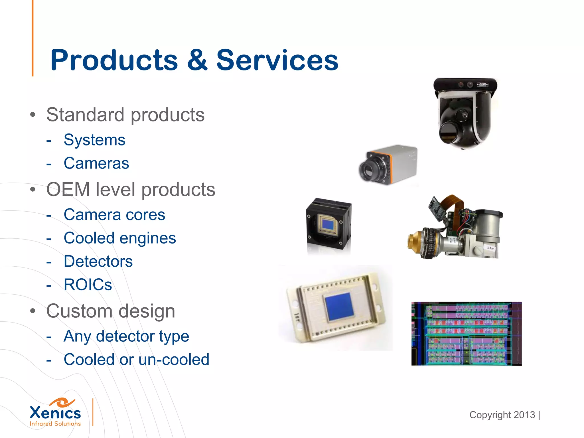
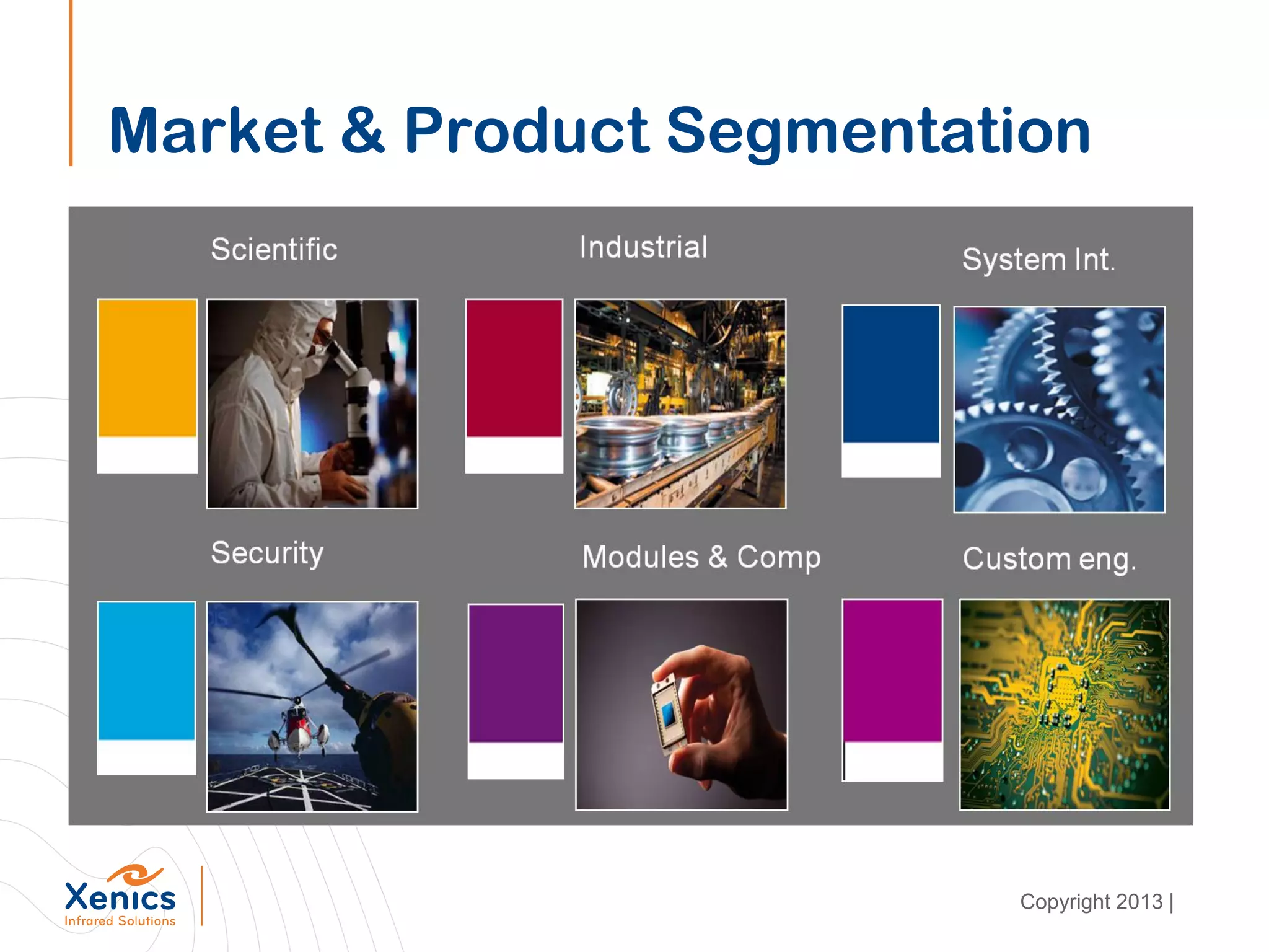
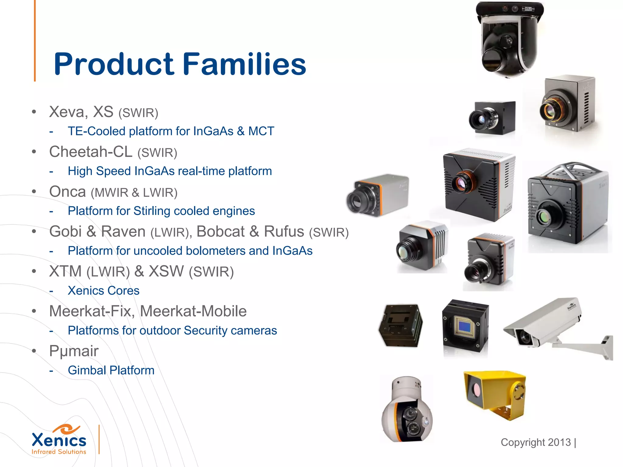
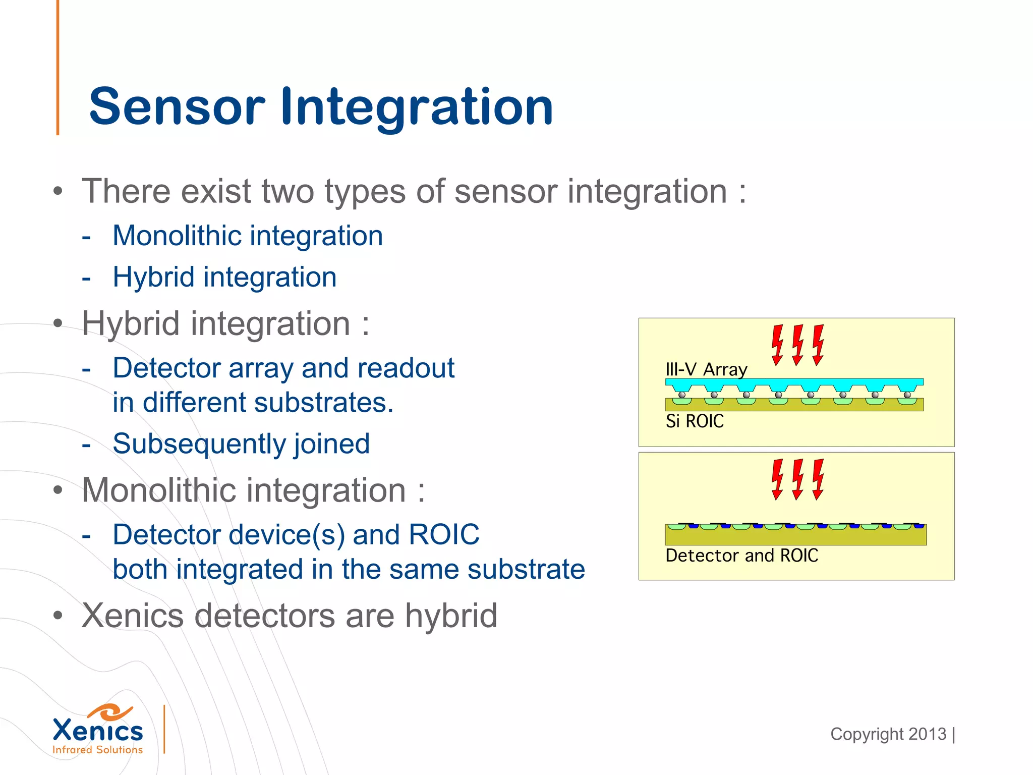
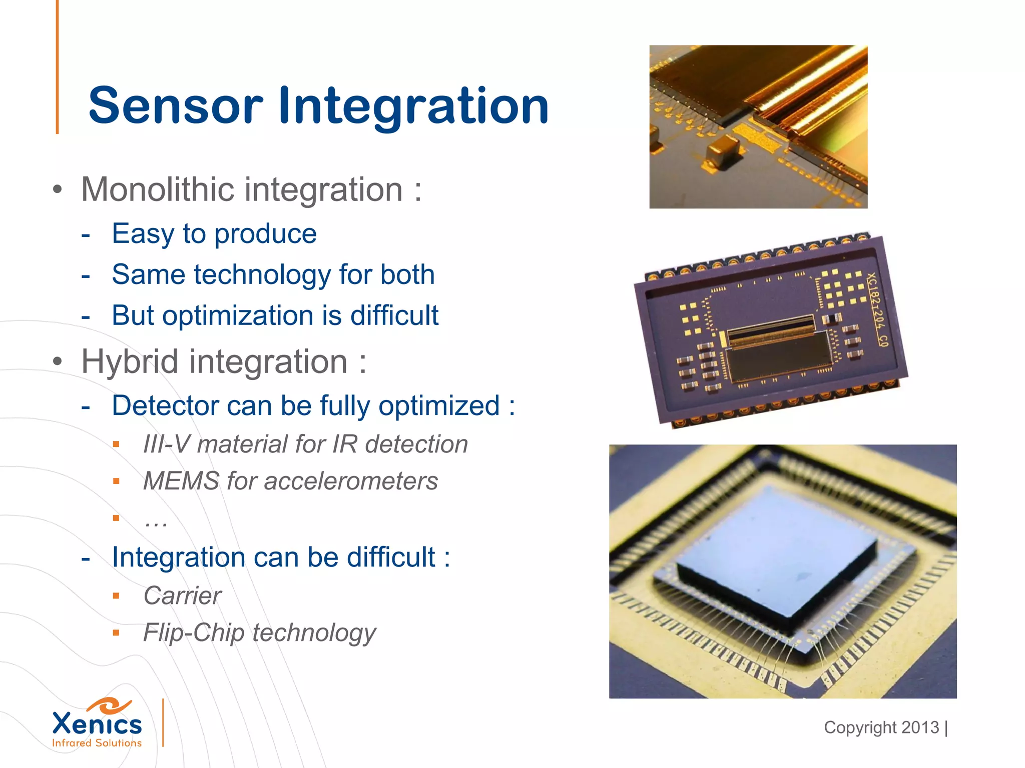
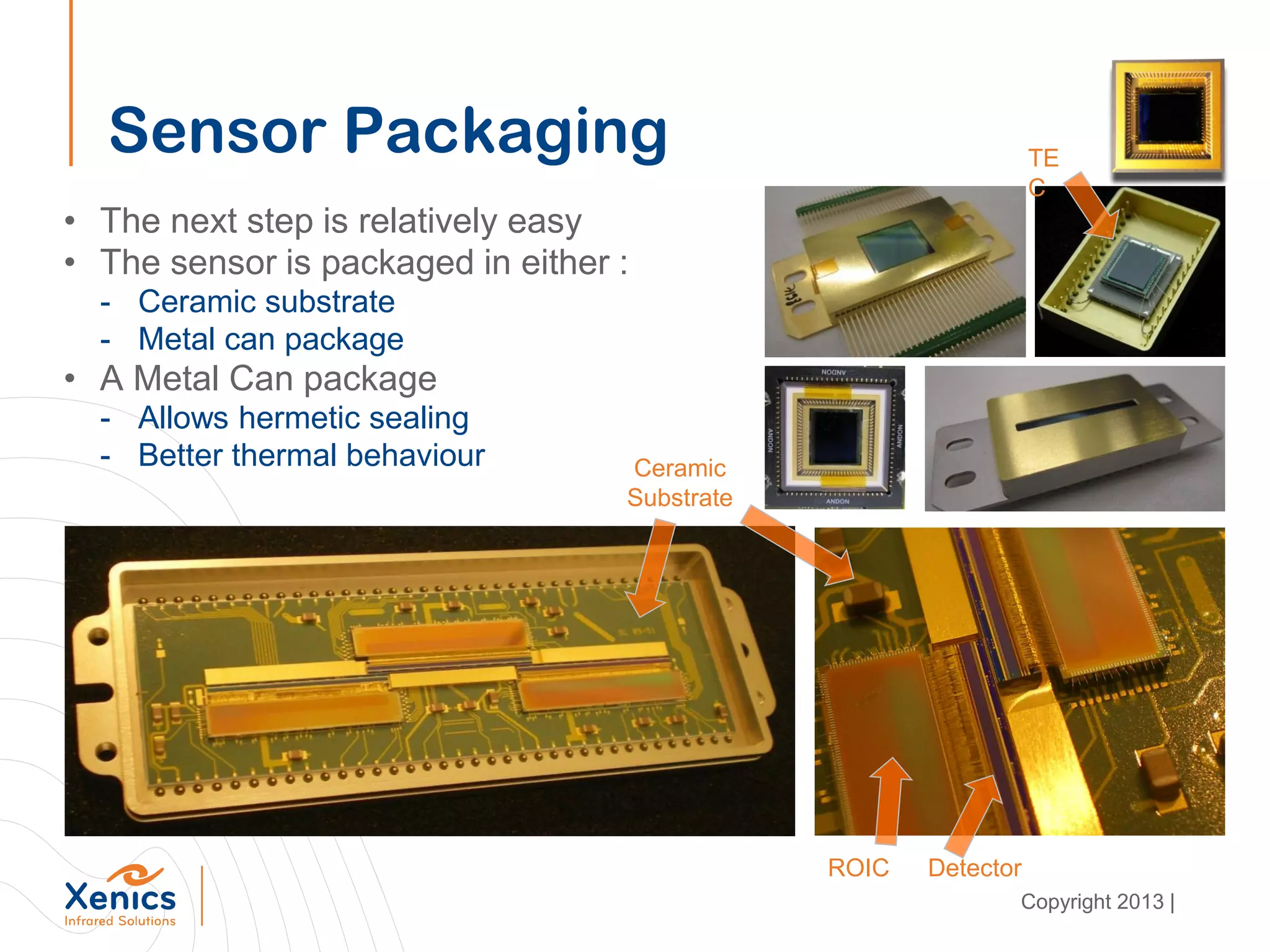
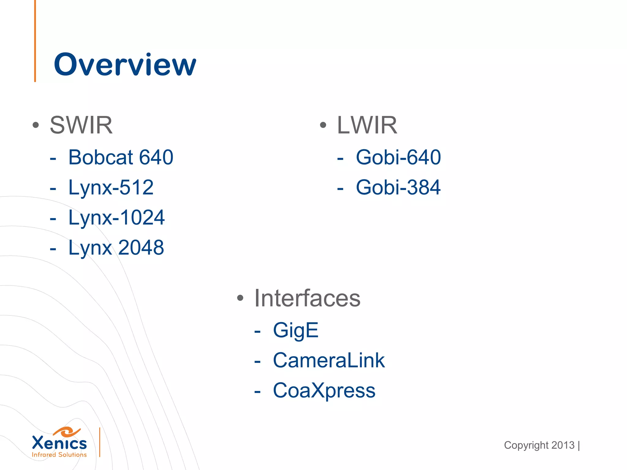
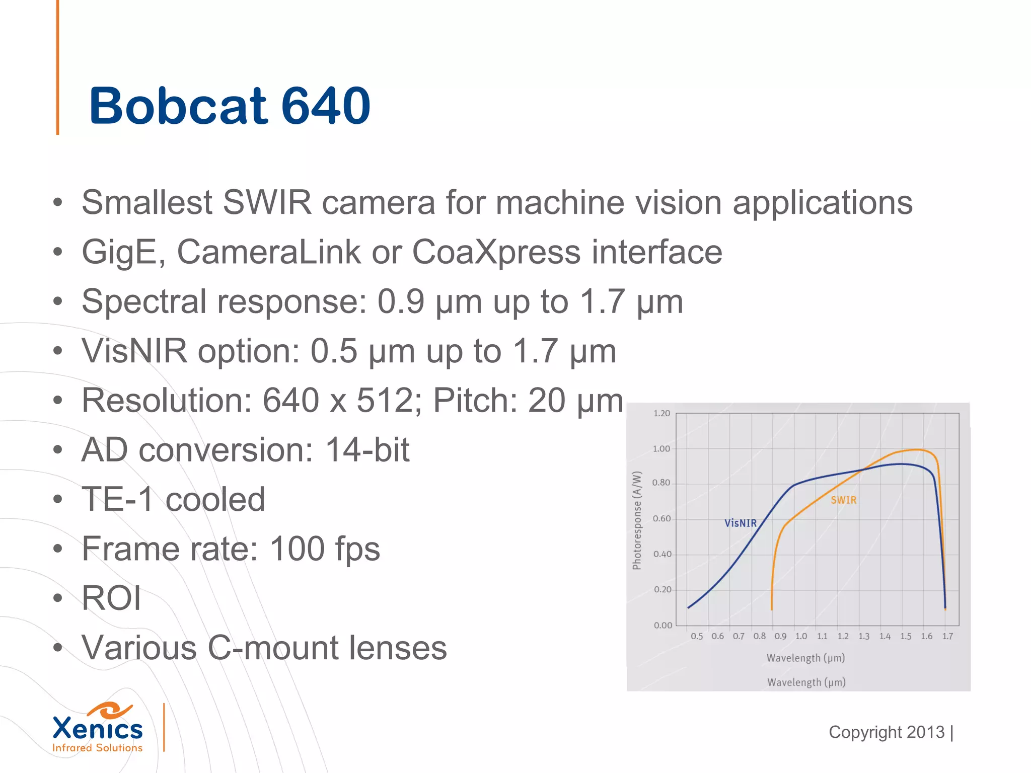
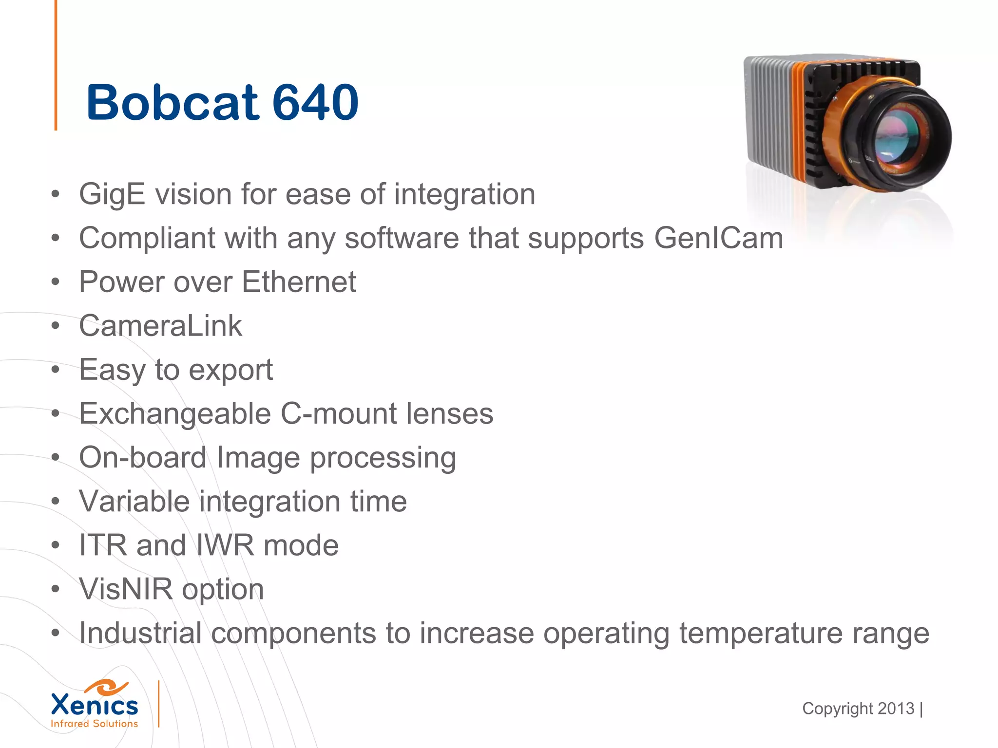
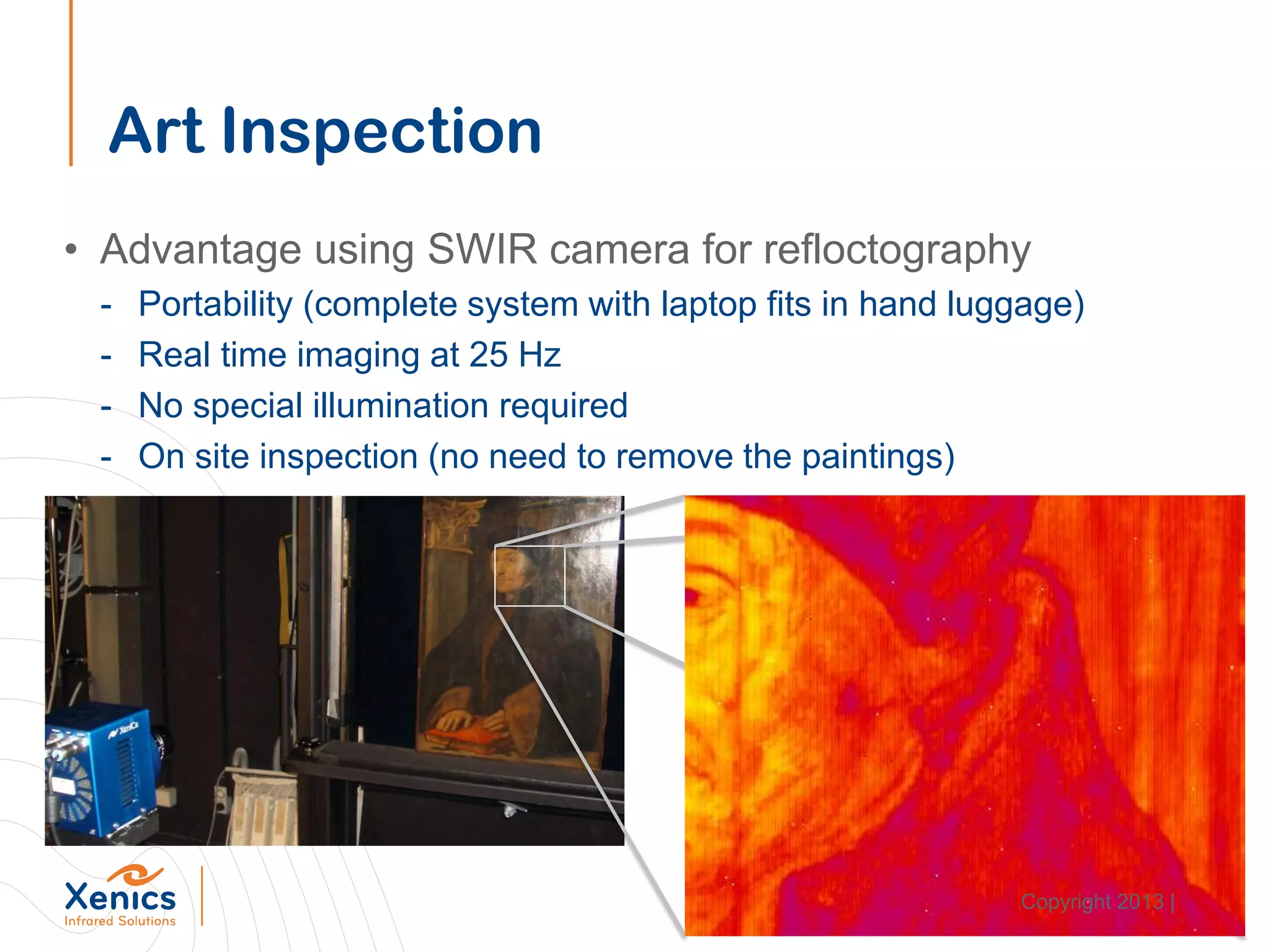
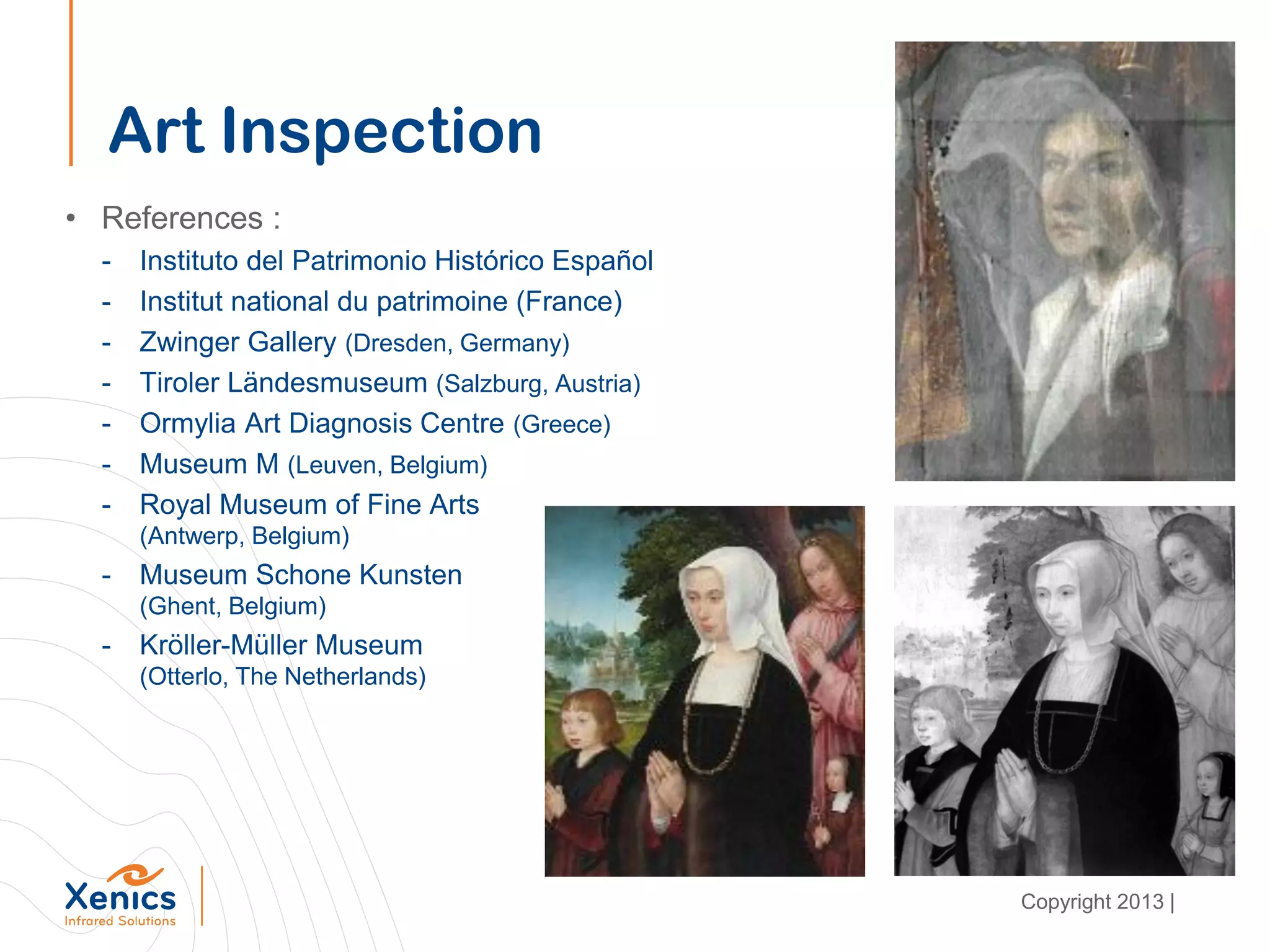
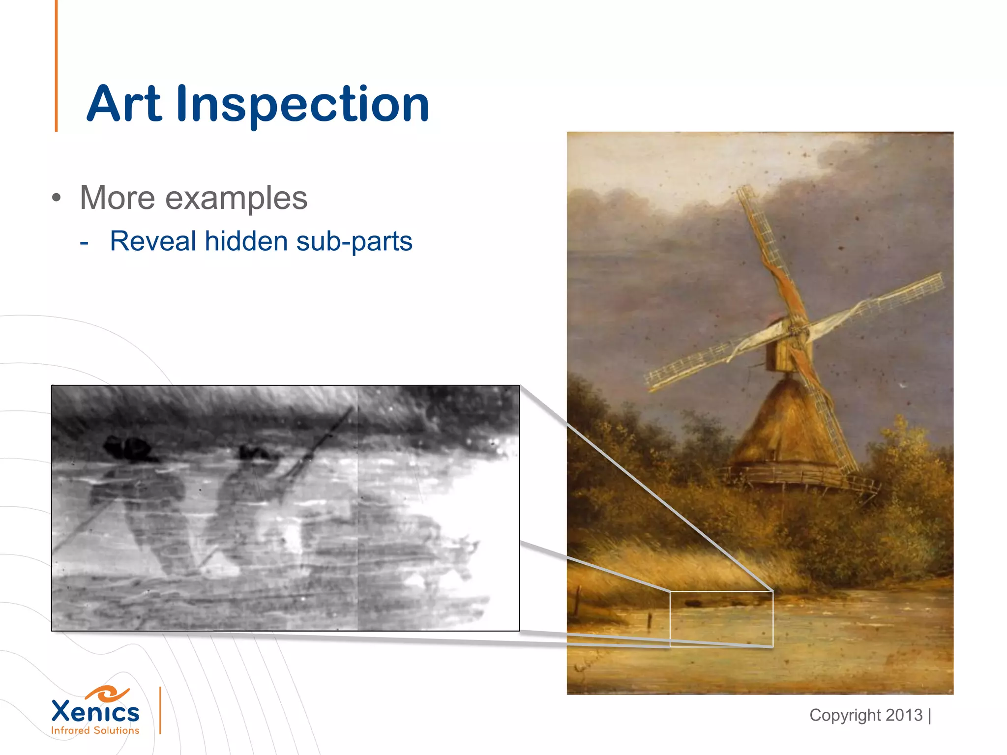
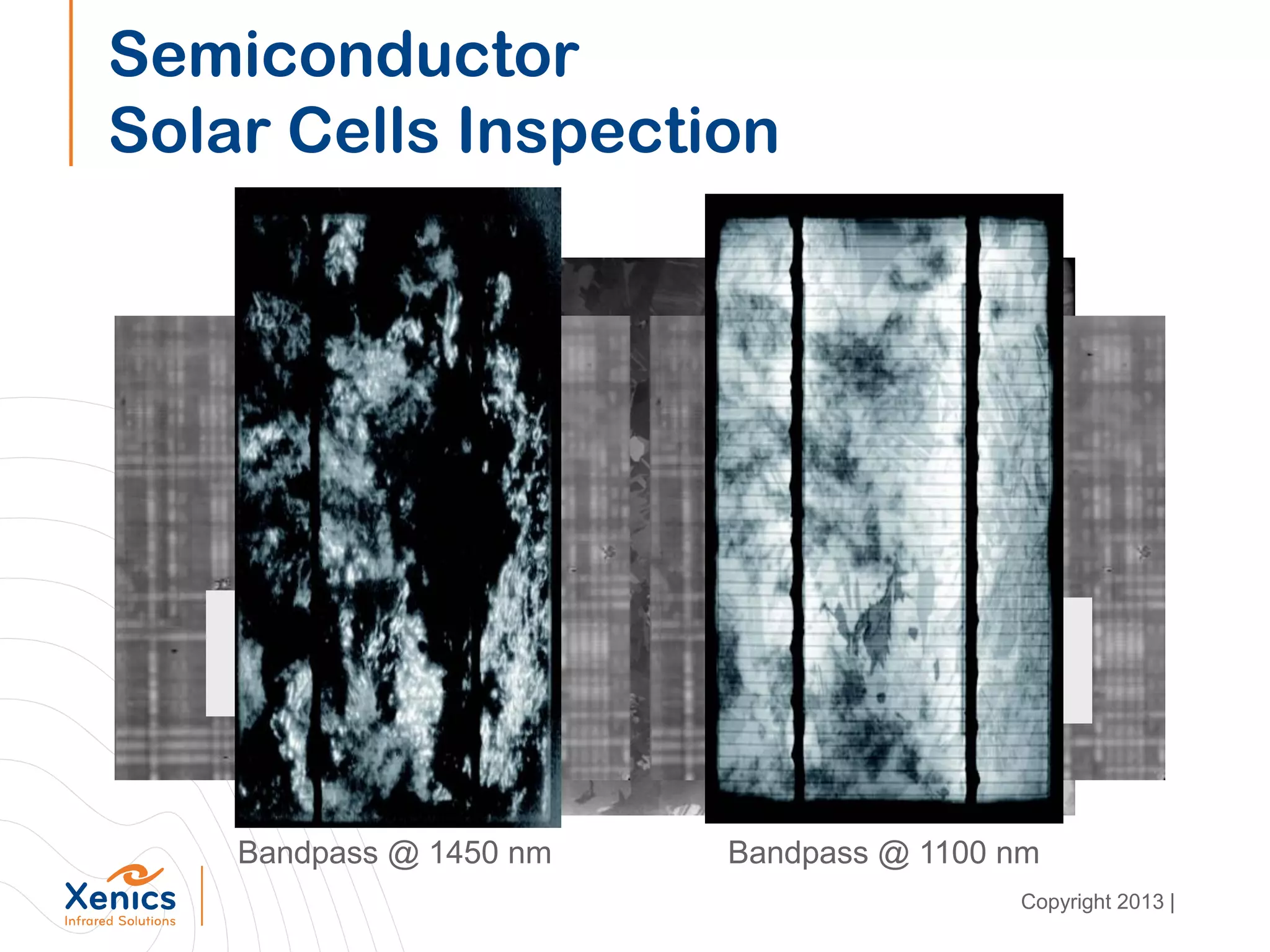
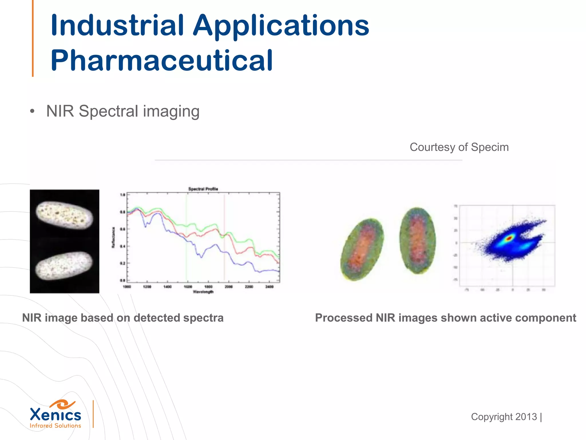
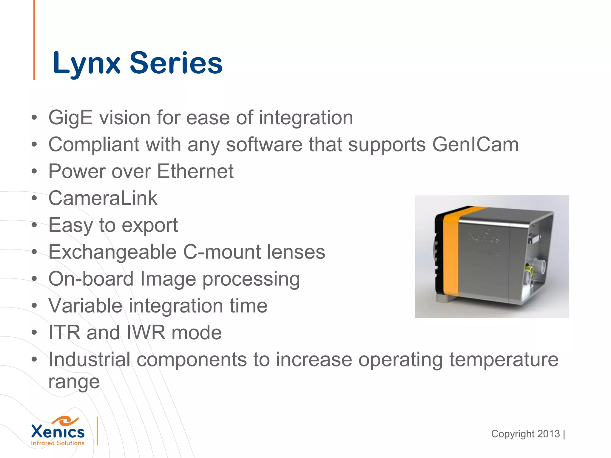
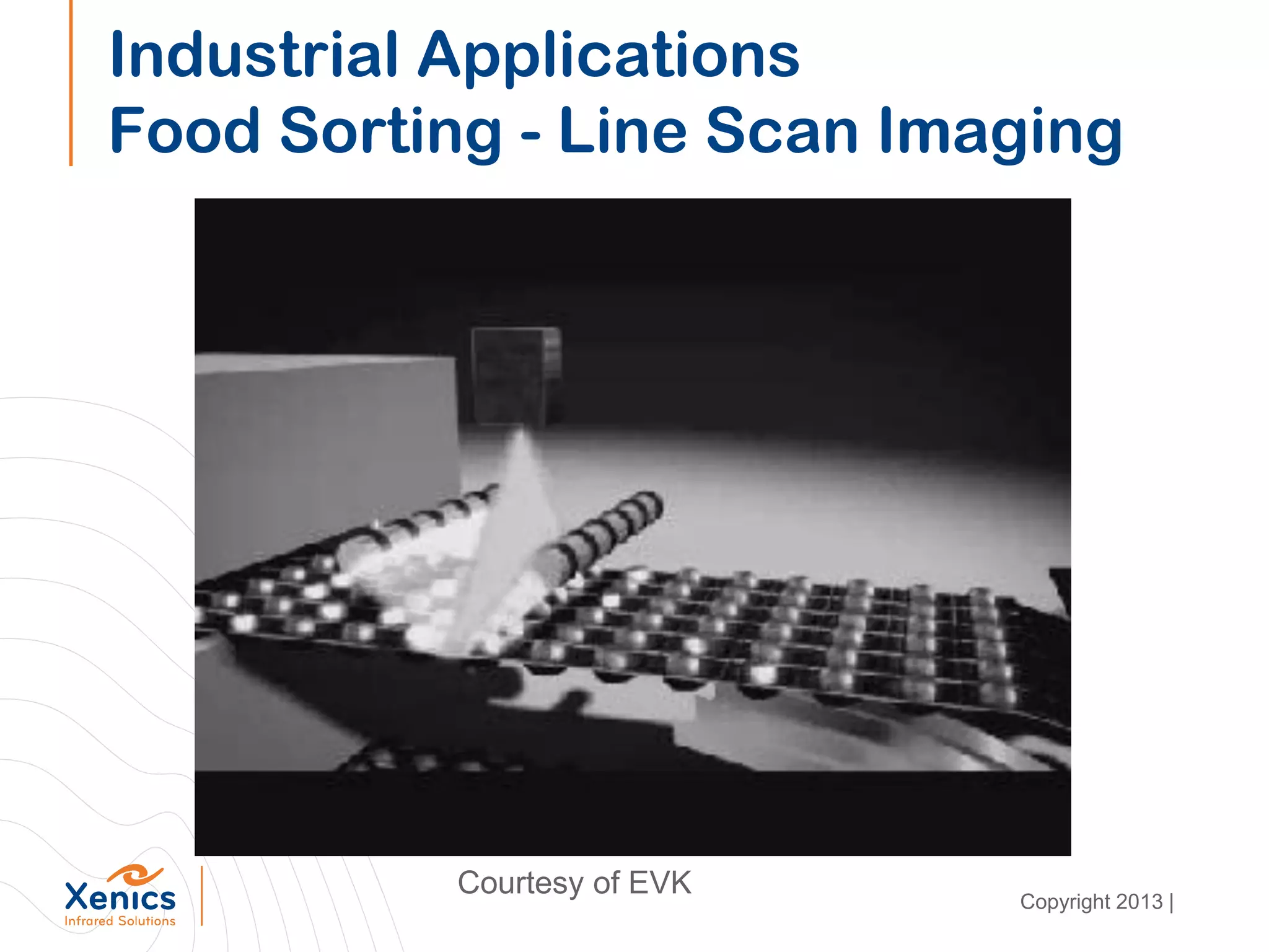
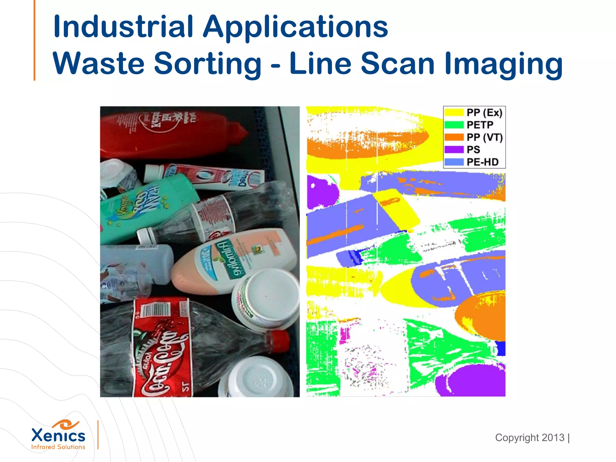
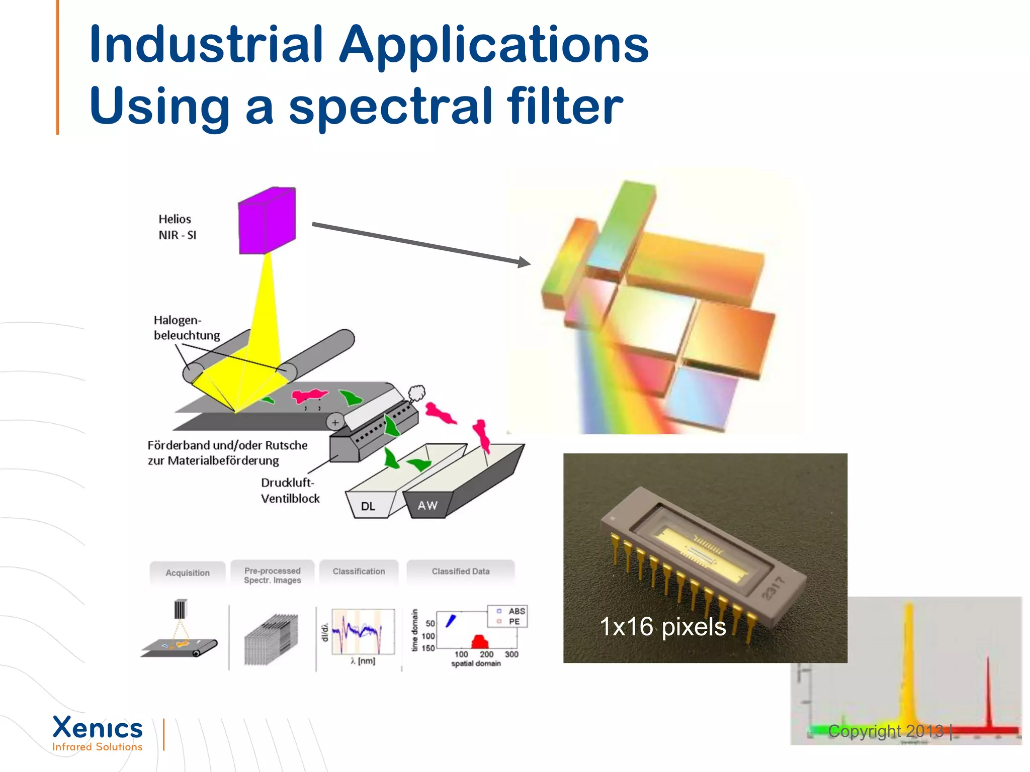
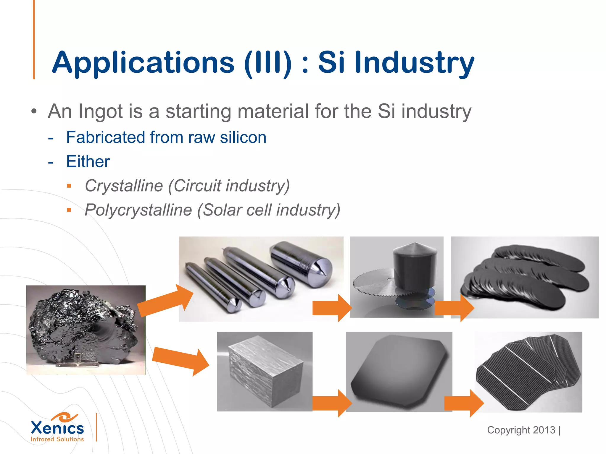
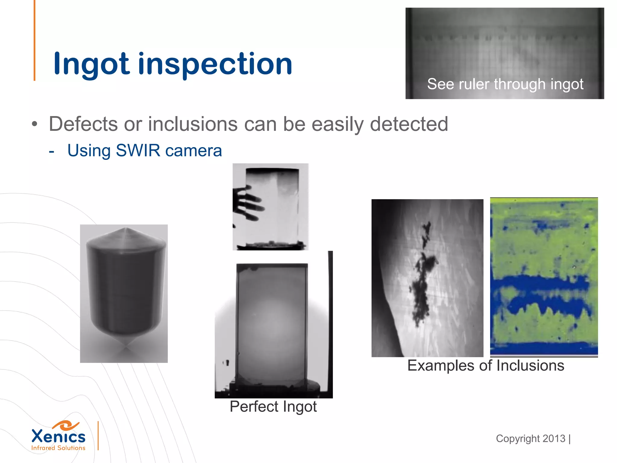
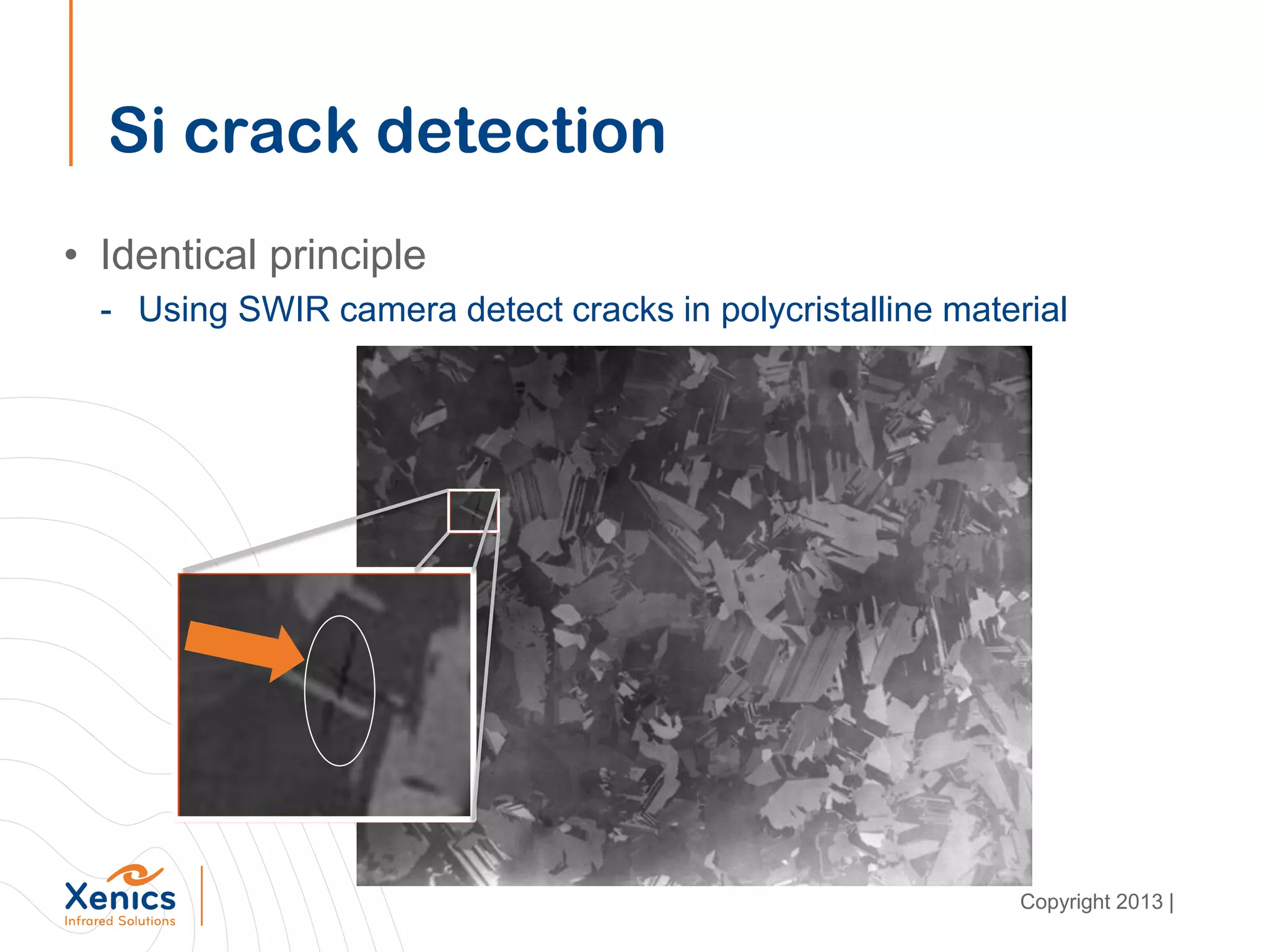
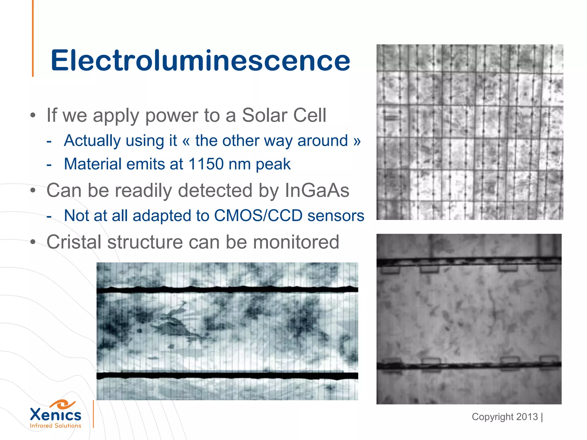
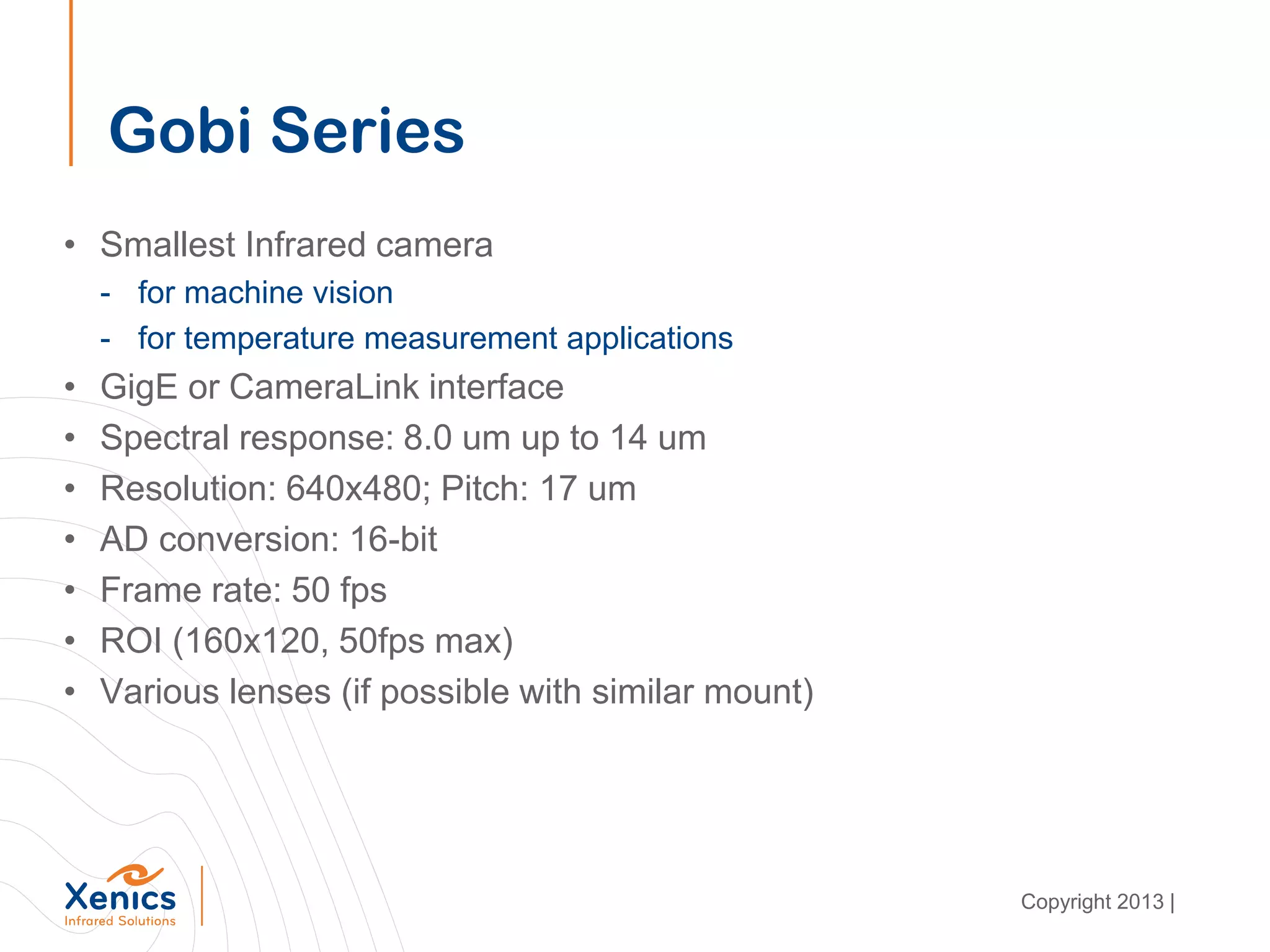
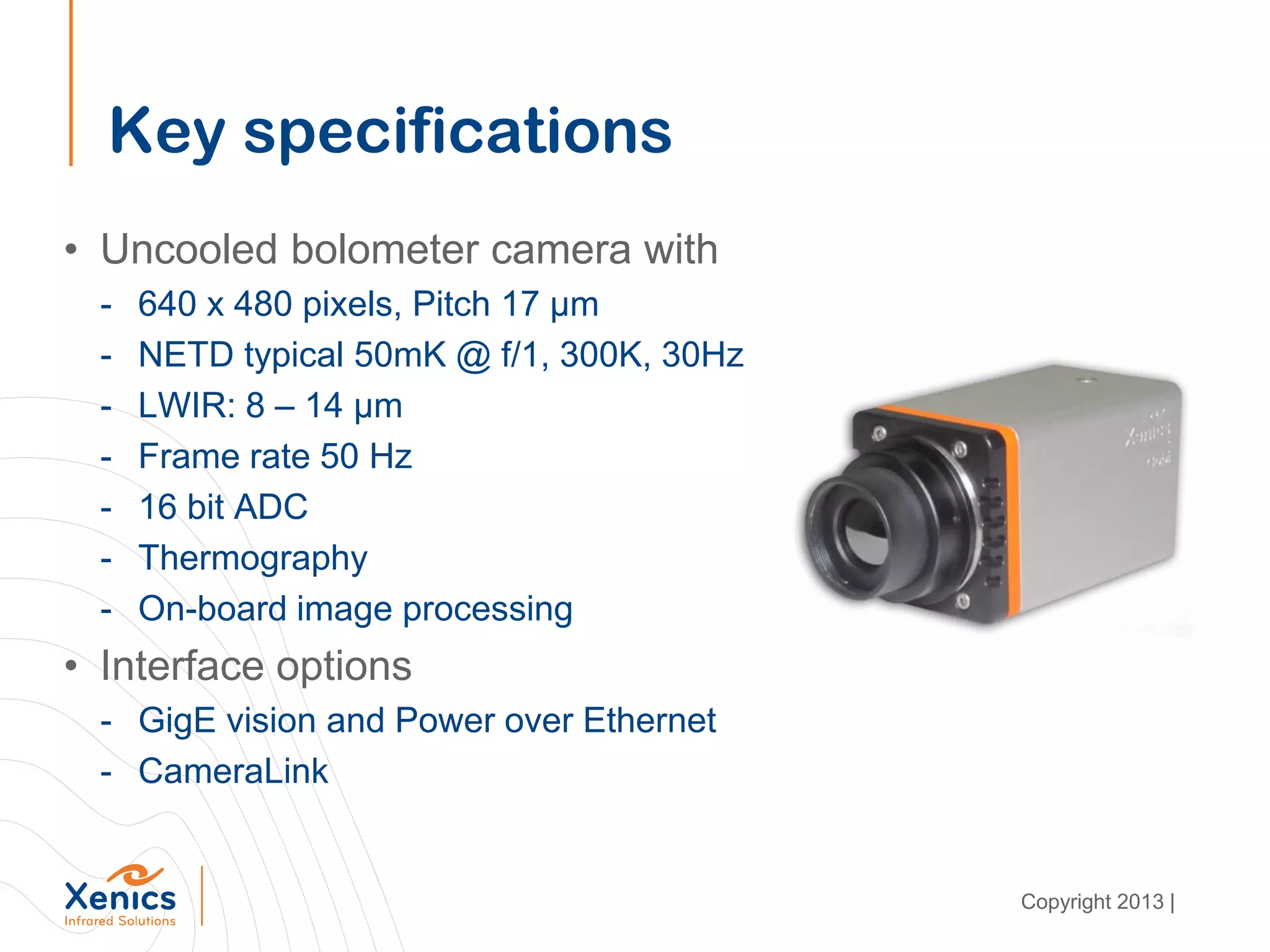
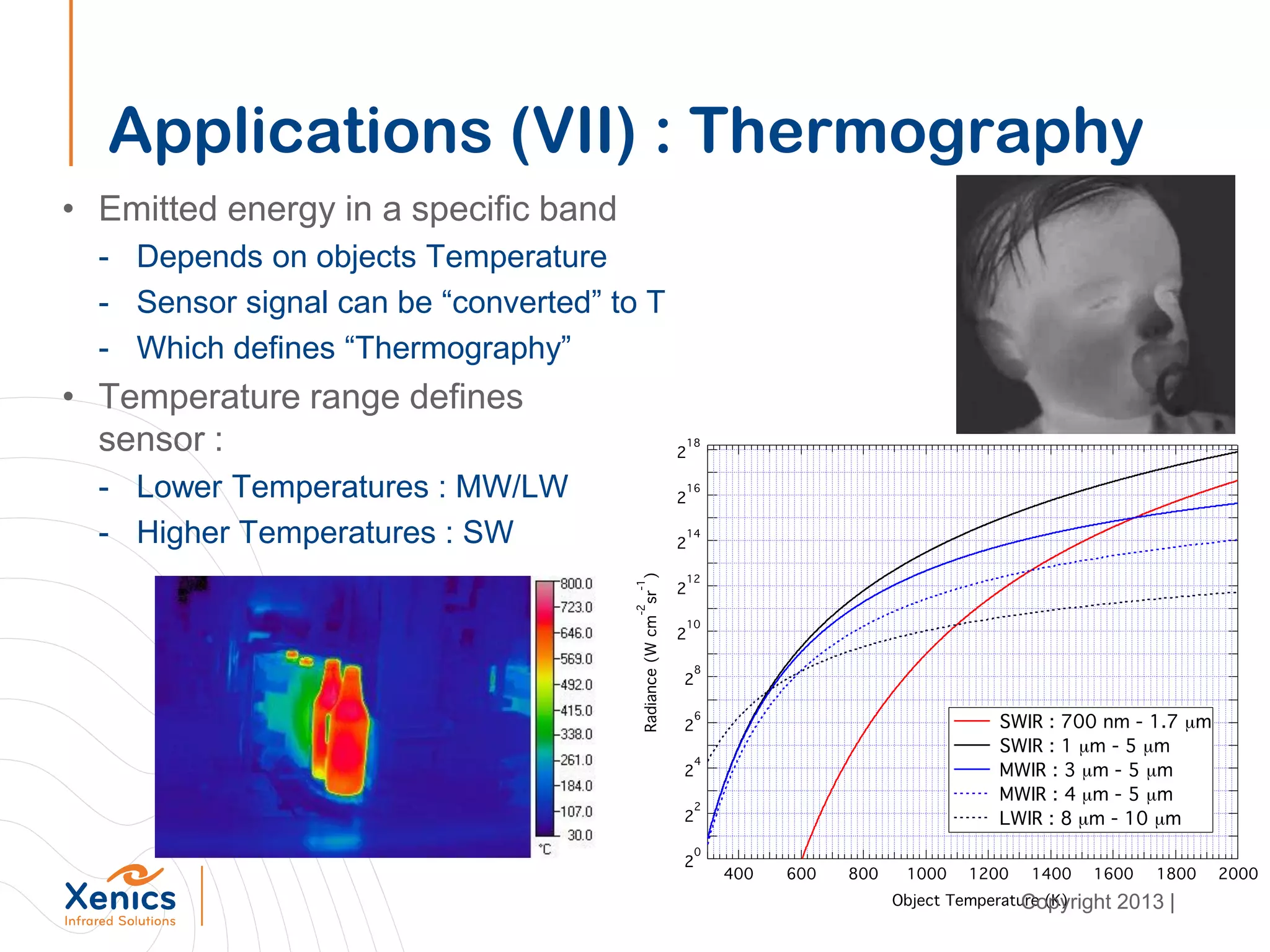
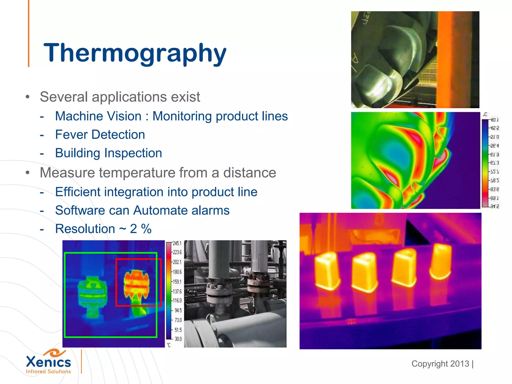
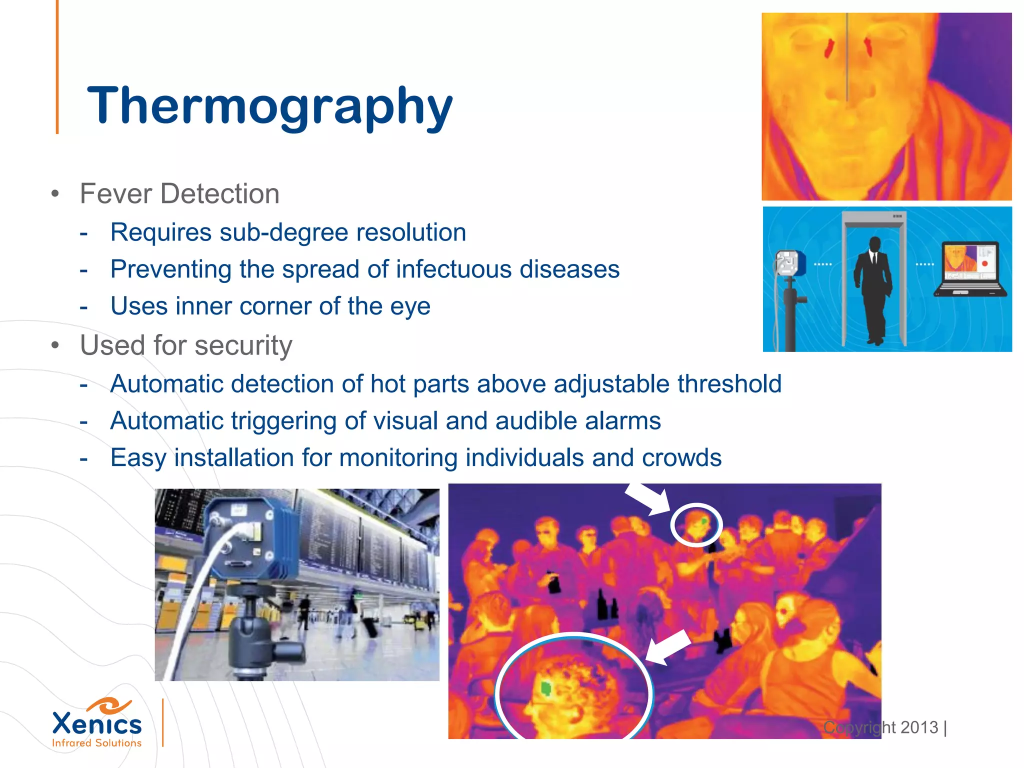
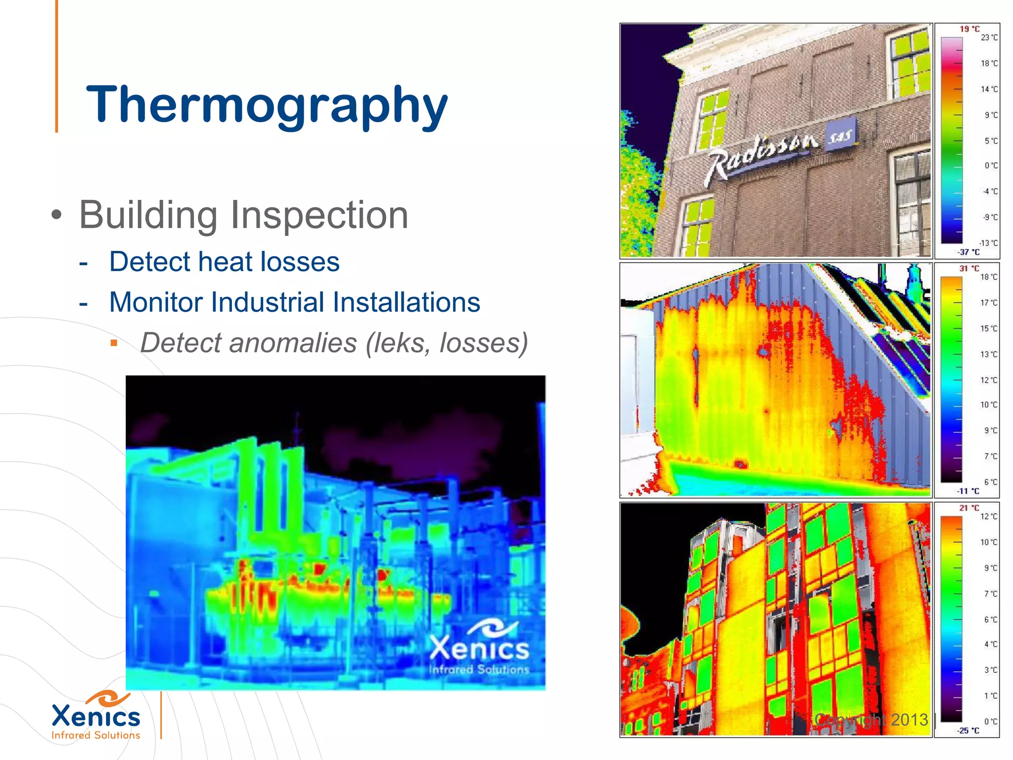
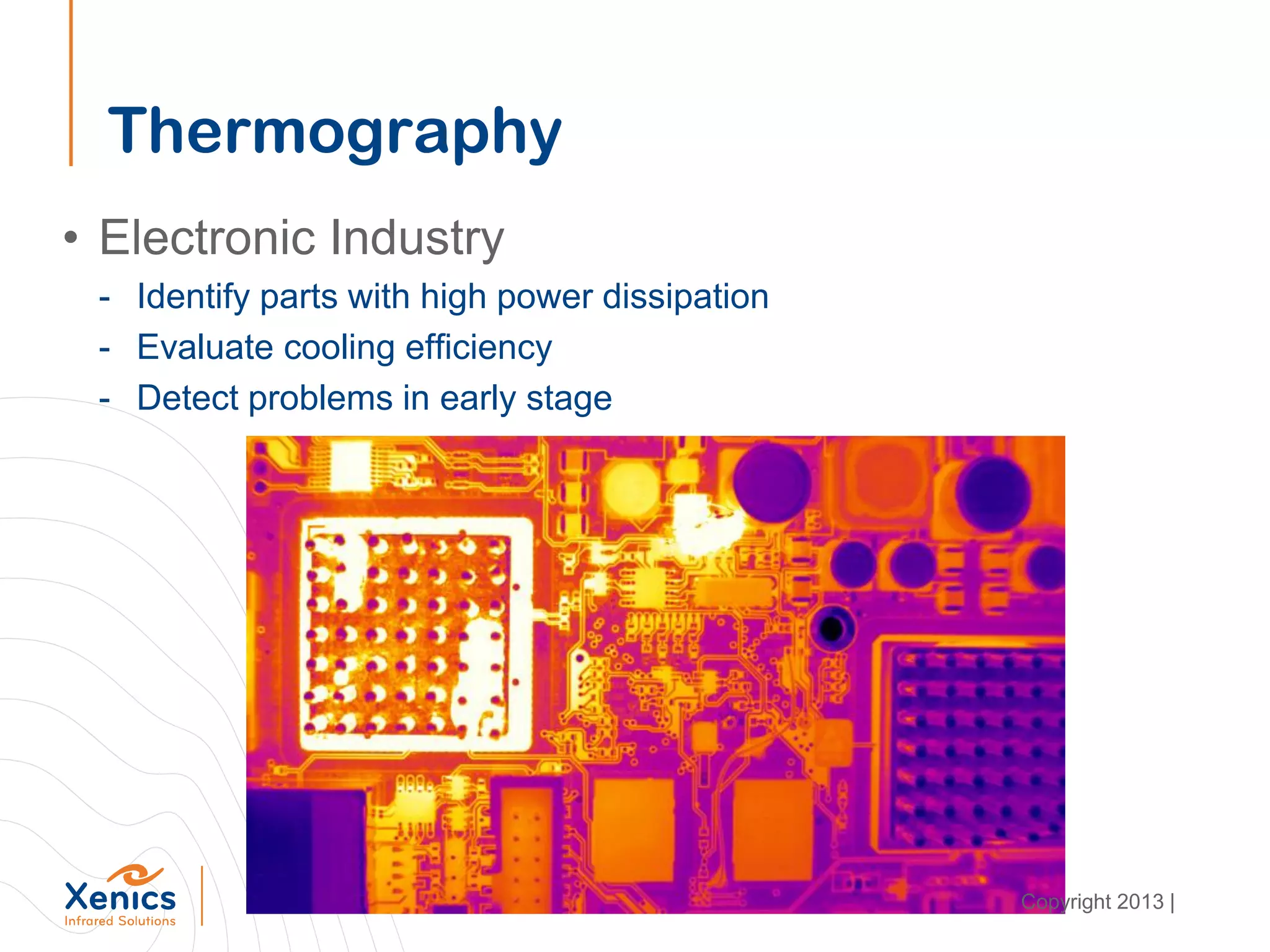
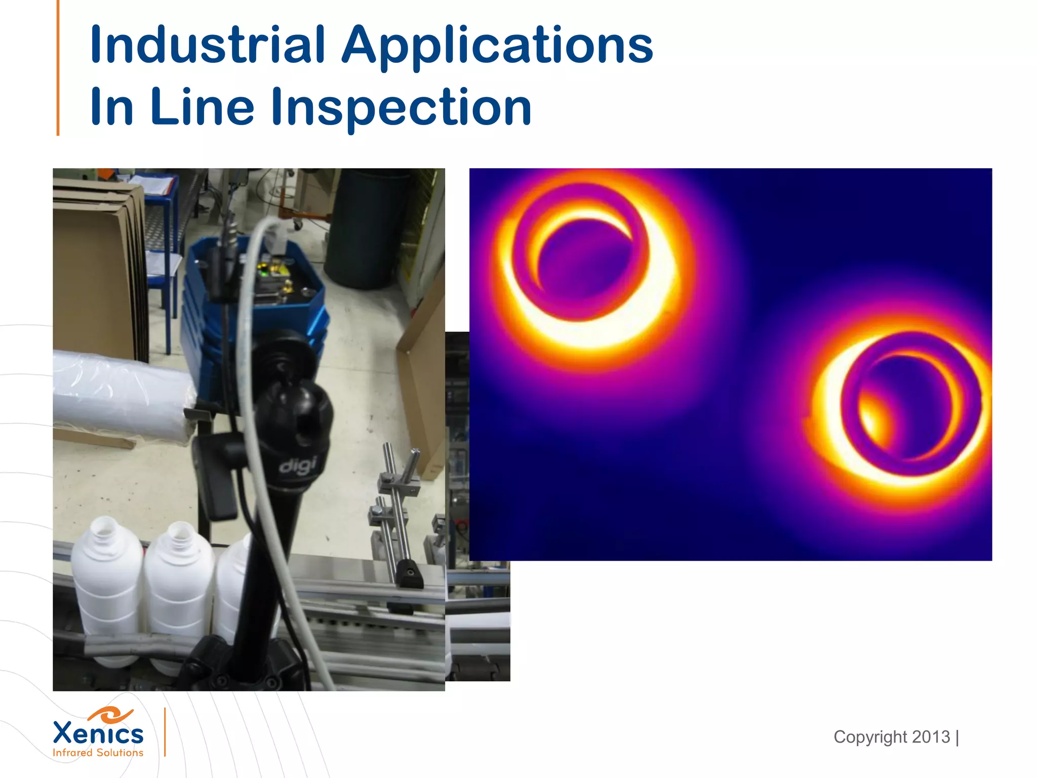
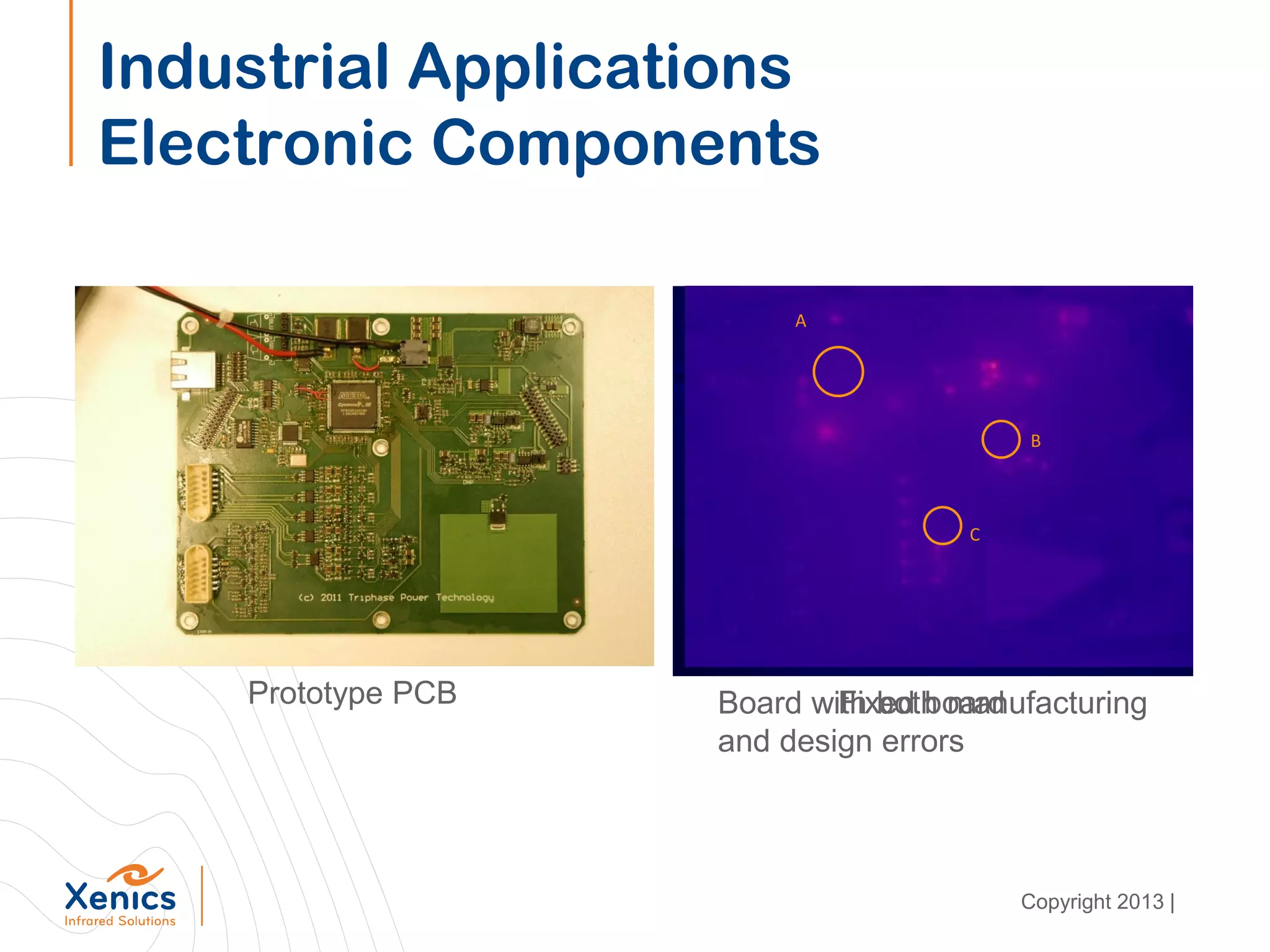
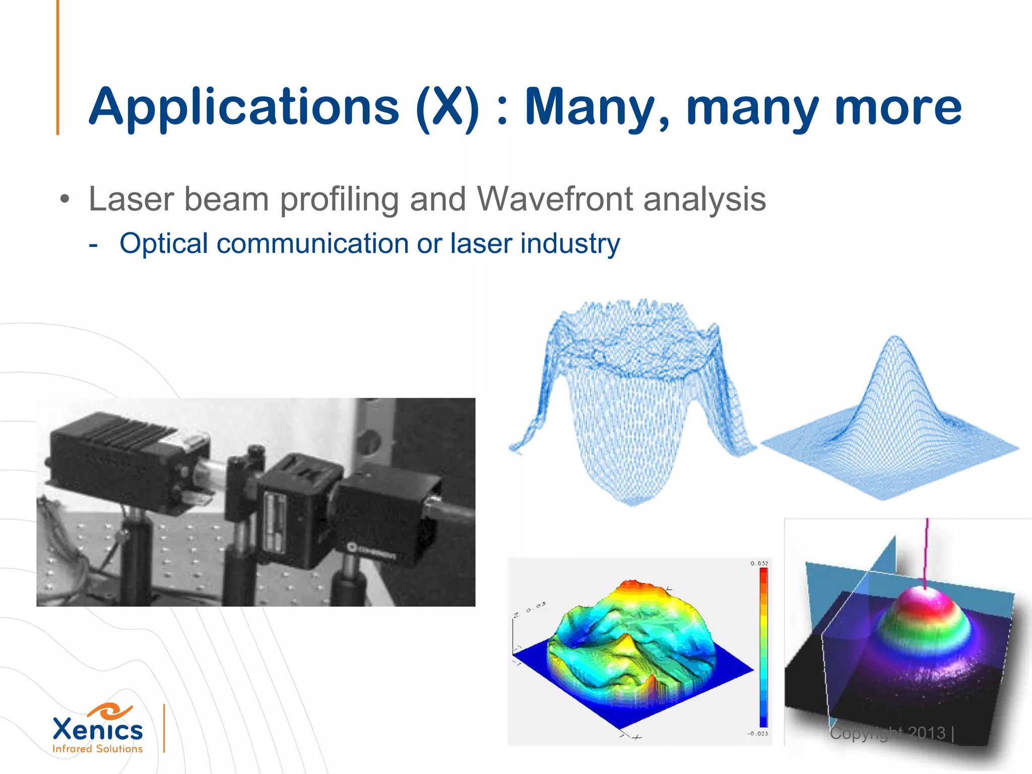
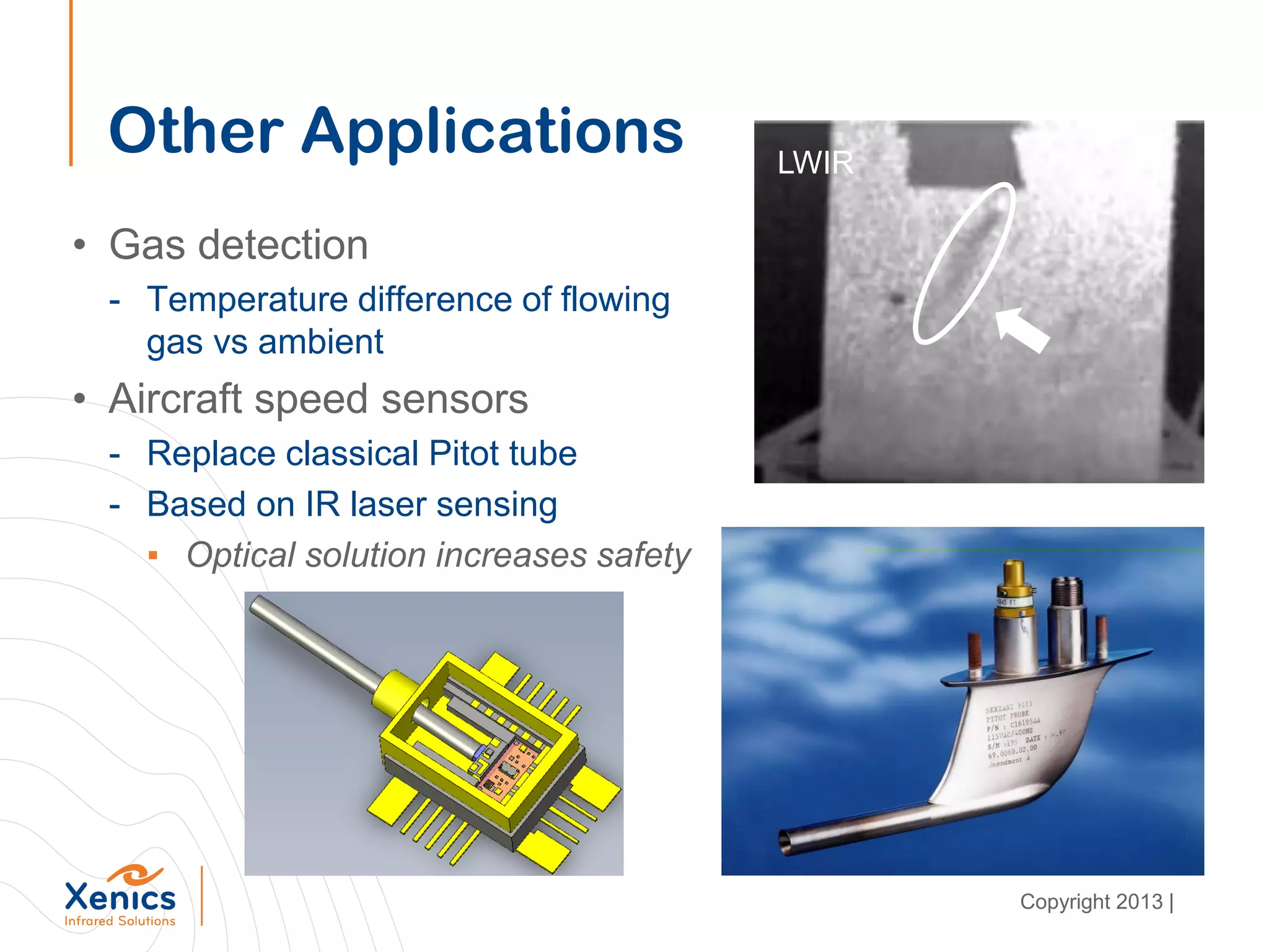
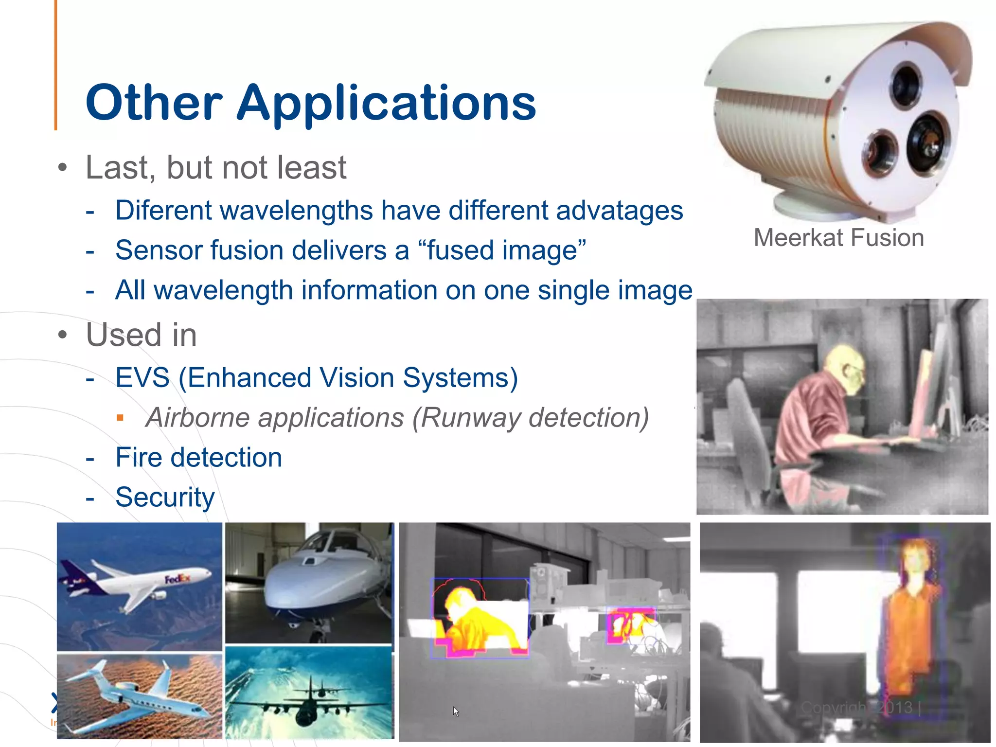
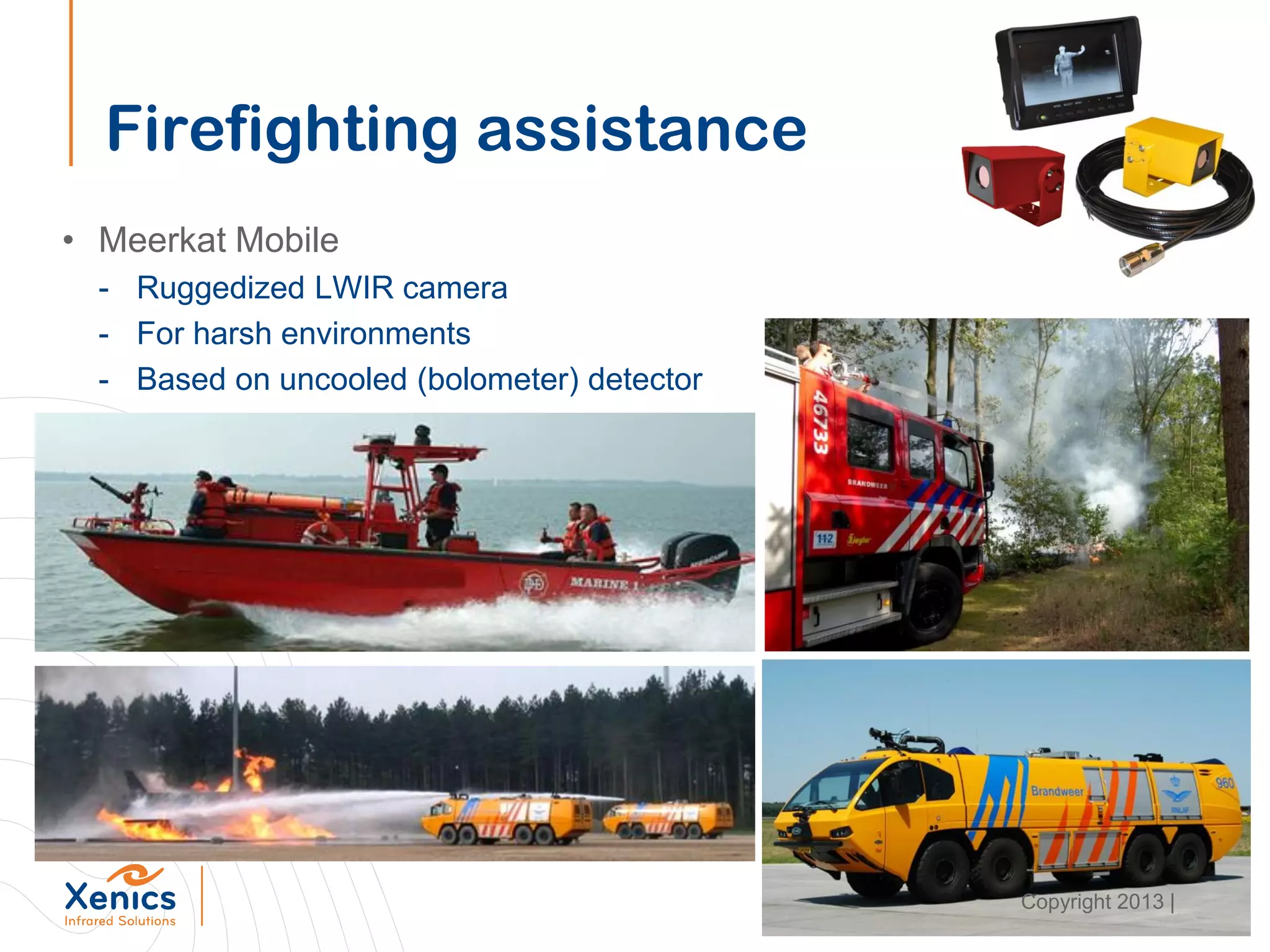
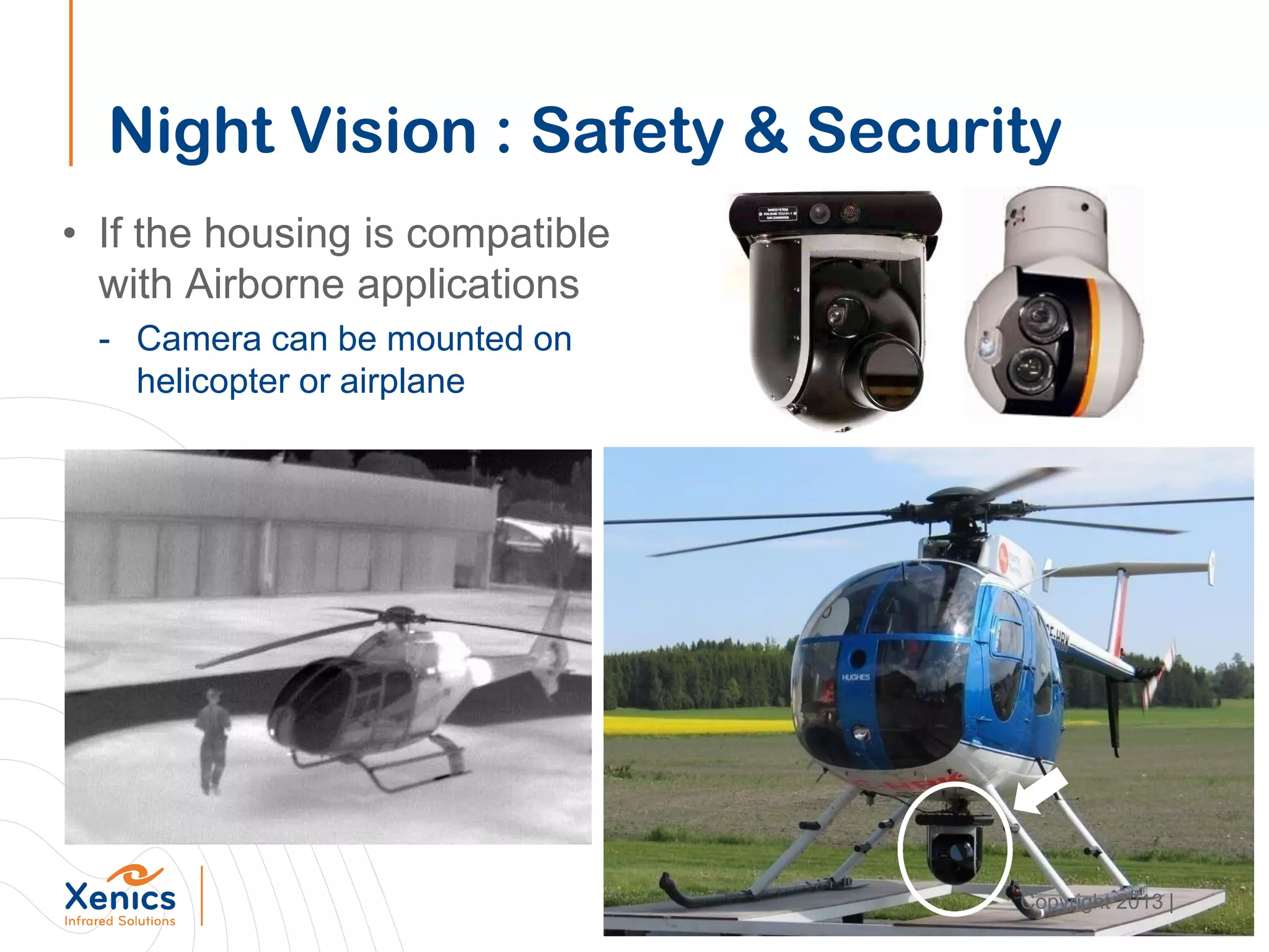
Xenics’s Smart Sensor Systems based on
modular design for Long Wave and Short Wave
InfraRed Applications
Overview
• Xenics in Short
• What is Infrared radiation?
• New camera archtecture
• Products Line Overview with applications
Copyright 2013 |
Module 1:
Xenics in Short
Mission Statement
Our mission is
• to be a leading provider of infrared cameras and detectors,
• based on a strong knowledge background of
infrared detector technology,
• achieved via continuous innovation,
• application and market driven, and
• combined with a flexibility towards our customers
to find a solution to their specific infrared problem.
Copyright 2013 |
Key Differentiators
Copyright 2013 |
Core Competences
Detector
technology
ROIC design
Electronics
Mechanics
Embedded
software
User software
Radiometry
Image
enhancement
Copyright 2013 |
Products & Services
• Standard products
- Systems
- Cameras
• OEM level products
- Camera cores
- Cooled engines
- Detectors
- ROICs
• Custom design
- Any detector type
- Cooled or un-cooled
Copyright 2013 |
Market & Product Segmentation
Copyright 2013 |
Product Families
• Xeva, XS (SWIR)
- TE-Cooled platform for InGaAs & MCT
• Cheetah-CL (SWIR)
- High Speed InGaAs real-time platform
• Onca (MWIR & LWIR)
- Platform for Stirling cooled engines
• Gobi & Raven (LWIR), Bobcat & Rufus (SWIR)
- Platform for uncooled bolometers and InGaAs
• XTM (LWIR) & XSW (SWIR)
- Xenics Cores
• Meerkat-Fix, Meerkat-Mobile
- Platforms for outdoor Security cameras
• Pµmair
- Gimbal Platform
Copyright 2013 |
Module 2:
What is Infrared Radiation
What is InfraRed radiation ?
• Sir Isaac Newton (1666)
• Studied light in all it’s aspects
• Conclusion :
- Visible light is not white
- It consists out of a spectrum of
different colours
- Spectrum ranges from
▪ Blue : 390 nm
▪ Red : 750 nm
Copyright 2013 |
What is InfraRed radiation ?
• Sir William Herschel (1800)
- Studied relation between
colour and temperature
• Wilhelm Wien (1900)
- Formulates his displacement law
- Relates temperature to wavelength
LWIR
MWIR
SWIR
Visible
Sun
Copyright 2013 |
What is InfraRed radiation ?
• Max Planck (1900)
- Nobel Prize for Physics 1918
- Radiance over wavelength
▪ For object temperature
LWIRMWIRSWIRVisible
Sun
Wien’s Law
Copyright 2013 |
Radiation
• Basically we know now that :
- There is radiation all around us
- It comes with nature (it is natural)
• Each type of radiation leads to
different applications
• Different domains can be
distinguished :
- Gamma, X-Rays, UV, IR, Radio, …
IR wavelength range
Copyright 2013 |
Transmission
• Not all radiation can “travel” free in space
- Different molecules “absorp” specific wavelengths
▪ Due to molecular interaction
- This creates so called “transmission windows”
▪ Only radiation from these zones is perceivable
Visible
LWIRSWIR MWIR
Copyright 2013 |
Imaging in the Visible range
• Very common
- Our eye is nicely matched to
the emitted radiation of the sun
• Imaging reflected sunlight
- Camera’s can readily capture light and
make images
Sun
Radiance
Copyright 2013 |
Imaging in the SWIR (I)
• Similar to imaging under sunlight
- Reflected light will form an image
• Now, two light sources are available
- Sunlight in the SWIR region
- Light from stars and moon
Sun
Radiance
Light in
SWIR region
Moonlight
Copyright 2013 |
Imaging in the SWIR (II)
• SWIR images are similar to visible ones
- Persons and objects can be recognized
• However :
- No Blue/Green/Red (gray)
- Imaging at night it possible
- Images depend on material behaviour at SWIR wavelengths
Copyright 2013 |
Imaging in the NIR/LWIR (I)
• In these wavelength ranges :
- Objects at colder temperatures emit power
▪ Remember Planck !
▪ Mainly 300 K (27 °C) and above
• This type of image will be “emitted”
- Can be captured in complete darkness
- Gives an impression of temperature
▪ We obtain a “thermal image”
- Difficult to identify people
Hot ColdIn between
Copyright 2013 |
Imaging in the NIR/LWIR (II)
• These wavelengths are usefull for
- Security applications
- Temperature monitoring
▪ From a distance
• Wavelength dependance of transmission
- Has an impact on image quality
3 - 5 µm
8 - 12 µm
Copyright 2013 |
How detect IR radiation ?
• We have to use a “Photo-Detector”
• A photo-detector has to convert :
- Incident radiation Pλ (W/m2)
- Into an output electrical signal
• This electrical signal can be :
- A resistance change ΔR
▪ In case of a photoconductor or a bolometer
- A photocurrent
▪ In case of a Photo Voltaic detector
Copyright 2013 |
Photo-Detectors - Detectivity
• D* for a large variety of detectors has been measured and mapped
• Theoretical (fundamental) limits are available
InGaAs
MCT
InSb
Copyright 2013 |
Thermal Detectors
• Operating principle :
- Incident radiation is absorbed
- The temperature of the device increases (ΔT)
▪ ΔT ~ 1 K for Pr ~ 0.25 mW
- The ΔT causes a measurable modification of an electrical parameter
• A well known type of thermal detector is the bolometer :
- The device is thermally isolated from the substrate
S=
DR/ R
Pl
Copyright 2013 |
Sensor Integration
• There exist two types of sensor integration :
- Monolithic integration
- Hybrid integration
• Hybrid integration :
- Detector array and readout
in different substrates.
- Subsequently joined
• Monolithic integration :
- Detector device(s) and ROIC
both integrated in the same substrate
• Xenics detectors are hybrid
Copyright 2013 |
Sensor Integration
• Monolithic integration :
- Easy to produce
- Same technology for both
- But optimization is difficult
• Hybrid integration :
- Detector can be fully optimized :
▪ III-V material for IR detection
▪ MEMS for accelerometers
▪ …
- Integration can be difficult :
▪ Carrier
▪ Flip-Chip technology
Copyright 2013 |
Sensor Packaging
• The next step is relatively easy
• The sensor is packaged in either :
- Ceramic substrate
- Metal can package
• A Metal Can package
- Allows hermetic sealing
- Better thermal behaviour
TE
C
Ceramic
Substrate
ROIC Detector
Copyright 2013 |
Module 3:
New Architecture
New Architecture
• Focus on Machine Vision market
• New Line of small optimized IR Sensors Systems
• Based on Modular Design
• SWIR InGaAs Linear and Area Scan
• LWIR Bolometer Area Scan
Copyright 2013 |
Origin of the Architecture
• New Generation of Sensors
- More dynamic range
- Lower noise
- More compact
• Modularity
- Platform for variation on video output
- Platform for variation on sensor type
- Platform for variation on on-board processing
• Compactness
• Manufacturing
• Market price
Copyright 2013 |
Sensor Boards
• First step in camera development :
- Sensor interface
• This PCB contains :
- Signal conditioning
▪ Receive sensor signals
▪ Guarantee signal integrity
- Circuit bias elements
▪ Provide required electrical signals
Bolometer
Interface
Line Array
Interface
2D Array
Interface
Copyright 2013 |
Processing Board
• FPGA board
- Provides digital interface
▪ Based on user settings
- Collects digitized signal
- Implements required algorithms
▪ NUC (Non-Uniformity Correction)
▪ Shutter and cooler control
▪ Thermography
- Provides output signal
▪ In correct data format
▪ GigE/CL/Avid/BT.656/…
Copyright 2013 |
Camera construction (III)
• The output interface :
- Receives output from FPGA board
- Collects users settings
▪ Over serial interface
▪ Trigger signal
- Will generate
▪ Required power supply voltages
- From external power source
- From Ethernet (PoE)
▪ All required outputs
- CameraLink
- GigE
- Analog Video
- CoaXpress
- Output Trigger
Analog
Video
Camera
Link
GigE/PoE
Copyright 2013 |
Final Assembly (I)
• All these components are compatible
• Allow construction of different configurations
- Cold finger (cooled devices)
- Shutter (if required)
• Basic version is an OEM Module
Copyright 2013 |
Final Assembly with Housing
• To obtain a camera, the stack is combined with
- Housing
- Front (for lens mount)
Copyright 2013 |
Flexibilty for Integration
• Mechanics
- Same physical size
• Xeneth SDK and API
- Common set of instructions
• Xeneth Support of Frame Grabber
- National Instruments
- Euresys
• GigE Software Compatibility
- MvTec Halcon
- Cognex Vision Pro
- Stemmer CVB
• Large Choice of Lenses
Copyright 2013 |
Module 4:
Product Family with Applications
Overview
• SWIR
- Bobcat 640
- Lynx-512
- Lynx-1024
- Lynx 2048
• LWIR
- Gobi-640
- Gobi-384
• Interfaces
- GigE
- CameraLink
- CoaXpress
Copyright 2013 |
Bobcat 640
• Smallest SWIR camera for machine vision applications
• GigE, CameraLink or CoaXpress interface
• Spectral response: 0.9 µm up to 1.7 µm
• VisNIR option: 0.5 µm up to 1.7 µm
• Resolution: 640 x 512; Pitch: 20 µm
• AD conversion: 14-bit
• TE-1 cooled
• Frame rate: 100 fps
• ROI
• Various C-mount lenses
Copyright 2013 |
• GigE vision for ease of integration
• Compliant with any software that supports GenICam
• Power over Ethernet
• CameraLink
• Easy to export
• Exchangeable C-mount lenses
• On-board Image processing
• Variable integration time
• ITR and IWR mode
• VisNIR option
• Industrial components to increase operating temperature range
Bobcat 640
Copyright 2013 |
Art Inspection
• Advantage using SWIR camera for refloctography
- Portability (complete system with laptop fits in hand luggage)
- Real time imaging at 25 Hz
- No special illumination required
- On site inspection (no need to remove the paintings)
Copyright 2013 |
Art Inspection
• References :
- Instituto del Patrimonio Histórico Español
- Institut national du patrimoine (France)
- Zwinger Gallery (Dresden, Germany)
- Tiroler Ländesmuseum (Salzburg, Austria)
- Ormylia Art Diagnosis Centre (Greece)
- Museum M (Leuven, Belgium)
- Royal Museum of Fine Arts
(Antwerp, Belgium)
- Museum Schone Kunsten
(Ghent, Belgium)
- Kröller-Müller Museum
(Otterlo, The Netherlands)
Copyright 2013 |
Art Inspection
• More examples
- Underlying scetch
Copyright 2013 |
Art Inspection
• More examples
- Reveal hidden sub-parts
Copyright 2013 |
Semiconductor
Solar Cells Inspection
Defective Transistor
Power IC = ON
Defective Transistor
Power IC = OFF
Bandpass @ 1100 nmBandpass @ 1450 nm
Copyright 2013 |
Industrial Applications
Food Industry
Classification
Greenish:
Higher moisture,
Softer
Reddish:
Lower moisture,
higher protein,
Harder
Heterogenous
sample sets
Courtesy of ITRES, published in Photonics Spectra
Copyright 2013 |
Industrial Applications
Pharmaceutical
• NIR Spectral imaging
NIR image based on detected spectra Processed NIR images shown active component
Courtesy of Specim
Copyright 2013 |
Lynx Series
• Smallest SWIR line scan camera for machine vision
• GigE, CameraLink or CoaXpress interface
• Spectral response: 0.9 µm up to 1.7 µm
• Resolution: 512; Pitch: 25 µm, 1024; Pitch: 25 µm and
2048; Pitch: 12,5 µm
• AD conversion: 14-bit
• Un-cooled
• Frame rate: 40 kHz or 10 kHz
• Various Gain modes
• Uncooled
• Various C-mount lenses, optional U-mount
Copyright 2013 |
Lynx Series
• GigE vision for ease of integration
• Compliant with any software that supports GenICam
• Power over Ethernet
• CameraLink
• Easy to export
• Exchangeable C-mount lenses
• On-board Image processing
• Variable integration time
• ITR and IWR mode
• Industrial components to increase operating temperature
range
Copyright 2013 |
Industrial Applications
Food Sorting - Line Scan Imaging
Courtesy of EVK Copyright 2013 |
Industrial Applications
Waste Sorting - Line Scan Imaging
Copyright 2013 |
Industrial Applications
Using a spectral filter
1x16 pixels
Copyright 2013 |
Applications (II) : OCT
• Optical Coherence Tomography
• Invented in 1991
- MIT – Prof James Fujimoto
• Very similar to ultrasound
- Use fs light pulses instead of sound
• Provides high resolution images
- Opaque Samples
- Depth information (6 mm)
- Generate image “cubes”
• (ND) Non-Destructive technique
Prof James Fujimoto
Image : Heidelberg Engineering
Copyright 2013 |
OCT Principle : LCI
• Low Coherence Interferometry
- Two distinct beams
• Reference Beam
- Passes through optical delay-line
• Sample Beam
- Reflected by Reflector Sample
• Interference @ Detector
- Pattern contains information
about layer composition
Copyright 2013 |
OCT : Spectral Interferometry
• Identical principle
- Two distinct beams
- But now mirror is fixed
• Spectral response can be captured
- Using detector line-array
• Fourrier transform
- contains information about
layer composition
Copyright 2013 |
OCT : 2D surface imaging
• With either technique
- Time domain or Spectrum based
- Provides information on 1 point
• Add scanning motion
- Build Line or 2D depth profile
• Some limitations :
- Axial resolution can be good (< 10 µm)
- Lateral resolution is limited (20 µm)
- Axial scanning must be rapid
(fringe blurring)
- Lateral scanning is necessarily slower
(~ 1 second per scan)
Copyright 2013 |
• Most surfaces cannot be
penetrated with optical rays
- CMOS and CCD devices not suited
• But : SWIR (@ 1550 nm) can !
- Compatible wit InGaAs
• Fast 2D camera is required
- Speed of scan
- Axial resolution
- Deliver a 3D section without mechanical scanning
• Currently one camera is compatible with FF OCT
- Xenics Cheetah-640CL (1,730 fps)
Infrared Based OCT
Copyright 2013 |
Examples : Medical Imaging (I)
• Perfect to image structures in
the eye
- Non-invasive optical imaging with
- Millimeter penetration
- Submicron resolution
• Real time imaging possible
• Very popular in eye clinics
- 20 000 ophtalmic OCT systems
- 2 000 new installations each year
Copyright 2013 |
• Blood vessel imaging
• High resolution images
- Using catheder
- Detect coronary artery diseases
• OCT
- Expected to replace ultrasound
- Provides 10 x better resolution
(4 – 20 μm vs 110 μm)
• Clear and detailed image shows
- Layered structure of the blood vessel wall
- Intima (I), Media (M), and adventitia (A)
Examples : Medical Imaging (II)
Image : Thor Labs
Copyright 2013 |
• OCT in Dentistry
• Detecting failing composite
- Voids and fractures visible
• Image comparison
- X-ray (left)
- OCT in background
- Plain view (right)
Examples : Medical Imaging (III)
Image : Lantis Laser
Copyright 2013 |
• In the near future :
- Handheld OCT device to visualize and map non-melanoma skin
cancer (NMSC) under the skin
- Early detection and treatment possible
Examples : Medical Imaging (IV)
Image : www.octnews.org
Copyright 2013 |
• New and innovative for quality assurance
- Non-Destructive inspection technique
- On-the-fly monitoring
- Inspect manufacturing and assembly processes
• Delivers cross-sectional images
• MEMS pressure sensor
- Several cross sections
- At various depth levels
OCT for industrial applications (I)
Copyright 2013 |
• Fraunhofer-Institut ILT
- OCT to investigate material
properties
- Test on plastic wall samples of a
liquids container
- 3 layers thick,
including 100 µm diffusion barrier
• Achievements :
- Thickness and uniformity of each layer
- In real time during a production
- Higher process security,
• Potential of large savings in production facilities
OCT for industrial applications (II)
Copyright 2013 |
Applications (III) : Si Industry
• Si is transparant for SWIR radiation
• This property can be exploited :
- See through Silicon (look behind)
- Inspect quality of the crystal (look inside)
Copyright 2013 |
Applications (III) : Si Industry
• An Ingot is a starting material for the Si industry
- Fabricated from raw silicon
- Either
▪ Crystalline (Circuit industry)
▪ Polycrystalline (Solar cell industry)
Copyright 2013 |
Ingot inspection
• Defects or inclusions can be easily detected
- Using SWIR camera
Examples of Inclusions
See ruler through ingot
Perfect Ingot
Copyright 2013 |
Si crack detection
• Identical principle
- Using SWIR camera detect cracks in polycristalline material
Copyright 2013 |
Electroluminescence
• If we apply power to a Solar Cell
- Actually using it « the other way around »
- Material emits at 1150 nm peak
• Can be readily detected by InGaAs
- Not at all adapted to CMOS/CCD sensors
• Cristal structure can be monitored
Copyright 2013 |
Electroluminescence
• If we monitor only radiation at 1450 nm
- We can observe lattice defects
Copyright 2013 |
Inspection and Circuit defects
• Using the same techniques
- BGA soldering quality inspection (through silicon)
- Circuit defect detection (forward biased junctions)
BGA grid inspection Defect Detection
Copyright 2013 |
Photon Emission Microscopy
• Failure analysis technique
- Localization of defects in semiconductor devices
- Detect leaky junctions
- Spot contact spiking (due to ESD)
- Also latch-up, oxide breakdown
• Requires dedicated sensor (SWIR)
- Low noise
- Low dark current
- Has to be cooled to LNT
Xenics corporate presentation Copyright 2013 |
Applications (IV) : Spectral sensing
• Spectrometry
- “Splits” light into basic components
• Shows
- What λ a material absorbs or reflects
- Consequentially what material it is
l1 ln
Incoming light
Spectrum
Grating
2012 | 71
Copyright 2013 |
Spectroscopy
• Spectral information is used to “colour” the image
• Different materials can be readily identified
Source : Carinthian Tech Research
Copyright 2013 |
Spectroscopy
• Typical “Machine Vision” application :
- Waste sorting
- Fruit or food monitoring (freshness)
Copyright 2013 |
Hyperspectral imaging
• Identical to Spectroscopy
- But for each individual pixel
- On one line
• Very usefull
- It delivers an image
- Tells us what is on the image
- Delivers us a “cube”
▪ 2D : image
▪ 3D : spectral information
l x
Incoming light
Spectrum
Grating
Copyright 2013 |
Hyperspectral imaging
• Very interesting for material observation or identification
• But also for defence
- Camouflage detection : distinguish natural from man-made
True Color Minerals I Minerals II
Copyright 2013 |
Gobi Series
• Smallest Infrared camera
- for machine vision
- for temperature measurement applications
• GigE or CameraLink interface
• Spectral response: 8.0 um up to 14 um
• Resolution: 640x480; Pitch: 17 um
• AD conversion: 16-bit
• Frame rate: 50 fps
• ROI (160x120, 50fps max)
• Various lenses (if possible with similar mount)
Copyright 2013 |
Key specifications
• Uncooled bolometer camera with
- 640 x 480 pixels, Pitch 17 μm
- NETD typical 50mK @ f/1, 300K, 30Hz
- LWIR: 8 – 14 μm
- Frame rate 50 Hz
- 16 bit ADC
- Thermography
- On-board image processing
• Interface options
- GigE vision and Power over Ethernet
- CameraLink
Copyright 2013 |
Applications (VII) : Thermography
• Emitted energy in a specific band
- Depends on objects Temperature
- Sensor signal can be “converted” to T
- Which defines “Thermography”
• Temperature range defines
sensor :
- Lower Temperatures : MW/LW
- Higher Temperatures : SW
Copyright 2013 |
Thermography
• Several applications exist
- Machine Vision : Monitoring product lines
- Fever Detection
- Building Inspection
• Measure temperature from a distance
- Efficient integration into product line
- Software can Automate alarms
- Resolution ~ 2 %
Copyright 2013 |
Thermography
• Fever Detection
- Requires sub-degree resolution
- Preventing the spread of infectuous diseases
- Uses inner corner of the eye
• Used for security
- Automatic detection of hot parts above adjustable threshold
- Automatic triggering of visual and audible alarms
- Easy installation for monitoring individuals and crowds
Copyright 2013 |
Thermography
• Building Inspection
- Detect heat losses
- Monitor Industrial Installations
▪ Detect anomalies (leks, losses)
Copyright 2013 |
Thermography
• Electronic Industry
- Identify parts with high power dissipation
- Evaluate cooling efficiency
- Detect problems in early stage
Copyright 2013 |
Industrial Applications
In Line Inspection
Copyright 2013 |
Industrial Applications
Predictive Maintenance
Copyright 2013 |
Industrial Applications
Electronic Components
Prototype PCB Board with both manufacturing
and design errors
B
C
A
Fixed board
A
B
C
Copyright 2013 |
Applications (X) : Many, many more
• Laser beam profiling and Wavefront analysis
- Optical communication or laser industry
Copyright 2013 |
Other Applications
• Wavefront sensing
- Drive adaptive optics
• Ultra fast imaging
- 80 ns integration times
- Allows for depth profiling
Copyright 2013 |
Other Applications
• Gas detection
- Temperature difference of flowing
gas vs ambient
• Aircraft speed sensors
- Replace classical Pitot tube
- Based on IR laser sensing
▪ Optical solution increases safety
LWIR
Copyright 2013 |
Other Applications
• Last, but not least
- Diferent wavelengths have different advatages
- Sensor fusion delivers a “fused image”
- All wavelength information on one single image
• Used in
- EVS (Enhanced Vision Systems)
▪ Airborne applications (Runway detection)
- Fire detection
- Security
Meerkat Fusion
Copyright 2013 |
Module 4:
Conclusion
Firefighting assistance
• Meerkat Mobile
- Ruggedized LWIR camera
- For harsh environments
- Based on uncooled (bolometer) detector
Copyright 2013 |
Harsh Environments
• As a sidenote
- Meerkat Mobile
▪ Being ruggedized
- Compatible with different industrial applications
▪ i.e. Mining Industry
▪ Lots of dust …
Copyright 2013 |
Applications (IX) : Night Vision
• SWIR allows us to see :
- Under moon or starlight conditions
(a.k.a. airglow)
- Gives a “similar” image as visible
• MWIR/LWIR see emitted radiation
- Warm and cold objects will generate
an image
- Based on their own emission
- Works in complete darkness !!
SWIR
LWIR
SWIR
Copyright 2013 |
Night Vision : Safety & Security
• These wavelengts are very popular
• Safety
- Pedestrian detection
- Object detection
• For Security
- Intrusion detection
- Surveillance
SWIR
Visible
LWIR
LWIR
Visible
Copyright 2013 |
Night Vision : Safety & Security
• Other applications are
- Border protection
- Airport / Harbour protection
- Critical Infrastructure Protection
- Traffic monitoring
• Often dedicated housing
- Outdoor housings
- Pan-Tilt-Zoom (PTZ)
- Double housings
▪ For 2 wavelength detectors
▪ LWIR/SWIR/VIS
SWIR
LWIR
Copyright 2013 |
Night Vision : Safety & Security
• If the housing is compatible
with Airborne applications
- Camera can be mounted on
helicopter or airplane
Copyright 2013 |
Night Vision : Poaching
• A useful application for protected wildlife
- Surveillance by night
- Finding and tracking wildlife
- Helps to spot and identify poachers
▪ And to act accordingly
• Pictures taken in Kruger Park, SA
Copyright 2013 |
Defense & Security
• Since SWIR needs a mnimum of light
- Laser illumination (1550 nm) can be used
in case of total darkness
• But of course …
- Also these laser sources can be detected
• An important Defense application
- Sniper detection
- Requires very fast detector devices
▪ As muzzle flash is very short in time
Copyright 2013 |
Applications (X) : Many, many more
• Laser beam profiling and Wavefront analysis
- Optical communication or laser industry
Copyright 2013 |
Other Applications
• Wavefront sensing
- Drive adaptive optics
• Ultra fast imaging
- 80 ns integration times
- Allows for depth profiling
Copyright 2013 |
Thanks!

Presentation xenics

  • 1.
    Xenics’s Smart SensorSystems based on modular design for Long Wave and Short Wave InfraRed Applications
  • 2.
    Overview • Xenics inShort • What is Infrared radiation? • New camera archtecture • Products Line Overview with applications Copyright 2013 |
  • 3.
  • 4.
    Mission Statement Our missionis • to be a leading provider of infrared cameras and detectors, • based on a strong knowledge background of infrared detector technology, • achieved via continuous innovation, • application and market driven, and • combined with a flexibility towards our customers to find a solution to their specific infrared problem. Copyright 2013 |
  • 5.
  • 6.
  • 7.
    Products & Services •Standard products - Systems - Cameras • OEM level products - Camera cores - Cooled engines - Detectors - ROICs • Custom design - Any detector type - Cooled or un-cooled Copyright 2013 |
  • 8.
    Market & ProductSegmentation Copyright 2013 |
  • 9.
    Product Families • Xeva,XS (SWIR) - TE-Cooled platform for InGaAs & MCT • Cheetah-CL (SWIR) - High Speed InGaAs real-time platform • Onca (MWIR & LWIR) - Platform for Stirling cooled engines • Gobi & Raven (LWIR), Bobcat & Rufus (SWIR) - Platform for uncooled bolometers and InGaAs • XTM (LWIR) & XSW (SWIR) - Xenics Cores • Meerkat-Fix, Meerkat-Mobile - Platforms for outdoor Security cameras • Pµmair - Gimbal Platform Copyright 2013 |
  • 10.
    Module 2: What isInfrared Radiation
  • 11.
    What is InfraRedradiation ? • Sir Isaac Newton (1666) • Studied light in all it’s aspects • Conclusion : - Visible light is not white - It consists out of a spectrum of different colours - Spectrum ranges from ▪ Blue : 390 nm ▪ Red : 750 nm Copyright 2013 |
  • 12.
    What is InfraRedradiation ? • Sir William Herschel (1800) - Studied relation between colour and temperature • Wilhelm Wien (1900) - Formulates his displacement law - Relates temperature to wavelength LWIR MWIR SWIR Visible Sun Copyright 2013 |
  • 13.
    What is InfraRedradiation ? • Max Planck (1900) - Nobel Prize for Physics 1918 - Radiance over wavelength ▪ For object temperature LWIRMWIRSWIRVisible Sun Wien’s Law Copyright 2013 |
  • 14.
    Radiation • Basically weknow now that : - There is radiation all around us - It comes with nature (it is natural) • Each type of radiation leads to different applications • Different domains can be distinguished : - Gamma, X-Rays, UV, IR, Radio, … IR wavelength range Copyright 2013 |
  • 15.
    Transmission • Not allradiation can “travel” free in space - Different molecules “absorp” specific wavelengths ▪ Due to molecular interaction - This creates so called “transmission windows” ▪ Only radiation from these zones is perceivable Visible LWIRSWIR MWIR Copyright 2013 |
  • 16.
    Imaging in theVisible range • Very common - Our eye is nicely matched to the emitted radiation of the sun • Imaging reflected sunlight - Camera’s can readily capture light and make images Sun Radiance Copyright 2013 |
  • 17.
    Imaging in theSWIR (I) • Similar to imaging under sunlight - Reflected light will form an image • Now, two light sources are available - Sunlight in the SWIR region - Light from stars and moon Sun Radiance Light in SWIR region Moonlight Copyright 2013 |
  • 18.
    Imaging in theSWIR (II) • SWIR images are similar to visible ones - Persons and objects can be recognized • However : - No Blue/Green/Red (gray) - Imaging at night it possible - Images depend on material behaviour at SWIR wavelengths Copyright 2013 |
  • 19.
    Imaging in theNIR/LWIR (I) • In these wavelength ranges : - Objects at colder temperatures emit power ▪ Remember Planck ! ▪ Mainly 300 K (27 °C) and above • This type of image will be “emitted” - Can be captured in complete darkness - Gives an impression of temperature ▪ We obtain a “thermal image” - Difficult to identify people Hot ColdIn between Copyright 2013 |
  • 20.
    Imaging in theNIR/LWIR (II) • These wavelengths are usefull for - Security applications - Temperature monitoring ▪ From a distance • Wavelength dependance of transmission - Has an impact on image quality 3 - 5 µm 8 - 12 µm Copyright 2013 |
  • 21.
    How detect IRradiation ? • We have to use a “Photo-Detector” • A photo-detector has to convert : - Incident radiation Pλ (W/m2) - Into an output electrical signal • This electrical signal can be : - A resistance change ΔR ▪ In case of a photoconductor or a bolometer - A photocurrent ▪ In case of a Photo Voltaic detector Copyright 2013 |
  • 22.
    Photo-Detectors - Detectivity •D* for a large variety of detectors has been measured and mapped • Theoretical (fundamental) limits are available InGaAs MCT InSb Copyright 2013 |
  • 23.
    Thermal Detectors • Operatingprinciple : - Incident radiation is absorbed - The temperature of the device increases (ΔT) ▪ ΔT ~ 1 K for Pr ~ 0.25 mW - The ΔT causes a measurable modification of an electrical parameter • A well known type of thermal detector is the bolometer : - The device is thermally isolated from the substrate S= DR/ R Pl Copyright 2013 |
  • 24.
    Sensor Integration • Thereexist two types of sensor integration : - Monolithic integration - Hybrid integration • Hybrid integration : - Detector array and readout in different substrates. - Subsequently joined • Monolithic integration : - Detector device(s) and ROIC both integrated in the same substrate • Xenics detectors are hybrid Copyright 2013 |
  • 25.
    Sensor Integration • Monolithicintegration : - Easy to produce - Same technology for both - But optimization is difficult • Hybrid integration : - Detector can be fully optimized : ▪ III-V material for IR detection ▪ MEMS for accelerometers ▪ … - Integration can be difficult : ▪ Carrier ▪ Flip-Chip technology Copyright 2013 |
  • 26.
    Sensor Packaging • Thenext step is relatively easy • The sensor is packaged in either : - Ceramic substrate - Metal can package • A Metal Can package - Allows hermetic sealing - Better thermal behaviour TE C Ceramic Substrate ROIC Detector Copyright 2013 |
  • 27.
  • 28.
    New Architecture • Focuson Machine Vision market • New Line of small optimized IR Sensors Systems • Based on Modular Design • SWIR InGaAs Linear and Area Scan • LWIR Bolometer Area Scan Copyright 2013 |
  • 29.
    Origin of theArchitecture • New Generation of Sensors - More dynamic range - Lower noise - More compact • Modularity - Platform for variation on video output - Platform for variation on sensor type - Platform for variation on on-board processing • Compactness • Manufacturing • Market price Copyright 2013 |
  • 30.
    Sensor Boards • Firststep in camera development : - Sensor interface • This PCB contains : - Signal conditioning ▪ Receive sensor signals ▪ Guarantee signal integrity - Circuit bias elements ▪ Provide required electrical signals Bolometer Interface Line Array Interface 2D Array Interface Copyright 2013 |
  • 31.
    Processing Board • FPGAboard - Provides digital interface ▪ Based on user settings - Collects digitized signal - Implements required algorithms ▪ NUC (Non-Uniformity Correction) ▪ Shutter and cooler control ▪ Thermography - Provides output signal ▪ In correct data format ▪ GigE/CL/Avid/BT.656/… Copyright 2013 |
  • 32.
    Camera construction (III) •The output interface : - Receives output from FPGA board - Collects users settings ▪ Over serial interface ▪ Trigger signal - Will generate ▪ Required power supply voltages - From external power source - From Ethernet (PoE) ▪ All required outputs - CameraLink - GigE - Analog Video - CoaXpress - Output Trigger Analog Video Camera Link GigE/PoE Copyright 2013 |
  • 33.
    Final Assembly (I) •All these components are compatible • Allow construction of different configurations - Cold finger (cooled devices) - Shutter (if required) • Basic version is an OEM Module Copyright 2013 |
  • 34.
    Final Assembly withHousing • To obtain a camera, the stack is combined with - Housing - Front (for lens mount) Copyright 2013 |
  • 35.
    Flexibilty for Integration •Mechanics - Same physical size • Xeneth SDK and API - Common set of instructions • Xeneth Support of Frame Grabber - National Instruments - Euresys • GigE Software Compatibility - MvTec Halcon - Cognex Vision Pro - Stemmer CVB • Large Choice of Lenses Copyright 2013 |
  • 36.
    Module 4: Product Familywith Applications
  • 37.
    Overview • SWIR - Bobcat640 - Lynx-512 - Lynx-1024 - Lynx 2048 • LWIR - Gobi-640 - Gobi-384 • Interfaces - GigE - CameraLink - CoaXpress Copyright 2013 |
  • 38.
    Bobcat 640 • SmallestSWIR camera for machine vision applications • GigE, CameraLink or CoaXpress interface • Spectral response: 0.9 µm up to 1.7 µm • VisNIR option: 0.5 µm up to 1.7 µm • Resolution: 640 x 512; Pitch: 20 µm • AD conversion: 14-bit • TE-1 cooled • Frame rate: 100 fps • ROI • Various C-mount lenses Copyright 2013 |
  • 39.
    • GigE visionfor ease of integration • Compliant with any software that supports GenICam • Power over Ethernet • CameraLink • Easy to export • Exchangeable C-mount lenses • On-board Image processing • Variable integration time • ITR and IWR mode • VisNIR option • Industrial components to increase operating temperature range Bobcat 640 Copyright 2013 |
  • 40.
    Art Inspection • Advantageusing SWIR camera for refloctography - Portability (complete system with laptop fits in hand luggage) - Real time imaging at 25 Hz - No special illumination required - On site inspection (no need to remove the paintings) Copyright 2013 |
  • 41.
    Art Inspection • References: - Instituto del Patrimonio Histórico Español - Institut national du patrimoine (France) - Zwinger Gallery (Dresden, Germany) - Tiroler Ländesmuseum (Salzburg, Austria) - Ormylia Art Diagnosis Centre (Greece) - Museum M (Leuven, Belgium) - Royal Museum of Fine Arts (Antwerp, Belgium) - Museum Schone Kunsten (Ghent, Belgium) - Kröller-Müller Museum (Otterlo, The Netherlands) Copyright 2013 |
  • 42.
    Art Inspection • Moreexamples - Underlying scetch Copyright 2013 |
  • 43.
    Art Inspection • Moreexamples - Reveal hidden sub-parts Copyright 2013 |
  • 44.
    Semiconductor Solar Cells Inspection DefectiveTransistor Power IC = ON Defective Transistor Power IC = OFF Bandpass @ 1100 nmBandpass @ 1450 nm Copyright 2013 |
  • 45.
    Industrial Applications Food Industry Classification Greenish: Highermoisture, Softer Reddish: Lower moisture, higher protein, Harder Heterogenous sample sets Courtesy of ITRES, published in Photonics Spectra Copyright 2013 |
  • 46.
    Industrial Applications Pharmaceutical • NIRSpectral imaging NIR image based on detected spectra Processed NIR images shown active component Courtesy of Specim Copyright 2013 |
  • 47.
    Lynx Series • SmallestSWIR line scan camera for machine vision • GigE, CameraLink or CoaXpress interface • Spectral response: 0.9 µm up to 1.7 µm • Resolution: 512; Pitch: 25 µm, 1024; Pitch: 25 µm and 2048; Pitch: 12,5 µm • AD conversion: 14-bit • Un-cooled • Frame rate: 40 kHz or 10 kHz • Various Gain modes • Uncooled • Various C-mount lenses, optional U-mount Copyright 2013 |
  • 48.
    Lynx Series • GigEvision for ease of integration • Compliant with any software that supports GenICam • Power over Ethernet • CameraLink • Easy to export • Exchangeable C-mount lenses • On-board Image processing • Variable integration time • ITR and IWR mode • Industrial components to increase operating temperature range Copyright 2013 |
  • 49.
    Industrial Applications Food Sorting- Line Scan Imaging Courtesy of EVK Copyright 2013 |
  • 50.
    Industrial Applications Waste Sorting- Line Scan Imaging Copyright 2013 |
  • 51.
    Industrial Applications Using aspectral filter 1x16 pixels Copyright 2013 |
  • 52.
    Applications (II) :OCT • Optical Coherence Tomography • Invented in 1991 - MIT – Prof James Fujimoto • Very similar to ultrasound - Use fs light pulses instead of sound • Provides high resolution images - Opaque Samples - Depth information (6 mm) - Generate image “cubes” • (ND) Non-Destructive technique Prof James Fujimoto Image : Heidelberg Engineering Copyright 2013 |
  • 53.
    OCT Principle :LCI • Low Coherence Interferometry - Two distinct beams • Reference Beam - Passes through optical delay-line • Sample Beam - Reflected by Reflector Sample • Interference @ Detector - Pattern contains information about layer composition Copyright 2013 |
  • 54.
    OCT : SpectralInterferometry • Identical principle - Two distinct beams - But now mirror is fixed • Spectral response can be captured - Using detector line-array • Fourrier transform - contains information about layer composition Copyright 2013 |
  • 55.
    OCT : 2Dsurface imaging • With either technique - Time domain or Spectrum based - Provides information on 1 point • Add scanning motion - Build Line or 2D depth profile • Some limitations : - Axial resolution can be good (< 10 µm) - Lateral resolution is limited (20 µm) - Axial scanning must be rapid (fringe blurring) - Lateral scanning is necessarily slower (~ 1 second per scan) Copyright 2013 |
  • 56.
    • Most surfacescannot be penetrated with optical rays - CMOS and CCD devices not suited • But : SWIR (@ 1550 nm) can ! - Compatible wit InGaAs • Fast 2D camera is required - Speed of scan - Axial resolution - Deliver a 3D section without mechanical scanning • Currently one camera is compatible with FF OCT - Xenics Cheetah-640CL (1,730 fps) Infrared Based OCT Copyright 2013 |
  • 57.
    Examples : MedicalImaging (I) • Perfect to image structures in the eye - Non-invasive optical imaging with - Millimeter penetration - Submicron resolution • Real time imaging possible • Very popular in eye clinics - 20 000 ophtalmic OCT systems - 2 000 new installations each year Copyright 2013 |
  • 58.
    • Blood vesselimaging • High resolution images - Using catheder - Detect coronary artery diseases • OCT - Expected to replace ultrasound - Provides 10 x better resolution (4 – 20 μm vs 110 μm) • Clear and detailed image shows - Layered structure of the blood vessel wall - Intima (I), Media (M), and adventitia (A) Examples : Medical Imaging (II) Image : Thor Labs Copyright 2013 |
  • 59.
    • OCT inDentistry • Detecting failing composite - Voids and fractures visible • Image comparison - X-ray (left) - OCT in background - Plain view (right) Examples : Medical Imaging (III) Image : Lantis Laser Copyright 2013 |
  • 60.
    • In thenear future : - Handheld OCT device to visualize and map non-melanoma skin cancer (NMSC) under the skin - Early detection and treatment possible Examples : Medical Imaging (IV) Image : www.octnews.org Copyright 2013 |
  • 61.
    • New andinnovative for quality assurance - Non-Destructive inspection technique - On-the-fly monitoring - Inspect manufacturing and assembly processes • Delivers cross-sectional images • MEMS pressure sensor - Several cross sections - At various depth levels OCT for industrial applications (I) Copyright 2013 |
  • 62.
    • Fraunhofer-Institut ILT -OCT to investigate material properties - Test on plastic wall samples of a liquids container - 3 layers thick, including 100 µm diffusion barrier • Achievements : - Thickness and uniformity of each layer - In real time during a production - Higher process security, • Potential of large savings in production facilities OCT for industrial applications (II) Copyright 2013 |
  • 63.
    Applications (III) :Si Industry • Si is transparant for SWIR radiation • This property can be exploited : - See through Silicon (look behind) - Inspect quality of the crystal (look inside) Copyright 2013 |
  • 64.
    Applications (III) :Si Industry • An Ingot is a starting material for the Si industry - Fabricated from raw silicon - Either ▪ Crystalline (Circuit industry) ▪ Polycrystalline (Solar cell industry) Copyright 2013 |
  • 65.
    Ingot inspection • Defectsor inclusions can be easily detected - Using SWIR camera Examples of Inclusions See ruler through ingot Perfect Ingot Copyright 2013 |
  • 66.
    Si crack detection •Identical principle - Using SWIR camera detect cracks in polycristalline material Copyright 2013 |
  • 67.
    Electroluminescence • If weapply power to a Solar Cell - Actually using it « the other way around » - Material emits at 1150 nm peak • Can be readily detected by InGaAs - Not at all adapted to CMOS/CCD sensors • Cristal structure can be monitored Copyright 2013 |
  • 68.
    Electroluminescence • If wemonitor only radiation at 1450 nm - We can observe lattice defects Copyright 2013 |
  • 69.
    Inspection and Circuitdefects • Using the same techniques - BGA soldering quality inspection (through silicon) - Circuit defect detection (forward biased junctions) BGA grid inspection Defect Detection Copyright 2013 |
  • 70.
    Photon Emission Microscopy •Failure analysis technique - Localization of defects in semiconductor devices - Detect leaky junctions - Spot contact spiking (due to ESD) - Also latch-up, oxide breakdown • Requires dedicated sensor (SWIR) - Low noise - Low dark current - Has to be cooled to LNT Xenics corporate presentation Copyright 2013 |
  • 71.
    Applications (IV) :Spectral sensing • Spectrometry - “Splits” light into basic components • Shows - What λ a material absorbs or reflects - Consequentially what material it is l1 ln Incoming light Spectrum Grating 2012 | 71 Copyright 2013 |
  • 72.
    Spectroscopy • Spectral informationis used to “colour” the image • Different materials can be readily identified Source : Carinthian Tech Research Copyright 2013 |
  • 73.
    Spectroscopy • Typical “MachineVision” application : - Waste sorting - Fruit or food monitoring (freshness) Copyright 2013 |
  • 74.
    Hyperspectral imaging • Identicalto Spectroscopy - But for each individual pixel - On one line • Very usefull - It delivers an image - Tells us what is on the image - Delivers us a “cube” ▪ 2D : image ▪ 3D : spectral information l x Incoming light Spectrum Grating Copyright 2013 |
  • 75.
    Hyperspectral imaging • Veryinteresting for material observation or identification • But also for defence - Camouflage detection : distinguish natural from man-made True Color Minerals I Minerals II Copyright 2013 |
  • 76.
    Gobi Series • SmallestInfrared camera - for machine vision - for temperature measurement applications • GigE or CameraLink interface • Spectral response: 8.0 um up to 14 um • Resolution: 640x480; Pitch: 17 um • AD conversion: 16-bit • Frame rate: 50 fps • ROI (160x120, 50fps max) • Various lenses (if possible with similar mount) Copyright 2013 |
  • 77.
    Key specifications • Uncooledbolometer camera with - 640 x 480 pixels, Pitch 17 μm - NETD typical 50mK @ f/1, 300K, 30Hz - LWIR: 8 – 14 μm - Frame rate 50 Hz - 16 bit ADC - Thermography - On-board image processing • Interface options - GigE vision and Power over Ethernet - CameraLink Copyright 2013 |
  • 78.
    Applications (VII) :Thermography • Emitted energy in a specific band - Depends on objects Temperature - Sensor signal can be “converted” to T - Which defines “Thermography” • Temperature range defines sensor : - Lower Temperatures : MW/LW - Higher Temperatures : SW Copyright 2013 |
  • 79.
    Thermography • Several applicationsexist - Machine Vision : Monitoring product lines - Fever Detection - Building Inspection • Measure temperature from a distance - Efficient integration into product line - Software can Automate alarms - Resolution ~ 2 % Copyright 2013 |
  • 80.
    Thermography • Fever Detection -Requires sub-degree resolution - Preventing the spread of infectuous diseases - Uses inner corner of the eye • Used for security - Automatic detection of hot parts above adjustable threshold - Automatic triggering of visual and audible alarms - Easy installation for monitoring individuals and crowds Copyright 2013 |
  • 81.
    Thermography • Building Inspection -Detect heat losses - Monitor Industrial Installations ▪ Detect anomalies (leks, losses) Copyright 2013 |
  • 82.
    Thermography • Electronic Industry -Identify parts with high power dissipation - Evaluate cooling efficiency - Detect problems in early stage Copyright 2013 |
  • 83.
    Industrial Applications In LineInspection Copyright 2013 |
  • 84.
  • 85.
    Industrial Applications Electronic Components PrototypePCB Board with both manufacturing and design errors B C A Fixed board A B C Copyright 2013 |
  • 86.
    Applications (X) :Many, many more • Laser beam profiling and Wavefront analysis - Optical communication or laser industry Copyright 2013 |
  • 87.
    Other Applications • Wavefrontsensing - Drive adaptive optics • Ultra fast imaging - 80 ns integration times - Allows for depth profiling Copyright 2013 |
  • 88.
    Other Applications • Gasdetection - Temperature difference of flowing gas vs ambient • Aircraft speed sensors - Replace classical Pitot tube - Based on IR laser sensing ▪ Optical solution increases safety LWIR Copyright 2013 |
  • 89.
    Other Applications • Last,but not least - Diferent wavelengths have different advatages - Sensor fusion delivers a “fused image” - All wavelength information on one single image • Used in - EVS (Enhanced Vision Systems) ▪ Airborne applications (Runway detection) - Fire detection - Security Meerkat Fusion Copyright 2013 |
  • 90.
  • 91.
    Firefighting assistance • MeerkatMobile - Ruggedized LWIR camera - For harsh environments - Based on uncooled (bolometer) detector Copyright 2013 |
  • 92.
    Harsh Environments • Asa sidenote - Meerkat Mobile ▪ Being ruggedized - Compatible with different industrial applications ▪ i.e. Mining Industry ▪ Lots of dust … Copyright 2013 |
  • 93.
    Applications (IX) :Night Vision • SWIR allows us to see : - Under moon or starlight conditions (a.k.a. airglow) - Gives a “similar” image as visible • MWIR/LWIR see emitted radiation - Warm and cold objects will generate an image - Based on their own emission - Works in complete darkness !! SWIR LWIR SWIR Copyright 2013 |
  • 94.
    Night Vision :Safety & Security • These wavelengts are very popular • Safety - Pedestrian detection - Object detection • For Security - Intrusion detection - Surveillance SWIR Visible LWIR LWIR Visible Copyright 2013 |
  • 95.
    Night Vision :Safety & Security • Other applications are - Border protection - Airport / Harbour protection - Critical Infrastructure Protection - Traffic monitoring • Often dedicated housing - Outdoor housings - Pan-Tilt-Zoom (PTZ) - Double housings ▪ For 2 wavelength detectors ▪ LWIR/SWIR/VIS SWIR LWIR Copyright 2013 |
  • 96.
    Night Vision :Safety & Security • If the housing is compatible with Airborne applications - Camera can be mounted on helicopter or airplane Copyright 2013 |
  • 97.
    Night Vision :Poaching • A useful application for protected wildlife - Surveillance by night - Finding and tracking wildlife - Helps to spot and identify poachers ▪ And to act accordingly • Pictures taken in Kruger Park, SA Copyright 2013 |
  • 98.
    Defense & Security •Since SWIR needs a mnimum of light - Laser illumination (1550 nm) can be used in case of total darkness • But of course … - Also these laser sources can be detected • An important Defense application - Sniper detection - Requires very fast detector devices ▪ As muzzle flash is very short in time Copyright 2013 |
  • 99.
    Applications (X) :Many, many more • Laser beam profiling and Wavefront analysis - Optical communication or laser industry Copyright 2013 |
  • 100.
    Other Applications • Wavefrontsensing - Drive adaptive optics • Ultra fast imaging - 80 ns integration times - Allows for depth profiling Copyright 2013 |
  • 101.