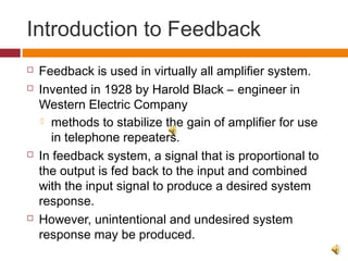
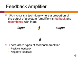
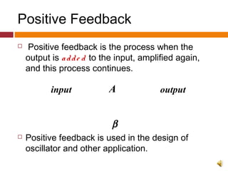
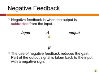
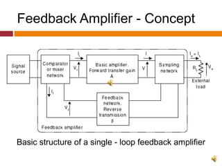
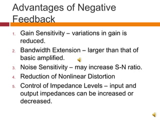
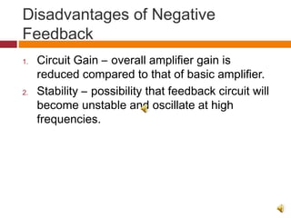
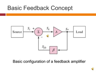
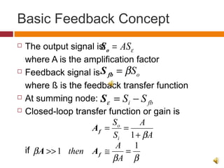
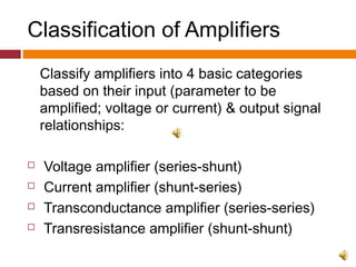
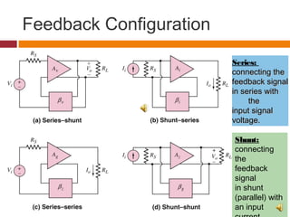
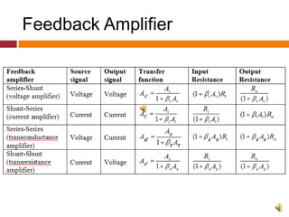
CHAPTER 2
FEEDBACK
AMPLIFIERS
ECE 205 – ELECTRONIC CIRCUITS
Outline
1. Introduction to Feedback
2. Feedback Amplifier – Positive & Negative
3. Advantages/Disadvantages of Negative
Feedback
4. Basic Feedback Concept
5. Classification of Amplifiers
6. Series – Shunt Configuration
7. Shunt – Series Configuration
8. Series - Series Configuration
9. Shunt – Shunt Configuration
Introduction to Feedback
 Feedback is used in virtually all amplifier system.
 Invented in 1928 by Harold Black – engineer in
Western Electric Company
 methods to stabilize the gain of amplifier for use
in telephone repeaters.
 In feedback system, a signal that is proportional to
the output is fed back to the input and combined
with the input signal to produce a desired system
response.
 However, unintentional and undesired system
response may be produced.
Feedback Amplifier
 Fe e dback is a technique where a proportion of
the output of a system (amplifier) is fed back and
recombined with input
 There are 2 types of feedback amplifier:
 Positive feedback
 Negative feedback
A
β
input output
Positive Feedback
 Positive feedback is the process when the
output is adde d to the input, amplified again,
and this process continues.
 Positive feedback is used in the design of
oscillator and other application.
A
β
input output
+
Positive Feedback - Example
 In a PA system
get feedback when you put the microphone in
front of a speaker and the sound gets
uncontrollably loud (you have probably heard
this unpleasant effect).
Negative Feedback
 Negative feedback is when the output is
subtracted from the input.
 The use of negative feedback reduces the gain.
Part of the output signal is taken back to the input
with a negative sign.
A
β
input output
Negative Feedback - Example
 Speed control
If the car starts to speed up above the desired
set-point speed, negative feedback causes the
throttle to close, thereby reducing speed;
similarly, if the car slows, negative feedback
acts to open the throttle
Feedback Amplifier - Concept
Basic structure of a single - loop feedback amplifier
Advantages of Negative
Feedback
1. Gain Sensitivity – variations in gain is
reduced.
2. Bandwidth Extension – larger than that of
basic amplified.
3. Noise Sensitivity – may increase S-N ratio.
4. Reduction of Nonlinear Distortion
5. Control of Impedance Levels – input and
output impedances can be increased or
decreased.
Disadvantages of Negative
Feedback
1. Circuit Gain – overall amplifier gain is
reduced compared to that of basic amplifier.
2. Stability – possibility that feedback circuit will
become unstable and oscillate at high
frequencies.
Basic Feedback Concept
Basic configuration of a feedback amplifier
Basic Feedback Concept
 The output signal is:
where A is the amplification factor
 Feedback signal is
where ß is the feedback transfer function
 At summing node:
 Closed-loop transfer function or gain is
if
εAS=oS
oSβ=fbS
fbi SS −=εS
A
A
S
S
i
o
β+
==
1
fA
ββ
β
1
1 =≅>>
A
A
then fAA
Classification of Amplifiers
Classify amplifiers into 4 basic categories
based on their input (parameter to be
amplified; voltage or current) & output signal
relationships:
 Voltage amplifier (series-shunt)
 Current amplifier (shunt-series)
 Transconductance amplifier (series-series)
 Transresistance amplifier (shunt-shunt)
Feedback Configuration
Series:
connecting theconnecting the
feedback signalfeedback signal
in series within series with
thethe
input signalinput signal
voltage.voltage.
Shunt:
connecting
the
feedback
signal
in shunt
(parallel) with
an input
Feedback Amplifier

feedback amplifier

  • 1.
  • 2.
    Outline 1. Introduction toFeedback 2. Feedback Amplifier – Positive & Negative 3. Advantages/Disadvantages of Negative Feedback 4. Basic Feedback Concept 5. Classification of Amplifiers 6. Series – Shunt Configuration 7. Shunt – Series Configuration 8. Series - Series Configuration 9. Shunt – Shunt Configuration
  • 3.
    Introduction to Feedback Feedback is used in virtually all amplifier system.  Invented in 1928 by Harold Black – engineer in Western Electric Company  methods to stabilize the gain of amplifier for use in telephone repeaters.  In feedback system, a signal that is proportional to the output is fed back to the input and combined with the input signal to produce a desired system response.  However, unintentional and undesired system response may be produced.
  • 4.
    Feedback Amplifier  Fee dback is a technique where a proportion of the output of a system (amplifier) is fed back and recombined with input  There are 2 types of feedback amplifier:  Positive feedback  Negative feedback A β input output
  • 5.
    Positive Feedback  Positivefeedback is the process when the output is adde d to the input, amplified again, and this process continues.  Positive feedback is used in the design of oscillator and other application. A β input output +
  • 6.
    Positive Feedback -Example  In a PA system get feedback when you put the microphone in front of a speaker and the sound gets uncontrollably loud (you have probably heard this unpleasant effect).
  • 7.
    Negative Feedback  Negativefeedback is when the output is subtracted from the input.  The use of negative feedback reduces the gain. Part of the output signal is taken back to the input with a negative sign. A β input output
  • 8.
    Negative Feedback -Example  Speed control If the car starts to speed up above the desired set-point speed, negative feedback causes the throttle to close, thereby reducing speed; similarly, if the car slows, negative feedback acts to open the throttle
  • 9.
    Feedback Amplifier -Concept Basic structure of a single - loop feedback amplifier
  • 10.
    Advantages of Negative Feedback 1.Gain Sensitivity – variations in gain is reduced. 2. Bandwidth Extension – larger than that of basic amplified. 3. Noise Sensitivity – may increase S-N ratio. 4. Reduction of Nonlinear Distortion 5. Control of Impedance Levels – input and output impedances can be increased or decreased.
  • 11.
    Disadvantages of Negative Feedback 1.Circuit Gain – overall amplifier gain is reduced compared to that of basic amplifier. 2. Stability – possibility that feedback circuit will become unstable and oscillate at high frequencies.
  • 12.
    Basic Feedback Concept Basicconfiguration of a feedback amplifier
  • 13.
    Basic Feedback Concept The output signal is: where A is the amplification factor  Feedback signal is where ß is the feedback transfer function  At summing node:  Closed-loop transfer function or gain is if εAS=oS oSβ=fbS fbi SS −=εS A A S S i o β+ == 1 fA ββ β 1 1 =≅>> A A then fAA
  • 14.
    Classification of Amplifiers Classifyamplifiers into 4 basic categories based on their input (parameter to be amplified; voltage or current) & output signal relationships:  Voltage amplifier (series-shunt)  Current amplifier (shunt-series)  Transconductance amplifier (series-series)  Transresistance amplifier (shunt-shunt)
  • 15.
    Feedback Configuration Series: connecting theconnectingthe feedback signalfeedback signal in series within series with thethe input signalinput signal voltage.voltage. Shunt: connecting the feedback signal in shunt (parallel) with an input
  • 16.