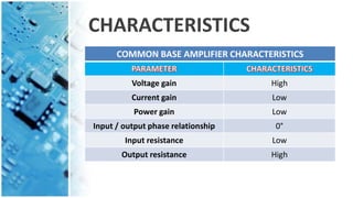
BASEBIASEDAMPLIFIER
PREPARED BY
Ketan nayak (140413117005)
Nirmal Gohil (140413117003)
INDEX
Sr No TITLE
1 Introduction
2 Types of Amplifier
3 COMMON BASE AMPLIFIER
4 Circuit Diagram
5 Operation of a Common Base Amplifier
6 Features of the Common Base Amplifier
7 Characteristics of Common Base Amplifier
8 Applications of the Common Base Amplifier
INTRODUCTION
• Amplifier:- An Amplifier, is an electronic
device that increase the power of a signal.
• It does this by taking energy from a power
supply and controlling the output to match
the input signal shape but with a larger
amplitude.
• In this sense, an amplifier modulates the
output of the power supply to make the
output signal stronger than the input signal.
TYPES OF AMPLIFIER
• There are Basically Four Types of Amplifier.
1. Voltage Amplifier
2. Current Amplifier
3. Transconductance
4. Transresistance
• Common Base, Common Emitter and
Common Collector are the Configurations
of the Amplifier.
COMMON BASE AMPLIFIER
• In electronics, a common base (also known as
grounded-base) amplifier is one of three basic
single-stage bipolar junction transistor (BJT)
amplifier topologies, typically used as a current
buffer or voltage amplifier.
• In this circuit the emitter terminal of the transistor
serves as the input, the collector the output, and
the base is connected to ground, or "common",
hence its name. The analogous field-effect transistor
circuit is the common gate amplifier.
CIRCUIT DIAGRAM
OPERATION
• In the Positive Half Cycle of Input Voltage Vs. Emitter
Voltage varies Sinusoidally above Q point value.
• Hence Vbe reduces. This will reduce Ib which in turn
reduces Ic .
• The Drop Across Rc .
i.e. IcRc will reduce and Collector Voltage Increase.
• Thus we get a Positive half cycle of Output Voltage
corresponding to Positive Half Cycle of Input Voltage
• Similarly we get a Negative Half Cycle at the Output
corresponding to the Negative half cycle at Input.
• Fig Shows the Input output Voltage Waveforms.
Note that there is no Phase shift between input and
Output of the Common Base Amplifier.
Features of Common Base Amplifier
1. Input Signal Vs is applied at Emitter and amplified
output is taken at the collector w.r.t Ground.
2. Base Terminal is Connected to Ground via
Capacitor C only for AC Signals.
3. Input resistance of this configuration is very low,
hence source loading can take place.
4. Output resistance is very Large.
5. Current Gain is approximately equal to 1, so no
Current amplification is there.
6. Voltage Gain is High.
CHARACTERISTICS
COMMON BASE AMPLIFIER CHARACTERISTICS
Voltage gain High
Current gain Low
Power gain Low
Input / output phase relationship 0°
Input resistance Low
Output resistance High
APPLICATIONS
• The Common Base Amplifiers are used for the
applications where impedance matching is to be
achieved. They are also used as Wideband
Amplifiers.
• i.e. The Amplifiers having Large Bandwidth.
Edc Base Biased Amplifier

Edc Base Biased Amplifier

  • 1.
    BASEBIASEDAMPLIFIER PREPARED BY Ketan nayak(140413117005) Nirmal Gohil (140413117003)
  • 2.
    INDEX Sr No TITLE 1Introduction 2 Types of Amplifier 3 COMMON BASE AMPLIFIER 4 Circuit Diagram 5 Operation of a Common Base Amplifier 6 Features of the Common Base Amplifier 7 Characteristics of Common Base Amplifier 8 Applications of the Common Base Amplifier
  • 3.
    INTRODUCTION • Amplifier:- AnAmplifier, is an electronic device that increase the power of a signal. • It does this by taking energy from a power supply and controlling the output to match the input signal shape but with a larger amplitude. • In this sense, an amplifier modulates the output of the power supply to make the output signal stronger than the input signal.
  • 4.
    TYPES OF AMPLIFIER •There are Basically Four Types of Amplifier. 1. Voltage Amplifier 2. Current Amplifier 3. Transconductance 4. Transresistance • Common Base, Common Emitter and Common Collector are the Configurations of the Amplifier.
  • 5.
    COMMON BASE AMPLIFIER •In electronics, a common base (also known as grounded-base) amplifier is one of three basic single-stage bipolar junction transistor (BJT) amplifier topologies, typically used as a current buffer or voltage amplifier. • In this circuit the emitter terminal of the transistor serves as the input, the collector the output, and the base is connected to ground, or "common", hence its name. The analogous field-effect transistor circuit is the common gate amplifier.
  • 6.
  • 7.
    OPERATION • In thePositive Half Cycle of Input Voltage Vs. Emitter Voltage varies Sinusoidally above Q point value. • Hence Vbe reduces. This will reduce Ib which in turn reduces Ic . • The Drop Across Rc . i.e. IcRc will reduce and Collector Voltage Increase. • Thus we get a Positive half cycle of Output Voltage corresponding to Positive Half Cycle of Input Voltage
  • 8.
    • Similarly weget a Negative Half Cycle at the Output corresponding to the Negative half cycle at Input. • Fig Shows the Input output Voltage Waveforms. Note that there is no Phase shift between input and Output of the Common Base Amplifier.
  • 9.
    Features of CommonBase Amplifier 1. Input Signal Vs is applied at Emitter and amplified output is taken at the collector w.r.t Ground. 2. Base Terminal is Connected to Ground via Capacitor C only for AC Signals. 3. Input resistance of this configuration is very low, hence source loading can take place. 4. Output resistance is very Large. 5. Current Gain is approximately equal to 1, so no Current amplification is there. 6. Voltage Gain is High.
  • 10.
    CHARACTERISTICS COMMON BASE AMPLIFIERCHARACTERISTICS Voltage gain High Current gain Low Power gain Low Input / output phase relationship 0° Input resistance Low Output resistance High
  • 11.
    APPLICATIONS • The CommonBase Amplifiers are used for the applications where impedance matching is to be achieved. They are also used as Wideband Amplifiers. • i.e. The Amplifiers having Large Bandwidth.