This application note explores transients and overvoltages in AC power systems, focusing on surge protection and mitigation techniques. It discusses the functionality and types of surge protective devices (SPDs), their performance under surges and steady-state variations, along with various mitigation strategies for capacitor-switching transients. The note emphasizes the importance of proper SPD selection and installation to ensure effective protection against electrical surges.


![Publication No Cu0141
Issue Date: August 2015
Page 2
FUNDAMENTALS OF SURGE PROTECTION
GENERAL
In the low-voltage (end-user) environment, SPDs serve to divert impinging surges by offering a low-impedance
path to return the surge current to its source. This function can be accomplished in a single or several stages,
depending on the system configuration and the degree of freedom available to the user in connecting SPDs at
different points of the system.
Large surges originating outside of the user's facility – usually associated with lightning or major power-system
events – are best diverted at the service entrance of a facility. Surges generated within the premises can be
diverted by SPDs located close to the internal surge source or close to the sensitive equipment in need of
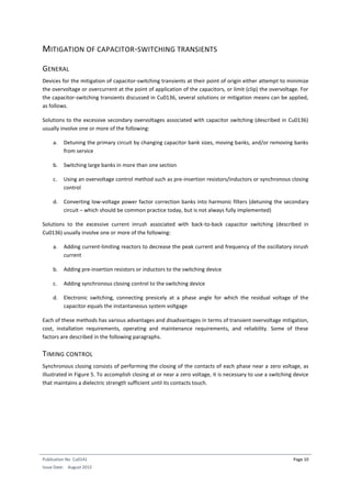
protection. Figure 1 shows the principle of a two-stage protection scheme. The first stage provides diversion of
impinging high-energy surges
*
through the arrester, typically installed at the service entrance, or by a device
permanently connected at the service panel. Some restriction of the propagation of surge currents in branch
circuits is inherently provided by the inductance of the premises wiring. The second stage of voltage limiting is
provided by an SPD of lesser surge-handling capability which is typically located close to the equipment in
need of protection as an add-on, plug-in device, or incorporated within the equipment by the manufacturer.
This second stage completes the scheme for dealing with surges of external origin as well as for surges
originating within the building.
Figure 1 – A two stage protection scheme.
*
The term high-energy surge is used here as short-hand for the more accurate term surge with high energy-
delivery capability. Some power-quality surveys reports make reference to the concept of and term energy in
the surge as an abstract characteristic of the surge itself, which could be derived from measuring only the
voltage and duration of a surge occurring in the power system Such characterization is meaningless and
misleading (Standler, 1989); (Key et al., 1996].](https://image.slidesharecdn.com/cu0141antransientsandovervmitigationv2-190712170451/85/Transient-overvoltages-and-currents-mitigation-and-protection-techniques-5-320.jpg)

![Publication No Cu0141
Issue Date: August 2015
Page 7
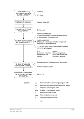
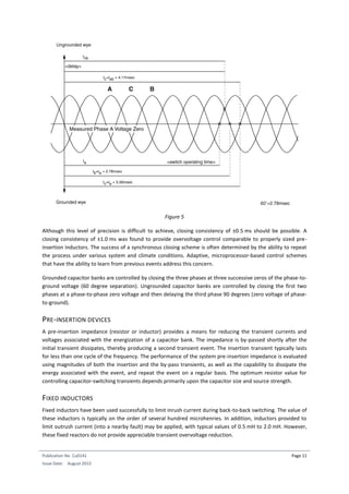
SELECTION OF LIMITING LEVELS
Under the perception that it is necessary – or at least desirable – to provide the lowest possible level for the
limiting (clamping) voltage, some SPD manufacturers have been offering SPDs with a limiting level as low as
330 V for 120 V circuits. These manufacturers claim superior performance over competing SPDs that achieve
somewhat higher levels (such as 400 V or 500 V) under the same specified applied surge current. A similar
downward auction for limiting voltage selection is likely to occur for other system voltages.
During the development of the seminal standard UL 1449 and IEC Publication 664 in the late seventies and
early eighties, a table of overvoltage categories was under consideration with levels that included the 330 V
value. However, it is noteworthy that this level was not cited in IEC 664 as a level for systems rated at 120 V,
but rather as a level for systems rated at 50 V. Thus, the understandable desirability of effective protection
through low limiting voltage became biased toward considering (advertising) a limiting voltage of 330 V as a
plus factor in evaluating the performance of SPDs for 120 V circuit applications.
A better perspective of the issue was reached in the nineties, but the outmoded perceptions and advertising
claims linger. Against these, the following facts and considerations should be kept in mind:
- Among published papers on immunity testing of appliances [Anderson & Bowes, 1990, Smith &
Standler, 1992], and surge immunity tests performed on a wide range of appliances, no adverse
effects have been reported until the applied surges exceed thresholds of 600 V to 1,000 V
- The well-accepted CBEMA Curve (now renamed ITIC Curve) did not require limiting voltages of 330 V
(for 120 V loads) for durations of less than 0.5 ms, and allowed limiting voltages with increasing levels
at shorter durations
- A low limiting level can result in premature aging of the SPD when it is called upon to more frequently
clamp surges that would not have caused any intervention of an SPD with somewhat higher limiting
voltage [Martzloff & Leedy, 1989], or swells resulting in significant shift of the nominal voltage when
applied in large numbers over the life of the device [Lagergren et al., 1992]
- Some utilities wish to select an SPD capable of withstanding twice the line-to-neutral voltage in order
to avoid device failure or fuse opening under the condition of lost neutral connection
It appears then that the advantage of a low limiting voltage can in fact have undesirable side effects on the
long-term overall reliability of the application of an SPD in end-user circuits. The chart in Figure 4 summarizes
the considerations involved in selecting a suitable SPD. Clearly, the mere selection of a limiting level as a
retrofit approach to protect a piece of equipment is insufficient for a reliable application.](https://image.slidesharecdn.com/cu0141antransientsandovervmitigationv2-190712170451/85/Transient-overvoltages-and-currents-mitigation-and-protection-techniques-10-320.jpg)

![Publication No Cu0141
Issue Date: August 2015
Page 12
After all, the presence of a reactor connected in series with a compensation capacitor should be common
practice today. Such a combination will act as a detuning reactor to avoid resonances between the
compensation capacitance and any inherent inductance in the system. Such resonances could be excited by
lower order harmonics present in the system. The inductance ratings of such detuning reactors, however, are
one or two orders of magnitudes higher than of those for mitigating the inrush currents. Consequently, the
current transient when connecting a capacitance is replaced by a voltage transient when disconnecting an
inductance. This needs to be dealt with accordingly.
MOV ARRESTERS
Metal oxide varistors (MOVs) can limit transient overvoltages to the protective level (typically 1.8 to 2.5 per-
unit) at the point of application. The primary concern associated with MOV application is the energy duty
during a restrike event. Although a rare occurrence, a switch restrike generally results in the highest arrester
duty for arresters located at the switched capacitor. In addition, remote arresters (including low-voltage
customer applications) can be subjected to severe energy duty if voltage magnification occurs. This condition
could be especially troublesome for distribution systems if SiC-based arresters remain in service.
The effectiveness of these mitigation methods is system dependent, and a detailed analysis is necessary to
select the optimum scheme [Mikhail et al., 1986]; [Grebe, 1995]. While often justifiable for large transmission
applications, transient analysis of distribution capacitor applications is rarely performed and, in general,
capacitor banks are installed without transient overvoltage control.
If these preventive measures against capacitor switching transients are not practical or possible for an end-
user customer to coordinate with the supplier, then remedial measures can be applied at the service entrance
and points of connection of equipment in the customer's facility. This is described in the subchapter Function
of SPDs.](https://image.slidesharecdn.com/cu0141antransientsandovervmitigationv2-190712170451/85/Transient-overvoltages-and-currents-mitigation-and-protection-techniques-15-320.jpg)
![Publication No Cu0141
Issue Date: August 2015
Page 15
Figure 6
Coordination between two SPDs can be demonstrated by five different approaches, described below.
Whatever the approach, it is necessary that the end-user have control over the selection of the SPDs,
preferably both of them. If one is already given and beyond the control of the end-user, the coordination of
the second candidate SPD can be assessed and more suitable candidates identified if necessary. Most of the
time, coordination is, or might seem to be a complex situation. Some of the following five procedures might
then appear to the end-user as difficult to apply, due to lack of knowledge concerning some data, as for
example accurate SPD characteristics. Nevertheless, coordination is necessary to ensure technically effective
and cost-effective use of resources.
ASSESSMENT OF COORDINATION
The five basic different methods of assessing the coordination of two SPDs are:
1. Application of preferred SPD combinations. This is the most convenient variant for the users because
the burden of demonstration is incumbent upon the SPD manufacturer. However, this approach
implies either that a sole source manufacturer be selected, or that standard methods be developed to
allow determination that candidate devices from different sources are in fact equivalent.
2. Coordination computation. Computer simulation enables complex systems to be examined and
parametric evaluation performed over a wide range.
3. Application of the Let-Through Energy concept. In this concept, some decoupling impedance is
postulated in the upstream SPD and a computation is performed for converting the SPD
characteristics on the basis of an equivalent combination wave generator. A comparison can then be
made with the energy-withstand capability of the downstream SPD (Hasse et al., 1994]
4. Coordination test. A full-scale test is performed with candidate SPDs, for a postulated decoupling
impedance and a range of surge currents such that blind spots, if any, are revealed. Candidate devices
may include voltage-limiting SPDs, voltage-switching SPDs, or combination type SPD [voltage-
switching SPD + voltage-limiting SPD].
5. Simplified rules with margin. Simplified tables including margins for the coordination of some typical
SPDs may be used when no other data is known from the SPD manufacturers. The values given in
these tables include sufficient margins to cover discrepancies between manufacturers and
manufacturing tolerances.](https://image.slidesharecdn.com/cu0141antransientsandovervmitigationv2-190712170451/85/Transient-overvoltages-and-currents-mitigation-and-protection-techniques-18-320.jpg)
![Publication No Cu0141
Issue Date: August 2015
Page 16
SYSTEM INTERACTION PROTECTION
As discussed in Cu0138, interactions at equipment ports involving different systems can produce damaging or
upsetting shifts in reference potentials during surge events. Anecdotal information indicates that this
mechanism is probably the most frequent cause of electronic consumer equipment failure (TV receivers and
VCRs with cable signal input, computers with wired modem connection, smart telephones, etc.)
Various mitigation schemes have been proposed to remedy upsetting or damaging potential differences.
Increasing the withstand capability of the PC system by the manufacturers is unlikely to occur, given the
market economics. Moreover, it actually might not be practical for some of the voltages that can appear in
actual situations. The most effective course would be a fibre optic decoupling, inserted in the communications
link, but the expense and involvement required would be objectionable for the typical home office application.
For industrial applications where the consequences can be severe, this approach is often selected and has
been found to be both successful and cost-effective
NON-METALLIC LINKS
Consumer options are limited to either replacement of existing conducted communication and control links
with their fibre optic counterparts, or insertion of commercially available isolation devices as needed. The first
option, while appropriate for new installations, might not be cost-effective for an existing installation. Devices
manufactured specifically for various port types can be applied for existing installations. For example, RS-232
communications are often used for connecting programmable logic controllers and other devices in utility and
industrial facilities. These links are easily isolated using an optically coupled adapter that connects directly to
the RS-232 port. These devices must have a suitable voltage isolation rating (e.g. kilovolts) for the application.
Some of these devices only have isolation capability measured in hundreds of volts which might not be
sufficient. Similar devices exist for other ports.
EQUALIZING REFERENCE POTENTIALS
Theoretically, a simple way to eliminate the shifts in reference potentials during surge events would be to
bond the two reference conductors of the two systems. However, such a simple bonding might not be
acceptable from the point of view of the system operators, the local or national codes, and product listing
agencies. Therefore, this Guide cannot provide recommendations applicable to all situations in all countries,
but only describe general principles leading to a solution.
When bonding the two references directly is not permitted, it might be permissible to provide an SPD of
appropriate characteristics that will in effect bond the two references – although with some potential
difference still left – but only during a surge event. This legitimately circumvents the prohibition of a
permanent bonding under steady-state conditions. The alternative, i.e. no bond at all, is that unintended
bonding is likely to occur – with damaging results – by sparkover of the clearances separating the conductors
of the two systems. For instance, tests have shown that the isolation between the cable input and the tuner of
a typical TV receiver will flashover at about 2.5 kV [Martzloff, 2000].](https://image.slidesharecdn.com/cu0141antransientsandovervmitigationv2-190712170451/85/Transient-overvoltages-and-currents-mitigation-and-protection-techniques-19-320.jpg)