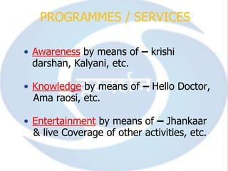
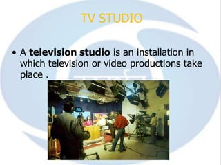
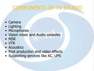
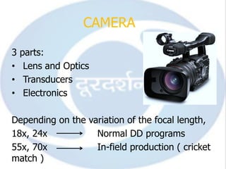
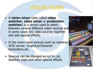
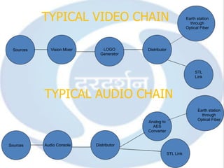
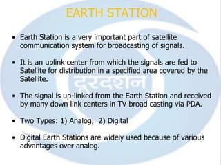
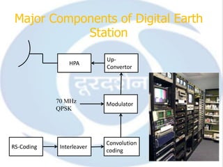
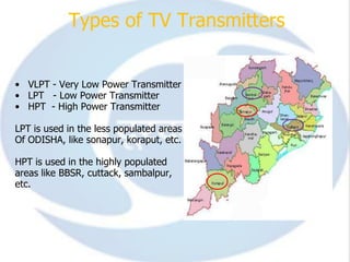
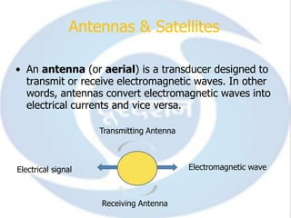
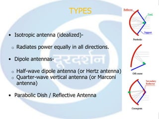
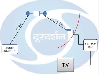
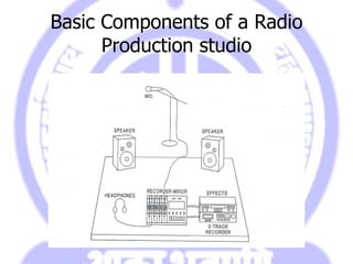
IN-PLANT TRAINING


          SUBMITTED BY:
          NIBEDAN BHAWSINKA
          09BEC039
          BTECH-ECE
PROGRAMMES / SERVICES

• Awareness by means of – krishi
  darshan, Kalyani, etc.

• Knowledge by means of – Hello Doctor,
  Ama raosi, etc.

• Entertainment by means of – Jhankaar
  & live Coverage of other activities, etc.
CONTENTS

•   INTRODUCTION
•   TV STUDIO
•   VISION MIXER
•   AUDIO/ VIDEO CHAINS
•   MSR
•   EARTH STATION
•   TV Tx
•   ANTENNAS & SATELLITES
INTRODUCTION

To Broadcasting
• A process of sending information to a distant
  place is called Broadcasting.

• Means of Broadcasting in India:
 1. Terrestrial
 2. Satellite
 3. Internet
• Both AIR & DD make use of both Terrestrial &
  satellite.
For Indian footprint, suitable range of slots is
              45 deg to 110 deg.

Earlier, available slots       : 74, 83, 95 deg
After, ISRO got additional slots: 48, 55, 111.5
deg
Basic Principal:

Signal from earth station of one channel
should not affect the broadcasting of other
channels.
cont...
  • DD national has 1500 Transmitters and 70
    Production centers across the Country.

  • These centers are divided in 3 levels-

1. -National centers
2. -Regional centers
3. -Local centers

  • transmission started on 20th sep. 1987.
TV STUDIO

• A television studio is an installation in
  which television or video productions take
  place .
COMPONENTS OF TV STUDIO

•   Camera
•   Lighting
•   Microphones
•   Vision mixer and Audio consoles
•   MSR
•   VTR
•   Acoustics
•   Post production and video effects
•   Supporting services like AC, UPS
CAMERA

3   parts:
•    Lens and Optics
•    Transducers
•    Electronics

Depending on the variation of the focal length,
18x, 24x           Normal DD programs
55x, 70x           In-field production ( cricket
match )
2 filters used:
• ND filter- To neutralize the density, i.e. it
    reduces the light intensity.
     - ND-1: 15%
     - ND-2: 30%
     - ND-3: 50%
• CC filter- Color correction
      4 modes:
1. F1- 3200K (in studio- gives a partial orange
    light)
2. F2- 4600K (cloudy weather)
3. F3- 5600K (outdoor/sunny)
4. F4- Opaque
VISION MIXER
• A vision mixer (also called video
  switcher, video mixer or production
  switcher) is a device used to select
  between several different video sources and
  in some cases mix video sources together
  and add special effects.

• It has many input sources such as cameras,
  VCR/ server, Graphics/Character
  Generators,etc.

• Sources can be changed as cut to cut,
  dissolve, wipe and other special effects.
SOUND WAVES


Source
                              SOUND WAVE
  of
Sound


                   MOLECULES
Region of High Pressure (Compression) and
Region of low pressure (Rarefaction)
Audio Compression


100 dB


  0 dB


            1 KHz
                             Threshold of silence
Compression is done by removing the
components in threshold of silence , thus
removing some redundancy.

This is done by :
• MASKING
• SUB-BAND CODING
• TRANSFORM CODING

MP3( MPEG-1 LAYER 3) uses both sub-band
and transform coding.
TYPICAL VIDEO CHAIN                                      Earth station
                                                                      through
                                                                    Optical Fiber


 Sources      Vision Mixer      LOGO       Distributor
                               Generator


                                                                         STL
                                                                         Link


           TYPICAL AUDIO CHAIN
                                                                          Earth station
                                                                            through
                                                                          Optical Fiber
                                           Analog to
                                             AES
                                           Converter


Sources    Audio Console     Distributor

                                                         STL Link
MSR

• It is the heart of the studio.

• Most of the switching electronics is
  kept e.g. camera base stations,
  switcher main frame, SPG, Satellite
  receivers, MW link, DDA & most of
  the patch panels.

• Signal is routed through MSR.

• Signal can be Monitored at various
  stages
EARTH STATION
• Earth Station is a very important part of satellite
  communication system for broadcasting of signals.

• It is an uplink center from which the signals are fed to
  Satellite for distribution in a specified area covered by the
  Satellite.

• The signal is up-linked from the Earth Station and received
  by many down link centers in TV broad casting via PDA.

• Two Types: 1) Analog, 2) Digital

• Digital Earth Stations are widely used because of various
  advantages over analog.
R
                  270Mbps
G                            QPSK

B


                                         135 Mbps


    Video
                            3- 15 Mbps
    Audio   ENCODER
                            Normal - 5 Mbps
                            Sports - 7 Mbps
                            News - 3-3.5 Mbps
Major Components of Digital Earth
            Station
                           Up-
                HPA
                           Convertor


            70 MHz         Modulator
            QPSK


                           Convolution
RS-Coding    Interleaver
                           coding
Types of TV Transmitters


• VLPT - Very Low Power Transmitter
• LPT - Low Power Transmitter
• HPT - High Power Transmitter

LPT is used in the less populated areas
Of ODISHA, like sonapur, koraput, etc.

HPT is used in the highly populated
areas like BBSR, cuttack, sambalpur,
etc.
Antennas & Satellites

• An antenna (or aerial) is a transducer designed to
  transmit or receive electromagnetic waves. In other
  words, antennas convert electromagnetic waves into
  electrical currents and vice versa.

                    Transmitting Antenna


Electrical signal                          Electromagnetic wave


                    Receiving Antenna
TYPES

• Isotropic antenna (idealized)-

 o   Radiates power equally in all directions.

• Dipole antennas-

 o   Half-wave dipole antenna (or Hertz antenna)
 o   Quarter-wave vertical antenna (or Marconi
     antenna)

• Parabolic Dish / Reflective Antenna
SET-TOP
 EARTH            BOX
   `
STATION


          T.V
Uplink Frequency : 6 GHz
Downlink Frequency: 4 GHz

Uplink frequency is greater than downlink
frequency coz we need narrow beam to
reach the satellite and a wider footprint
while downlink.

LNBC: It amplifies the received signal before
sending it to the set-top box.
Scalable video

    Decode according to
    required QoS or
    available hardware resources.


                 Encode
                 once


Quality ~ deployed hardware resources
ALL INDIA RADIO


   HPA

         6 GHz

  Up-
Convertor


    FM         70 MHz (IF)


Audio Signal
Basic Components of a Radio
      Production studio
Thank You
   

Doorsdarshan and All India Radio Summer Training

  • 1.
    IN-PLANT TRAINING SUBMITTED BY: NIBEDAN BHAWSINKA 09BEC039 BTECH-ECE
  • 2.
    PROGRAMMES / SERVICES •Awareness by means of – krishi darshan, Kalyani, etc. • Knowledge by means of – Hello Doctor, Ama raosi, etc. • Entertainment by means of – Jhankaar & live Coverage of other activities, etc.
  • 3.
    CONTENTS • INTRODUCTION • TV STUDIO • VISION MIXER • AUDIO/ VIDEO CHAINS • MSR • EARTH STATION • TV Tx • ANTENNAS & SATELLITES
  • 4.
    INTRODUCTION To Broadcasting • Aprocess of sending information to a distant place is called Broadcasting. • Means of Broadcasting in India: 1. Terrestrial 2. Satellite 3. Internet • Both AIR & DD make use of both Terrestrial & satellite.
  • 5.
    For Indian footprint,suitable range of slots is 45 deg to 110 deg. Earlier, available slots : 74, 83, 95 deg After, ISRO got additional slots: 48, 55, 111.5 deg Basic Principal: Signal from earth station of one channel should not affect the broadcasting of other channels.
  • 6.
    cont... •DD national has 1500 Transmitters and 70 Production centers across the Country. • These centers are divided in 3 levels- 1. -National centers 2. -Regional centers 3. -Local centers • transmission started on 20th sep. 1987.
  • 7.
    TV STUDIO • Atelevision studio is an installation in which television or video productions take place .
  • 8.
    COMPONENTS OF TVSTUDIO • Camera • Lighting • Microphones • Vision mixer and Audio consoles • MSR • VTR • Acoustics • Post production and video effects • Supporting services like AC, UPS
  • 9.
    CAMERA 3 parts: • Lens and Optics • Transducers • Electronics Depending on the variation of the focal length, 18x, 24x Normal DD programs 55x, 70x In-field production ( cricket match )
  • 10.
    2 filters used: •ND filter- To neutralize the density, i.e. it reduces the light intensity. - ND-1: 15% - ND-2: 30% - ND-3: 50% • CC filter- Color correction 4 modes: 1. F1- 3200K (in studio- gives a partial orange light) 2. F2- 4600K (cloudy weather) 3. F3- 5600K (outdoor/sunny) 4. F4- Opaque
  • 11.
    VISION MIXER • Avision mixer (also called video switcher, video mixer or production switcher) is a device used to select between several different video sources and in some cases mix video sources together and add special effects. • It has many input sources such as cameras, VCR/ server, Graphics/Character Generators,etc. • Sources can be changed as cut to cut, dissolve, wipe and other special effects.
  • 13.
    SOUND WAVES Source SOUND WAVE of Sound MOLECULES Region of High Pressure (Compression) and Region of low pressure (Rarefaction)
  • 14.
    Audio Compression 100 dB 0 dB 1 KHz Threshold of silence
  • 15.
    Compression is doneby removing the components in threshold of silence , thus removing some redundancy. This is done by : • MASKING • SUB-BAND CODING • TRANSFORM CODING MP3( MPEG-1 LAYER 3) uses both sub-band and transform coding.
  • 17.
    TYPICAL VIDEO CHAIN Earth station through Optical Fiber Sources Vision Mixer LOGO Distributor Generator STL Link TYPICAL AUDIO CHAIN Earth station through Optical Fiber Analog to AES Converter Sources Audio Console Distributor STL Link
  • 18.
    MSR • It isthe heart of the studio. • Most of the switching electronics is kept e.g. camera base stations, switcher main frame, SPG, Satellite receivers, MW link, DDA & most of the patch panels. • Signal is routed through MSR. • Signal can be Monitored at various stages
  • 19.
    EARTH STATION • EarthStation is a very important part of satellite communication system for broadcasting of signals. • It is an uplink center from which the signals are fed to Satellite for distribution in a specified area covered by the Satellite. • The signal is up-linked from the Earth Station and received by many down link centers in TV broad casting via PDA. • Two Types: 1) Analog, 2) Digital • Digital Earth Stations are widely used because of various advantages over analog.
  • 20.
    R 270Mbps G QPSK B 135 Mbps Video 3- 15 Mbps Audio ENCODER Normal - 5 Mbps Sports - 7 Mbps News - 3-3.5 Mbps
  • 21.
    Major Components ofDigital Earth Station Up- HPA Convertor 70 MHz Modulator QPSK Convolution RS-Coding Interleaver coding
  • 22.
    Types of TVTransmitters • VLPT - Very Low Power Transmitter • LPT - Low Power Transmitter • HPT - High Power Transmitter LPT is used in the less populated areas Of ODISHA, like sonapur, koraput, etc. HPT is used in the highly populated areas like BBSR, cuttack, sambalpur, etc.
  • 23.
    Antennas & Satellites •An antenna (or aerial) is a transducer designed to transmit or receive electromagnetic waves. In other words, antennas convert electromagnetic waves into electrical currents and vice versa. Transmitting Antenna Electrical signal Electromagnetic wave Receiving Antenna
  • 24.
    TYPES • Isotropic antenna(idealized)- o Radiates power equally in all directions. • Dipole antennas- o Half-wave dipole antenna (or Hertz antenna) o Quarter-wave vertical antenna (or Marconi antenna) • Parabolic Dish / Reflective Antenna
  • 25.
    SET-TOP EARTH BOX ` STATION T.V
  • 26.
    Uplink Frequency :6 GHz Downlink Frequency: 4 GHz Uplink frequency is greater than downlink frequency coz we need narrow beam to reach the satellite and a wider footprint while downlink. LNBC: It amplifies the received signal before sending it to the set-top box.
  • 27.
    Scalable video Decode according to required QoS or available hardware resources. Encode once Quality ~ deployed hardware resources
  • 28.
    ALL INDIA RADIO HPA 6 GHz Up- Convertor FM 70 MHz (IF) Audio Signal
  • 29.
    Basic Components ofa Radio Production studio
  • 30.