A Broadcast Engineering Tutorial for Non Engineers Third Edition Graham A. Jones
A Broadcast Engineering Tutorial for Non Engineers Third Edition Graham A. Jones
A Broadcast Engineering Tutorial for Non Engineers Third Edition Graham A. Jones
A Broadcast Engineering Tutorial for Non Engineers Third Edition Graham A. Jones
A Broadcast Engineering Tutorial for Non Engineers Third Edition Graham A. Jones
1.
Visit https://ebookultra.com todownload the full version and
explore more ebooks
A Broadcast Engineering Tutorial for Non
Engineers Third Edition Graham A. Jones
_____ Click the link below to download _____
https://ebookultra.com/download/a-broadcast-
engineering-tutorial-for-non-engineers-third-edition-
graham-a-jones/
Explore and download more ebooks at ebookultra.com
2.
Here are somesuggested products you might be interested in.
Click the link to download
Introduction to Communications Technologies A Guide for
Non Engineers 1st Edition Stephan Jones
https://ebookultra.com/download/introduction-to-communications-
technologies-a-guide-for-non-engineers-1st-edition-stephan-jones/
Accounting for Non accountants A Manual for Managers and
Students 6th Edition Graham Mott
https://ebookultra.com/download/accounting-for-non-accountants-a-
manual-for-managers-and-students-6th-edition-graham-mott/
Continuum Mechanics for Engineers Third Edition G. Thomas
Mase
https://ebookultra.com/download/continuum-mechanics-for-engineers-
third-edition-g-thomas-mase/
Science for Engineering Third Edition John Bird
https://ebookultra.com/download/science-for-engineering-third-edition-
john-bird/
3.
Applied Statistics andProbability for Engineers Third
Edition Douglas C. Montgomery
https://ebookultra.com/download/applied-statistics-and-probability-
for-engineers-third-edition-douglas-c-montgomery/
Probabilistic Machine Learning for Civil Engineers James-A
Goulet
https://ebookultra.com/download/probabilistic-machine-learning-for-
civil-engineers-james-a-goulet/
Practical Guide to ICP MS A Tutorial for Beginners 2nd
Edition Robert Thomas
https://ebookultra.com/download/practical-guide-to-icp-ms-a-tutorial-
for-beginners-2nd-edition-robert-thomas/
Engineering strategies for greenhouse gas mitigation 1st
Edition Ian Jones
https://ebookultra.com/download/engineering-strategies-for-greenhouse-
gas-mitigation-1st-edition-ian-jones/
Human Factors for Highway Engineers 1st Edition J. A.
Santos
https://ebookultra.com/download/human-factors-for-highway-
engineers-1st-edition-j-a-santos/
5.
A Broadcast EngineeringTutorial for Non Engineers
Third Edition Graham A. Jones Digital Instant Download
Author(s): GrahamA. Jones
ISBN(s): 9780240807003, 0240807006
Edition: 3
File Details: PDF, 3.09 MB
Year: 2005
Language: english
A Broadcast EngineeringTutorial
for Non-Engineers
THIRD EDITION
Graham Jones
National Association of Broadcasters
AMSTERDAM • BOSTON • HEIDELBERG
LONDON • NEW YORK • OXFORD • PARIS
SAN DIEGO • SAN FRANCISCO • SINGAPORE
SYDNEY • TOKYO
Focal Press is an imprint of Elsevier
Contents
Preface xi
Acknowledgments xiii
1Introduction 1
BROADCASTING BASICS 3
2 Types of Broadcasting 5
Analog Radio 5
Digital Radio 6
Satellite Radio 8
Analog Television 9
Digital Television 10
Satellite Television 11
Cable Television 12
Groups and Networks 13
Internet Radio and Television 14
3 Sound and Vision 17
Sound and Audio 17
Light and Video 20
Baseband 22
4 Radio Frequency Waves 23
Electromagnetic Waves 23
Frequencies, Bands, and Channels 25
RF Over Wires and Cables 26
Modulation 27
v
12.
5 Analog ColorTelevision 33
NTSC 33
PAL and SECAM 42
HD Analog Video 43
6 Digital Audio and Video 45
Digital Audio 45
SD and HD Digital Video 52
7 Information Technology 61
Binary 61
Computers 63
Storage 65
Computer Networks 68
Internet Streaming 70
STUDIOS AND PRODUCTION FACILITIES 75
8 Radio Studios 77
Types of Studios 77
Studio Operations 78
System Considerations 81
Audio Mixing Consoles 84
Microphones 87
Loudspeakers and Headphones 89
CD Players 91
Hard Disk Recorders and Audio Workstations 92
Radio Program Automation 95
Digital Record/Playback Devices 96
Analog Devices 98
Telephone Hybrids 100
Remote Sources 101
Audio Delay Units 101
Emergency Alert System 102
Audio Processing Equipment 103
Signal Distribution 109
Ancillary Systems 111
Radio Master Control 112
Other Considerations and Capabilities 113
vi CONTENTS
13.
9 Television Studios117
Station and Network Operations 117
Types of Studios 119
Studio Lighting 121
Studio Control Rooms 122
System Considerations 123
Studio System 125
Video Switchers and Effects Units 127
Picture and Waveform Monitoring 130
Television Cameras 132
Film in Television 137
Videotape Recorders 140
Analog VTRs 144
Digital VTRs 145
HD Digital VTRs 149
Optical, Solid-State, and Hard Disk Recorders 151
Video Editing 152
SMPTE Timecode 153
Video Servers 154
Nonlinear Editing 156
Character Generators and Computer Graphics 158
Electronic Newsroom 159
Signal Distribution 159
Video Timing 162
Audio for Television 163
Ancillary Systems 166
Ingest and Conversion 167
Television Master Control 169
Television Automation 174
ATSC Encoding 176
Multicasting Operations 177
Closed Captioning Equipment 177
PSIP Generator 178
Data Broadcasting Equipment 178
Bitstream Distribution and Splicing 178
Internet Streaming 180
10 Remote Broadcasting 181
Radio News Gathering 181
Radio Remote Production 183
CONTENTS vii
14.
Television News Gathering183
Television Remote Production 186
11 Links 191
Contribution Links for Radio 191
Contribution Links for Television 193
Network Distribution Links for Radio and Television 195
Studio-Transmitter Links for Radio and Television 196
Analog and Digital Systems 199
TRANSMISSION STANDARDS
AND SYSTEMS 201
12 Analog Radio 203
AM Transmission 204
Emissions Masks 205
FM Transmission 206
Stereo Coding 208
Subcarriers 211
Radio Data System 212
13 IBOC Digital Radio 213
Phased IBOC Introduction 214
Carriers and Channels for IBOC 215
Modulation and Forward Error Correction 215
Audio Compression 216
AM IBOC 216
FM IBOC 218
Digital Radio Data Broadcasting 220
14 NTSC Analog Television 223
Carriers and Channels for Analog TV 223
Video Signal 224
Audio Signal 226
Vertical Blanking Interval Ancillary Information 227
Closed Captioning and Content Advisory Ratings 227
Analog TV Data Broadcasting 228
viii CONTENTS
15.
15 ATSC DigitalTelevision 231
Carriers and Channels for DTV 232
8-VSB Modulation 233
ATSC Compressed Bitstream 235
ATSC Video Formats 236
MPEG-2 Compression 238
AC-3 Audio 245
Multiplexing 249
Quality and Bit Rates 250
Multicasting 252
Closed Captions 253
Program and System Information Protocol (PSIP) 254
DTV Data Broadcasting 256
16 Transmitter Site Facilities 261
Incoming Feeds 262
Processing Equipment 263
Exciters 264
Power Amplifiers 266
Transmission Lines and Other Equipment 269
AM Antenna Systems 271
FM and TV Antennas 275
Towers 278
Translators and Repeaters 279
Transmitter Remote Control 280
17 Radio Wave Propagation and the FCC Rules 283
FCC Rules 283
AM Propagation 284
FM Propagation 286
IBOC Considerations 289
TV VHF and UHF Propagation 290
ATSC DTV Considerations 290
18 Conclusion 293
Further Information 293
Index 295
CONTENTS ix
17.
Preface
There are manypeople without engineering backgrounds who
need to have a general understanding of broadcast engineering
principles. They may be broadcast managers, program producers,
or other professionals who deal with broadcast clients. This tuto-
rial is intended to help non-engineers who want to learn something
about the technicalities of radio and television. It should also be
useful for engineers in training, or those in technical occupations
who want an overview of areas outside their area of expertise. We
explain the jargon of broadcasting and describe the underlying
principles, standards, and equipment for broadcast facilities, in
terms a layperson can understand.
The third edition has been completely revised to reflect the increas-
ing use of digital techniques in all aspects of television and radio
broadcasting. It has been reorganized and some obsolete material
removed, while also updating the basic information on traditional
analog technologies. New chapters have been added to provide an
overview of first principles and current standards in the broadcast
industry. We concentrate on over-the-air broadcasting from U.S.
radio and television stations, but also mention some of the other
methods of program delivery to the home and outline some of the
different standards and technologies used in other countries.
Although later chapters build on information in earlier sections,
this book can be consulted for information about a particular topic.
We hope that the information in these pages will help readers
further their understanding of our trade, and thus enhance their
ability to perform the broadcast-related functions of their jobs.
NAB Science and Technology Department
xi
19.
Acknowledgments
As the principalauthor and editor of the third edition of this tuto-
rial, I would like to acknowledge the contributions I have received
in preparing the book. The foundation, of course, was the second
edition, which came from NAB Science and Technology, although
very little of that work remains unchanged. I have received advice
and support from my colleagues at NAB: Art Allison, Janet Elliott,
David Layer, John Marino, and Kelly Williams, and from the Senior
Vice President of Science and Technology, Lynn Claudy. James
Snyder provided input on Internet broadcasting and advised on
several other topics, as did Ed Williams. Advice on information
technology came from Andrew Jones and John Roberts. Finally,
thanks to my wife, Linda, for putting up with the long hours spent
in putting this work together and for being the ultimate “non-
engineer” who had to understand everything in the book.
Graham Jones
Washington, D.C.
xiii
20.
CHAPTER 1
Introduction
In itssimplest form, a radio or television broadcast station consists
of two basic facilities: the studio complex and a transmitter site.
The studio complex is the place where the programming originates.
The transmitter is the device that, with an antenna, actually broad-
casts the program material out over the air. In between the two is
a connection called the studio transmitter link. In reality, there are
many components that make up the chain from program origina-
tion through to the final viewer or listener. This tutorial
provides an introduction to the technologies and equipment that
constitute modern broadcasting systems.
Traditionally, broadcasting was based on analog techniques, but for
more than 20 years there has been a steady migration to digital
systems, which provide many benefits for studio operations. The
increasing use of computer-based information technology has
revolutionized both radio and television studios. More recently,
new standards have evolved that now allow digital transmission
to the home for both radio and television.
All types of broadcast stations used for domestic broadcasting
(AM, FM, and TV) are covered in this tutorial, with descriptions of
both analog and digital studio and transmission systems where
appropriate. For completeness, satellite, cable, and Internet deliv-
ery are also briefly mentioned.
Jargon words and phrases are shown in italics the first time they
are used in each section. They may be explained there or covered
in detail in other chapters. Some of these jargon words are unique
to broadcasting, but some are regular words that are used in
1
21.
a special way—wewill try to make their meaning clear for the
reader.
Chapters in the first section of the book, Broadcasting Basics,
discuss the main methods used for radio and television broadcast-
ing and explain some of the basic science and the terms used later
in the book. Chapters in the second section, Studios and Produc-
tion Facilities, describe radio and television studios and remote
operations, covering the main items of equipment used and how
they work together. Chapters in the third section, Transmission
Standards and Systems, discuss the standards and technologies
used for U.S. radio and television transmission, and cover trans-
mitter site facilities and equipment. The final chapter discusses
radio wave propagation and the Federal Communications Com-
mission (FCC) Technical Rules.
In each section or chapter, we generally talk about topics related to
audio and radio first, and then deal with video and television.
2 1 INTRODUCTION
CHAPTER 2
Types ofBroadcasting
By definition, broadcasting means “to transmit by radio or tele-
vision,” but, with developments in technology that have taken
place, that simple phrase now includes many different types of
transmission. Let’s start with a summary of the main types in use
today in the United States and overseas. Many of the systems men-
tioned below differ only in the way they are transmitted—studio
systems for radio and television generally have fewer variations.
Don’t worry if you don’t fully understand all of the terms used
in this chapter: they will be explained later in the appropriate
sections.
Analog Radio
Radio broadcasting for local stations in the United States, and
throughout the world falls into two main types: AM and FM—
standing for amplitude modulation and frequency modulation, respec-
tively. These are the particular methods of radio transmission, used
for many years for traditional broadcasting to home, car, and
portable receivers. In North America, AM is used in the medium fre-
quency (MF) (also known as medium wave) band, whereas FM uses
the very high frequency (VHF) band.
One radio station frequently feeds only one transmitter, and there-
fore is referred to as an AM station or an FM station. It is, however,
quite possible for a station to feed both AM and FM transmitters
in the same area, or to feed more than one transmitter covering dif-
ferent areas, in which case the term AM or FM may refer only to a
particular transmitter and not to the station as a whole.
5
25.
In some overseascountries, AM is also used in the long wave band,
with frequencies somewhat lower than the MF band, and slightly
different propagation characteristics—good for broadcasting over
a wide area. AM is also used for shortwave radio broadcasting—also
known as HF from the name of the high frequency band that is used.
This is used for broadcasting over very long distances (usually
internationally).
We cover analog radio in more detail in Chapters 12 and 16.
Digital Radio
There are four main over-the-air digital radio systems in the world,
all different from each other in several respects: IBOC, DAB, ISDB-
TSB, and DRM.
IBOC
Digital radio broadcasting for local stations in the United States,
introduced for regular use in 2003, uses a proprietary system called
HD Radio, generically known as IBOC. IBOC stands for In-Band
On-Channel and is the particular method of digital radio transmis-
sion. There are two versions: one for AM broadcasting and one for
FM. They offer significant quality improvements over equivalent
analog AM and FM transmission, while broadcasting to the same
destinations of home, car, and portable receivers. FM IBOC can also
carry additional data information services. A key feature of IBOC is
that it can share the same band and channel as an analog radio
transmitter (hence, the name), so no additional radio spectrum
space is needed for a radio station to add an IBOC digital service.
We cover IBOC in more detail in Chapters 13 and 16.
DAB
Digital radio for national and some local services outside the
United States—in Europe, Canada, and elsewhere—primarily uses
6 2 TYPES OF BROADCASTING
26.
a system calledDAB. First introduced in the United Kingdom in
1995, DAB stands for Digital Audio Broadcasting, which is also
known as Eureka 147 and, in the United Kingdom, as Digital Radio.
DAB has quality advantages similar to FM IBOC but is funda-
mentally different in that it is intended for multiprogramming
network services. Unlike IBOC, it cannot share a channel with an
analog broadcast. Each DAB transmission requires much more RF
spectrum since it contains multiple program services (typically six
to eight, depending on quality and the amount of data carried).
This makes it impractical for use by a single radio station. DAB can
only be used where suitable frequency bands are available, with
channel capacity not allocated to other services. In Europe, it is cur-
rently being transmitted using frequencies in the VHF band, and
in Canada in the L-Band (see explanation of Frequencies, Bands,
and Channels in Chapter 4). These bands are fully allocated for
other purposes in the United States, including broadcasting, land
mobile, and military communications.
ISDB-TSB
ISDB-TSB stands for Integrated Services Digital Broadcasting–
Terrestrial Sound Broadcasting and is the digital radio system
developed for Japan, where the first services started in 2003. Like
DAB, ISDB-TSB is intended for multiprogram services, and is
currently using transmission frequencies in the VHF band. One
unique feature of this system is that the digital radio channels are
intermingled with ISDB digital television channels in the same
band.
DRM
DRM stands for Digital Radio Mondiale, a system developed pri-
marily as a direct replacement for AM international broadcasting
in the shortwave band, although DRM can also be used in the
medium wave and long wave bands. DRM uses the same channel
plan as the analog services, and, with some restrictions and
changes to the analog service, a DRM broadcast can possibly share
2 TYPES OF BROADCASTING 7
27.
the same channelwith an analog station. DRM is a mono (single
audio channel) system when used with existing channel alloca-
tions, but stereo (two-channel) audio may be possible in the future
if wider channels are available. DRM started trial implementations
in several countries in 2003.
Satellite Radio
XM and Sirius
There are two similar but competing satellite radio services in the
United States: XM Satellite Radio and Sirius Satellite Radio, both
licensed as Satellite Digital Audio Radio Services (SDARS). XM
and Sirius are subscription services, and each broadcasts more
than 100 digital audio channels, intended primarily for reception
by car, portable, and fixed receivers. XM uses two high-power
geostationary satellites (their location in the sky does not change
relative to the earth’s surface) that transmit with frequencies in the
S-Band (see explanation of Frequencies, Bands, and Channels in
Chapter 4). This provides coverage of the complete continental
United States and parts of Canada and Mexico. Sirius is similar
except that it uses three nonstationary satellites, with more cover-
age of Canada and Mexico than XM. Both systems use ground-
based repeaters to fill in many of the gaps where the satellite signals
may be blocked.
WorldSpace
WorldSpace Satellite Radio is an international satellite radio service
that broadcasts more than 100 digital audio channels, some by sub-
scription and some free of charge, to many countries around the
world. There are currently two geostationary satellites covering
Africa, the Middle East, most of Asia, and much of Europe. A third
satellite is planned for South America, with a fourth for further cov-
erage in Europe. Some WorldSpace channels are also carried on
XM Radio in the United States. Transmissions are intended for
8 2 TYPES OF BROADCASTING
28.
reception by portableand fixed receivers, using frequencies in the
L-Band.
Analog Television
NTSC
In North America, Japan, and some other countries, television has
been broadcast for many years using the NTSC system. NTSC
stands for National Television System Committee, which devel-
oped the original standard. The standard defines the format of the
video that carries the picture information, and also how the video
and audio signals are transmitted. NTSC is broadcast over the air
on channels in the VHF and ultra high frequency (UHF) bands. NTSC
television can also be carried on analog cable and satellite delivery
systems. In the United States, NTSC is now being phased out and
replaced by ATSC digital television, with an eventual end of analog
transmissions.
PAL and SECAM
Many countries in Europe, Australia, and other parts of the world
use a color television system called PAL. The underlying tech-
nologies used are the same as NTSC, but the color coding and
picture structure is different. PAL stands for Phase Alternating
Line, which refers to the way the color information is carried on
alternating lines. SECAM is another color television system used
for transmission in France, Russia, and a few other countries.
SECAM stands for the French words Sequential Couleur avec
Mémoire, which refer to the way the color information is sent
sequentially and stored from one line to the next. PAL television
signals are transmitted in a similar way to NTSC, but the size of
the RF channel is different; the SECAM transmission system has
several differences from both NTSC and PAL.
We cover PAL and SECAM in more detail in Chapter 5, and NTSC
in more detail in Chapters 5, 14, and 16.
2 TYPES OF BROADCASTING 9
29.
Digital Television
Over-the-air digitaltelevision, DTV, is also referred to as Digital
Terrestrial Television Broadcasting or DTTB. There are three main
DTV systems in the world, all with significant differences: ATSC,
DVB-T, and ISDB-T. China is in the process of developing its own
system but, at the time of writing this book, details have not yet
been finalized.
ATSC
ATSC stands for Advanced Television Systems Committee and is
the DTV standard for the United States, where DTV broadcasting
started in 1996. ATSC has also been adopted by Canada, Mexico,
and Korea, and is being considered by some other countries. The
ATSC system allows transmission of both standard definition (SD)
and high definition (HD or HDTV) program services, with capabil-
ities including widescreen 16:9 aspect ratio pictures, surround sound
audio, electronic program guide, multicasting, and datacasting. ATSC
DTV is transmitted over the air in the same VHF and UHF bands
as NTSC television, using vacant channels in the NTSC channel
allocation plan for the country. Cable television systems also carry
DTV programs produced for ATSC transmission, but do not actu-
ally use the transmission part of the ATSC standard.
We cover ATSC in more detail in Chapters 6, 15, and 16.
DVB-T
Terrestrial DTV in Europe, Australia, and many other countries
uses the DVB-T standard, which stands for Digital Video Broad-
casting–Terrestrial. DVB-T allows transmission of both SD and HD
programs, and most of its capabilities are generally similar to
ATSC. The particular picture formats used, however, are usually
based on the analog television system used in the relevant country.
Currently, most countries using DVB-T, apart from Australia, do
10 2 TYPES OF BROADCASTING
30.
not transmit inhigh definition, but Europe is now considering the
possibility of adding HD services.
Like ATSC, DVB-T is transmitted over the air in the VHF and UHF
television bands. The main difference from ATSC, apart from the
picture formats used, is in the method of transmission. ATSC uses
a modulation system called 8-VSB, whereas DVB-T uses COFDM
with QAM or QPSK modulation (all of these terms are explained
in later chapters). As in the United States, DVB-T services will even-
tually replace analog television broadcasting.
ISDB-T
Japan uses ISDB-T, the Integrated Services Digital Broadcasting–
Terrestrial standard, to broadcast both SD and HD programs in the
VHF and UHF television bands. Modulation and other transmission
arrangements have some similarities to DVB-T, but the system uses
data segments in the transmitted signal to provide more flexible
multiprogram arrangements for different services and reception
conditions. ISDB-T will eventually replace analog broadcasting.
Satellite Television
Medium- and Low-Power Services
Many television services are distributed in the United States and
elsewhere using medium- and low-power geostationary satellites in
the C and Ku-Bands (explained in Chapter 4), some with analog and
some with digital transmissions. Although many of these are
intended for professional users (e.g., distribution to cable television
headends or to broadcast stations), some can be received by con-
sumers using large satellite dishes, typically 6 to 10 feet in diam-
eter. These are sometimes known as “big ugly dishes” (BUDs). Some
channels are transmitted in the clear and are free of charge, whereas
others are encrypted and require a subscription to allow them to be
viewed. Many network feeds are carried but very few individual
broadcast stations have their programs distributed in this way.
2 TYPES OF BROADCASTING 11
31.
Digital Satellite Broadcasting
Inthe United States, direct broadcasting by satellite (DBS) digital
television services to the home, also known as direct to home
(DTH), are provided by several operators (at this time, the main
ones are DirecTV and Dish Network). They use a small number of
high-power geostationary satellites to provide several hundred
subscription channels, including both SD and HD, and carry many
local broadcast station channels. These DBS services use transmis-
sions in the Ku-Band that can be received over most of the United
States with a small 18 to 24 inch diameter dish.
There are numerous DBS service providers in other parts of the
world. Key features are the capability to cover very large areas—
many countries or even a continent—from one satellite, generally
with capacity for large numbers of program channels. Services in
Europe and some other countries use the DVB-S (Digital Video
Broadcasting–Satellite) standard, and Japan uses ISDB-S (Inte-
grated Services Digital Broadcasting–Satellite).
In Japan, some analog television services have been transmitted
using high-power satellites. These services are being phased out in
favor of digital DBS.
Cable Television
Cable television systems provided by multiple service operators
(MSOs) distribute large numbers of television and audio program
channels over networks of cables spanning urban and suburban
areas. They do not usually cover large rural areas due to the greater
distances between homes. Such services carry a subscription fee
and always carry program services from all or most of the broad-
cast stations in the area, as well as numerous other channels.
Analog Cable
Traditional analog cable carries television channels at radio fre-
quency (RF) on one or two cables connected into the home, using
12 2 TYPES OF BROADCASTING
32.
similar bands asover-the-air broadcast television, but with slightly
different channels and a wider range of frequencies. In the United
States, apart from the channel allocations, the cable television
signal is basically identical to NTSC broadcast over-the-air.
Digital Cable
Digital cable services can be carried on the same cable as analog,
using different channel allocations for the analog and digital
signals. In the United States, digital cable may carry SD and HD
DTV programs produced for ATSC transmission, but the modula-
tion system used is quadrature amplitude modulation (QAM), which
is different from the over-the-air standard. Both DVB and ISDB
have digital cable variants of their DTV standards. Services in
Europe and some other countries use the DVB-C (Digital Video
Broadcasting–Cable) standard, and Japan uses ISDB-C (Integrated
Services Digital Broadcasting–Cable).
Groups and Networks
Terrestrial Broadcasting
Most large towns in the United States have at least one or two local
AM or FM radio stations and one or more television stations. Large
cities usually have many more. Some of these stations are individ-
ually owned, but many belong to station groups that also own
other stations, in some cases many hundreds. Some stations,
known as “O and Os” (owned and operated), are owned by the
broadcast networks themselves.
The major television networks in the United States are ABC, CBS,
Fox, NBC, and the Public Broadcasting Service, but there are others.
The major radio networks are ABC Radio, American Urban Radio,
AP Radio, CBS, Jones Radio, UPI Radio, USA Radio, Westwood
One, and the public broadcasting National Public Radio and Public
Radio International, but there are many others. Networks produce
programs, often including news services, for distribution to
2 TYPES OF BROADCASTING 13
33.
stations that theyown and to other stations in the network, known
as affiliates. Local radio and TV stations may produce some of their
own programming, especially local news and weather, which is
slotted in between the network programming. Commercial stations
sell their own advertising time, with locally originated advertise-
ments, transmitted in addition to any network-originated adver-
tising they are required to carry.
Some station group owners may produce or originate program-
ming (particularly news-type programs) at a central location and
distribute it to their individual stations at remote locations. This
arrangement is known as centralcasting.
Cable and Satellite
The term network is also often used to describe companies that
produce one or more programs for distribution to multiple cable
and satellite operators, but not to terrestrial broadcast stations.
Examples of cable and satellite networks are CNN (Cable News
Network) and HBO (Home Box Office); there are many others.
Internet Radio and Television
With the rise of the Internet in the 1990s, a new distribution
medium for radio and television programming developed. Stream-
ing technologies make possible the distribution of audio and video
over the Internet. Unlike broadcasting, the programming is avail-
able only to those with access to the Internet using compatible
computer equipment and software.
Service Implications
How and whether broadcasters decide to provide streaming serv-
ices to Internet customers requires many decisions. Rights man-
agement, copyright payments, and control of distribution of
copyrighted material are all major factors in what programs and
14 2 TYPES OF BROADCASTING
34.
advertisements can bemade available to consumers and how much
they must pay to use them. However, it is clear that distribution of
streaming audio and video media via the Internet is now a major
force in program distribution. It can serve as an alternative dis-
tribution medium, provide a value-added service that may add
revenue from a given program, and allow distribution beyond
traditional borders to the entire world. See Chapter 7 for more
details on this topic.
2 TYPES OF BROADCASTING 15
36.
CHAPTER 3
Sound andVision
This chapter describes some of the scientific principles that are fun-
damental to all types of broadcasting. It covers the physical prop-
erties of light and sound, and how the basic workings of human
hearing and vision allow us to perceive sound from audio signals
and moving color images from video signals. We will build on
these principles later in the book, when we discuss how studio and
transmission equipment and systems work.
Sound and Audio
Sound Waves
As you probably already know, the sounds that we hear are actu-
ally pressure waves in the air, which cause our eardrums to vibrate.
Everything that produces a sound, whether a guitar string, a jet air-
plane, a human voice, or a loudspeaker, does so by causing a vibra-
tion that sets off the pressure wave.
Sound waves are an example of an analog signal—they have con-
tinuous, and generally smooth, variations—and the loudness and
pitch of the sound that we hear are directly proportional to the vari-
ations in pressure in the air. The amplitude of the pressure wave
determines how loud it sounds, and the frequency determines
whether it sounds high or low in tone. Low notes (bass) have low
frequencies and high notes (treble) have high frequencies. Fre-
quency is measured in cycles per second, and this unit is usually
known as a hertz or Hz. The highest frequency that most people
can hear is between 15 and 20 thousand hertz (kHz), although the
17
37.
high range isreduced for most people as they get older. Frequen-
cies below about 30Hz are felt rather than heard.
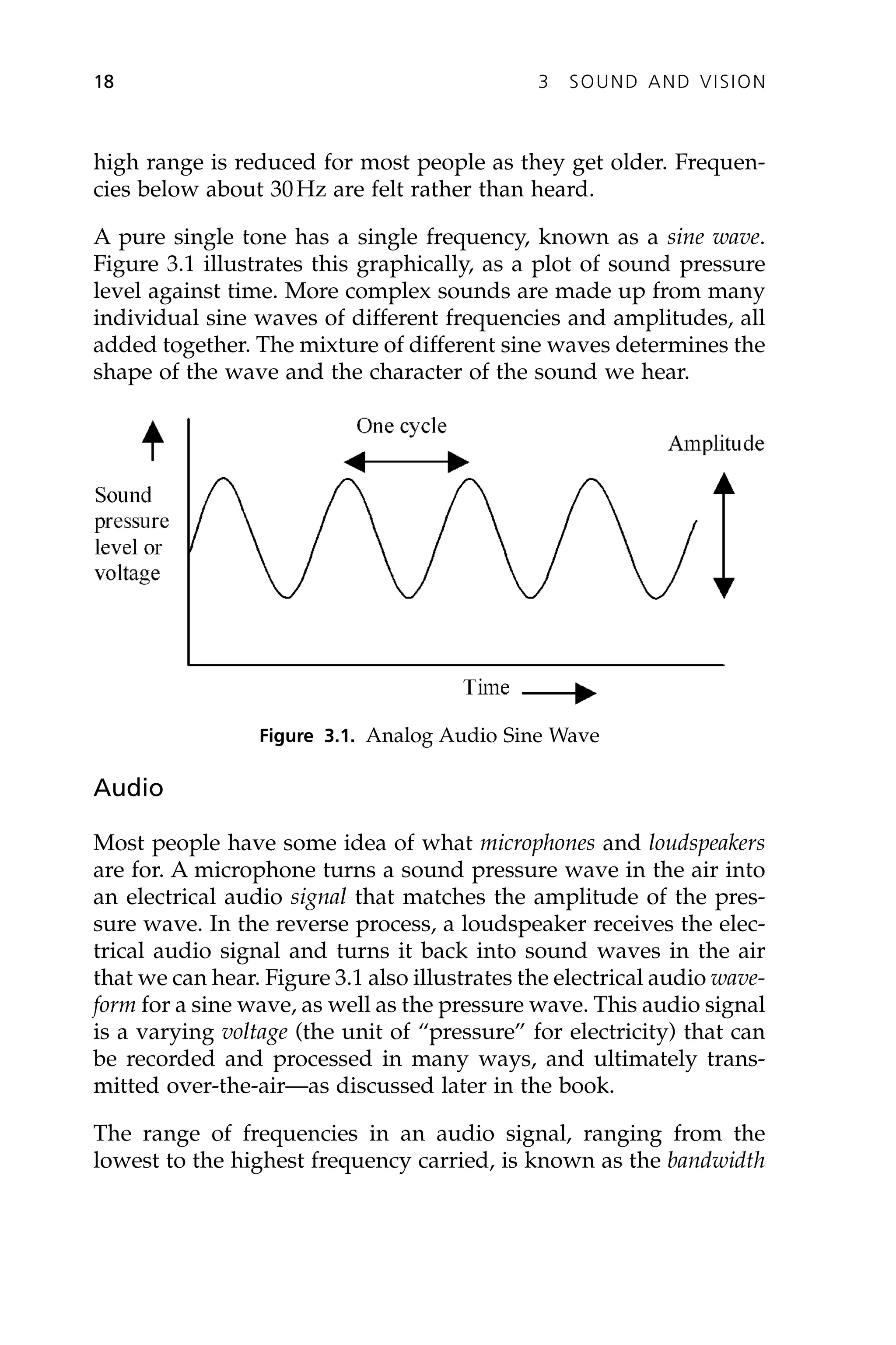
A pure single tone has a single frequency, known as a sine wave.
Figure 3.1 illustrates this graphically, as a plot of sound pressure
level against time. More complex sounds are made up from many
individual sine waves of different frequencies and amplitudes, all
added together. The mixture of different sine waves determines the
shape of the wave and the character of the sound we hear.
18 3 SOUND AND VISION
Figure 3.1. Analog Audio Sine Wave
Audio
Most people have some idea of what microphones and loudspeakers
are for. A microphone turns a sound pressure wave in the air into
an electrical audio signal that matches the amplitude of the pres-
sure wave. In the reverse process, a loudspeaker receives the elec-
trical audio signal and turns it back into sound waves in the air
that we can hear. Figure 3.1 also illustrates the electrical audio wave-
form for a sine wave, as well as the pressure wave. This audio signal
is a varying voltage (the unit of “pressure” for electricity) that can
be recorded and processed in many ways, and ultimately trans-
mitted over-the-air—as discussed later in the book.
The range of frequencies in an audio signal, ranging from the
lowest to the highest frequency carried, is known as the bandwidth
38.
of the signal.The range of frequencies that can be passed, combined
with information on how accurately their amplitudes are repro-
duced, is known as the frequency response of the equipment or
system.
With analog audio, the electrical signal is a direct equivalent of the
sound pressure wave that it represents. However, it is possible for
an analog signal to lose some of its frequencies or to have distortion
and noise added to it as it passes through the signal chain from
source to listener. Losing high or low frequencies makes the sound
lacking in treble or bass; distortion makes the sound harsh and
unpleasant, and noise of various sorts makes it more difficult to
hear the original sound clearly. Therefore, analog audio is often
converted to more robust digital signals for processing and trans-
mission, with many advantages, as described later.
Mono, Stereo, and Surround Sound
Sounds picked up with a single microphone can be carried through
a signal chain as a single channel, and end up being played to a lis-
tener on a single loudspeaker. Such a source and system is known
as monophonic or mono. The drawback of mono audio is that it does
not provide the listener with any real sense of direction or space
for the sounds. If the sounds are picked up with two or more micro-
phones, carried to the listener over two separate channels, and
played over two loudspeakers, left and right, then it is possible to
provide a good impression of the position of the sound in the orig-
inal studio. Such a system is known as stereophonic or stereo, and is
widely used in audio recording, radio, and television.
Stereo systems are, however, unable to give an impression of the
direction of sounds coming from the sides or behind the listener,
or to give a proper impression of the acoustics of the space. This
can be achieved by using multiple, properly positioned micro-
phones, a multichannel signal chain, and multiple loudspeakers
positioned in front of and around the listener. This is known as a
surround sound system.
3 SOUND AND VISION 19
39.
Light and Video
Lightand Color
We have learned that sound is a vibration, generated by the source
of sound, that produces a pressure wave, which makes the eardrum
vibrate, and so we hear the sound. In a similar manner, light is a
type of wave (an electromagnetic wave) that is generated by the
source of light, which stimulates the retina in the eye so we can see
it. Just as the amplitude of the sound wave determines the loud-
ness of the sound, the amplitude of the light wave determines the
brightness of the light, which is referred to as the luminance level.
The frequency of the sound wave determines whether we hear a
low or a high tone, and similarly for light, the frequency of the
wave determines what color we see, referred to as its hue. One other
characteristic of colored light is its saturation. Saturation refers to
how “strong” the color is, or, to put it another way, how much it
has been diluted with white light. For example, a deep bright red
is very saturated, whereas a light pink may have the same hue, but
with a low saturation.
What we see as white light is, in fact, made up of a mixture of many
colors that the brain interprets as being white. This can be demon-
strated by shining a white light through a glass prism, which splits
up the different colors so they can be seen individually. That also
happens when we see a rainbow. In that case, each raindrop acts
as a tiny prism, and the white sunlight is split up into all the colors
of the rainbow. What is perhaps more surprising is that the same
sensation of white light in the eye can be produced by mixing
together just three colors in the right proportion. For light mixing,
these primary colors are red, green, and blue, also referred to as R,
G, and B.
By mixing two of these colors together, we can produce other
secondary colors, so:
Red + Green = Yellow
Red + Blue = Magenta
Green + Blue = Cyan
20 3 SOUND AND VISION
40.
By mixing theprimary colors in different proportions, we can actu-
ally produce most other visible colors. This important property
means that the light from any color scene can be split up, using
color filters or a special sort of prism, into just the three primary
colors of red, green, and blue, for converting into television
pictures.
Characteristics of the Human Eye
We mentioned previously that the retina in the eye is stimulated
by light, and we then see the scene. The human eye and brain per-
ceive different light frequencies as different colors. Several other
characteristics of human vision are significant in this process. One
of these is that the eye sees much less color detail compared to the
detail it sees in the brightness, or luminance, of a scene. This greatly
affects the way that color signals are carried in color television
systems (see the sections on chrominance in Chapter 5 and color
subsampling in Chapter 6). Another characteristic is called persist-
ence of vision. After an image being viewed has disappeared, the eye
still sees the image for a fraction of a second (just how long depends
on the brightness of the image). This allows a series of still pictures
in both television and cinematography to create the illusion of a
continuous moving picture.
Video
Most people have some idea of what television cameras and tele-
vision receivers or picture monitors are used for. In summary, a color
camera turns the light that it receives into an electrical video signal
for each of the three primary red, green, and blue colors. In the
reverse process, a television display or picture monitor receives the
electrical video signal and turns it back into red green, and blue
light that we can see. Our eyes combine the red, green, and blue
images together so we see the full color scene. The video signal that
carries the image is a varying voltage, and that signal can be
recorded and processed in many ways and transmitted over-the
air—as covered later in this book.
3 SOUND AND VISION 21
41.
With analog video,the electrical video signal is a direct equivalent
of the luminance of the light that it represents (and in a more com-
plicated way, also of the color hue and saturation). However, it is
possible for an analog signal to have distortion and noise added to
it as it passes through the signal chain from source to viewer. Dif-
ferent types of distortion change the picture in many ways, making
it soft and fuzzy, adding a “ghost” image, or changing the colors.
Video noise may be seen as “snow” or random spots or patterns
on the screen. Therefore, analog video is often converted to more
robust digital signals for processing and transmission, with many
advantages, as described in later chapters.
Baseband
The audio and video signals we have mentioned, directly repre-
senting sound and image information, are referred to as baseband
signals. They can be carried as varying voltages over wires and
cables and can be processed by various types of equipment. They
cannot, however, be transmitted over-the-air by themselves. For
that they need to be combined in a special way, called modulation,
with radio frequency signals, as discussed in the next chapter.
22 3 SOUND AND VISION
42.
CHAPTER 4
Radio FrequencyWaves
This chapter describes some of the scientific principles of
radio waves that are fundamental to all types of broadcasting
transmission.
Electromagnetic Waves
It is fairly easy to understand that sound waves can be carried
through the air, just as waves move on the sea. Although more dif-
ficult to explain, as mentioned earlier, light can also be considered
as an electromagnetic wave. In simple terms, electromagnetic waves
are vibrations of electrical and magnetic energy that can travel long
distances, even through the vacuum of space or, to a variable
extent, through other materials. They are the foundation of
broadcasting.
Types of Waves
Electromagnetic waves have a range of frequencies, most of them
far higher than the sound waves described previously. The waves
have very different properties, depending on the frequency, and the
following types make up the electromagnetic radiation spectrum.
Starting from the lowest frequencies, they are as follows:
• Radio waves
• Microwaves (very short radio waves)
• Infrared waves
• Light waves
23
43.
• Ultraviolet waves
•X-rays
• Gamma rays
Radio waves are usually referred to as RF, standing for radio fre-
quency. In the early days of radio, the term ether was invented to
describe the undetectable medium that carries electromagnetic
waves. However, experiments have shown that the ether does not
actually exist and no medium is required to carry the waves, which
are a form of energy, but you still sometimes hear people refer to
radio “traveling through the ether.”
Frequency, Wavelength, and Amplitude
Radio waves come in a range of frequencies and wavelengths. Those
used for broadcasting in the United States range from about 500kHz
to 12GHz. As mentioned for sound, a hertz (Hz) is one cycle of the
wave per second. The units used for RF frequencies are as follows:
kHz kilo (thousand) hertz
MHz mega (million) hertz
GHz giga (billion) hertz
Whatever their frequency, all electromagnetic waves travel through
a vacuum at the speed of light (about 186,000 miles per second, or
300 million meters per second). This speed is almost the same in
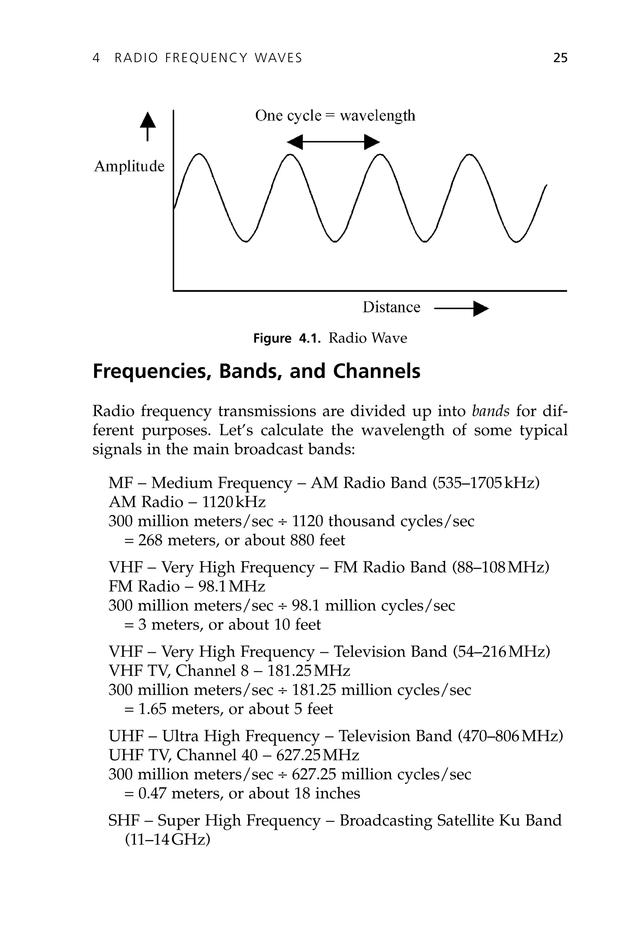
air, but it decreases in other materials. Figure 4.1 represents a radio
wave as it travels through space; the wavelength is the distance that
one “wave” or cycle of a signal occupies. Waves with short wave-
lengths have high frequencies, and those with longer wavelengths
have lower frequencies. It is easy to calculate the wavelength of a
signal if you know its frequency, because the frequency multiplied
by the wavelength always equals the speed of light. Therefore, the
wavelength in meters is approximately 300 million divided by the
frequency.
As shown in the figure, radio waves have an amplitude as well as
a frequency—just like sound waves.
24 4 RADIO FREQUENCY WAVES
44.
Frequencies, Bands, andChannels
Radio frequency transmissions are divided up into bands for dif-
ferent purposes. Let’s calculate the wavelength of some typical
signals in the main broadcast bands:
MF - Medium Frequency - AM Radio Band (535–1705kHz)
AM Radio - 1120kHz
300 million meters/sec ∏ 1120 thousand cycles/sec
= 268 meters, or about 880 feet
VHF - Very High Frequency - FM Radio Band (88–108MHz)
FM Radio - 98.1MHz
300 million meters/sec ∏ 98.1 million cycles/sec
= 3 meters, or about 10 feet
VHF - Very High Frequency - Television Band (54–216MHz)
VHF TV, Channel 8 - 181.25MHz
300 million meters/sec ∏ 181.25 million cycles/sec
= 1.65 meters, or about 5 feet
UHF - Ultra High Frequency - Television Band (470–806MHz)
UHF TV, Channel 40 - 627.25MHz
300 million meters/sec ∏ 627.25 million cycles/sec
= 0.47 meters, or about 18 inches
SHF - Super High Frequency - Broadcasting Satellite Ku Band
(11–14GHz)
4 RADIO FREQUENCY WAVES 25
Figure 4.1. Radio Wave
45.
Direct Broadcast Satellite,Transponder 30 - 12.647GHz
300 million meters/sec ∏ 12.647 billion cycles/sec
= 2.37 centimeters, or about 1 inch
As this exercise illustrates, the wavelength of an AM radio signal
is much longer than the wavelength of an FM radio signal, which
is significantly longer than the wavelength of a UHF TV signal.
Because of these differing wavelengths, there are big differences
between the antenna types used to transmit and receive AM, FM,
and TV signals. The wavelengths used for direct broadcast satel-
lites are even shorter, which explains why the antennas used (small
dishes) are so different from other types of broadcast antennas.
Each radio band is further divided into channels, each with a range
of frequencies. The range of frequencies from lowest to highest is
known as the channel bandwidth. The term may also refer to any
particular range of frequencies, not only in RF.
The UHF and SHF bands have further subdivisions, with bands
that are used for terrestrial radio links, satellite links, and for satel-
lite broadcasting. These include the L, S, C, X, Ku, K, and Ka bands,
with frequencies from about 1GHz to 40GHz.
Properties
Because of the varying wavelengths, waves in different bands have
different propagation properties. In particular, the shorter the
wavelength, the more the wave tends to travel in straight lines and
to be blocked by obstacles in its path. Longer waves, such as in the
AM medium frequency band, tend to “flow” around obstructions
and propagate in different ways, with a ground wave and a sky wave.
See Chapter 17 for details.
RF Over Wires and Cables
As described previously, RF waves travel through space as elec-
tromagnetic waves. However, it is important to understand that the
26 4 RADIO FREQUENCY WAVES
46.
same RF frequenciescan be carried as varying electrical voltages
over copper wires and cables, just like baseband audio and video
signals. However, the distance they can travel over wires is
restricted by the signal loss in the cable at RF frequencies.
Modulation
Carriers and Subcarriers
Sound and light waves are baseband signals that carry information
that people can hear and see directly, but radio waves are used to carry
sound, pictures, and other information over long distances. Therefore,
radio waves are often referred to as the carrier or carrier wave. They
carry information by varying one or more of their characteristics: this
is called modulation. In traditional analog broadcasting, the character-
istics that are varied are the amplitude and frequency, but there are
several other, more complex, modulation methods used for different
purposes, as discussed in the following sections.
The term subcarrier has two meanings. It may refer to a modulated
carrier that is combined with other signals and then modulated
onto a higher carrier frequency. It also sometimes refers to the use
of multiple carriers of similar frequencies in one system (e.g.,
COFDM, as mentioned later in this chapter).
Modulation for the broadcast signal takes place as part of the trans-
mission process (see Chapter 16).Aradio or television receiver picks
up the transmitted radio waves and selects the correct RF channel
with a tuner. It then performs demodulation in order to recover the
program information that was carried by the radio wave, convert-
ing it back to baseband audio, video, and perhaps data, signals.
Amplitude Modulation
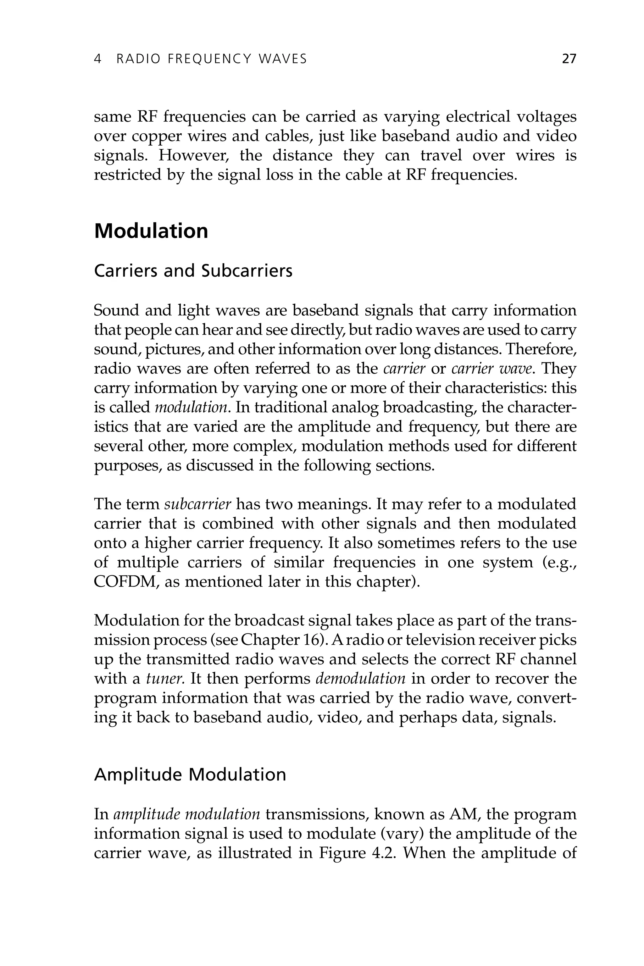
In amplitude modulation transmissions, known as AM, the program
information signal is used to modulate (vary) the amplitude of the
carrier wave, as illustrated in Figure 4.2. When the amplitude of
4 RADIO FREQUENCY WAVES 27
47.
the program signalis zero, the carrier remains unmodulated. As
the instantaneous amplitude of the signal increases up to its
maximum, then the carrier amplitude varies accordingly, up to the
maximum amount—100 percent modulation.
28 4 RADIO FREQUENCY WAVES
Program signal Modulated carrier wave
Carrier
Figure 4.2. Amplitude Modulation
Program signal Modulated carrier wave
Carrier
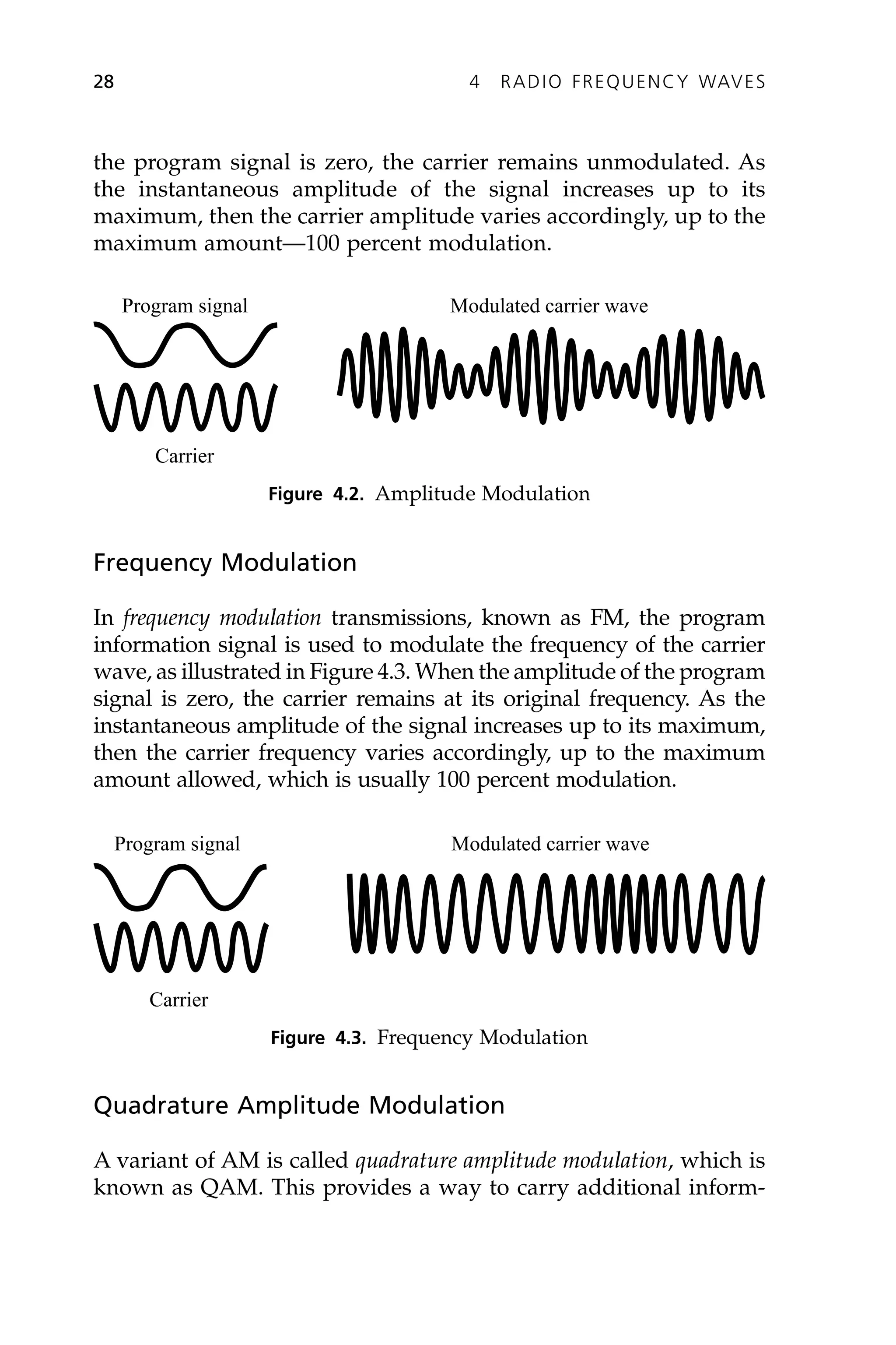
Figure 4.3. Frequency Modulation
Frequency Modulation
In frequency modulation transmissions, known as FM, the program
information signal is used to modulate the frequency of the carrier
wave, as illustrated in Figure 4.3. When the amplitude of the program
signal is zero, the carrier remains at its original frequency. As the
instantaneous amplitude of the signal increases up to its maximum,
then the carrier frequency varies accordingly, up to the maximum
amount allowed, which is usually 100 percent modulation.
Quadrature Amplitude Modulation
A variant of AM is called quadrature amplitude modulation, which is
known as QAM. This provides a way to carry additional inform-
48.
ation in sometypes of radio and television transmission without
using significant extra bandwidth. In particular, it is used to carry
supplementary services in AM radio and, with a subcarrier, to carry
the chrominance information in NTSC television.
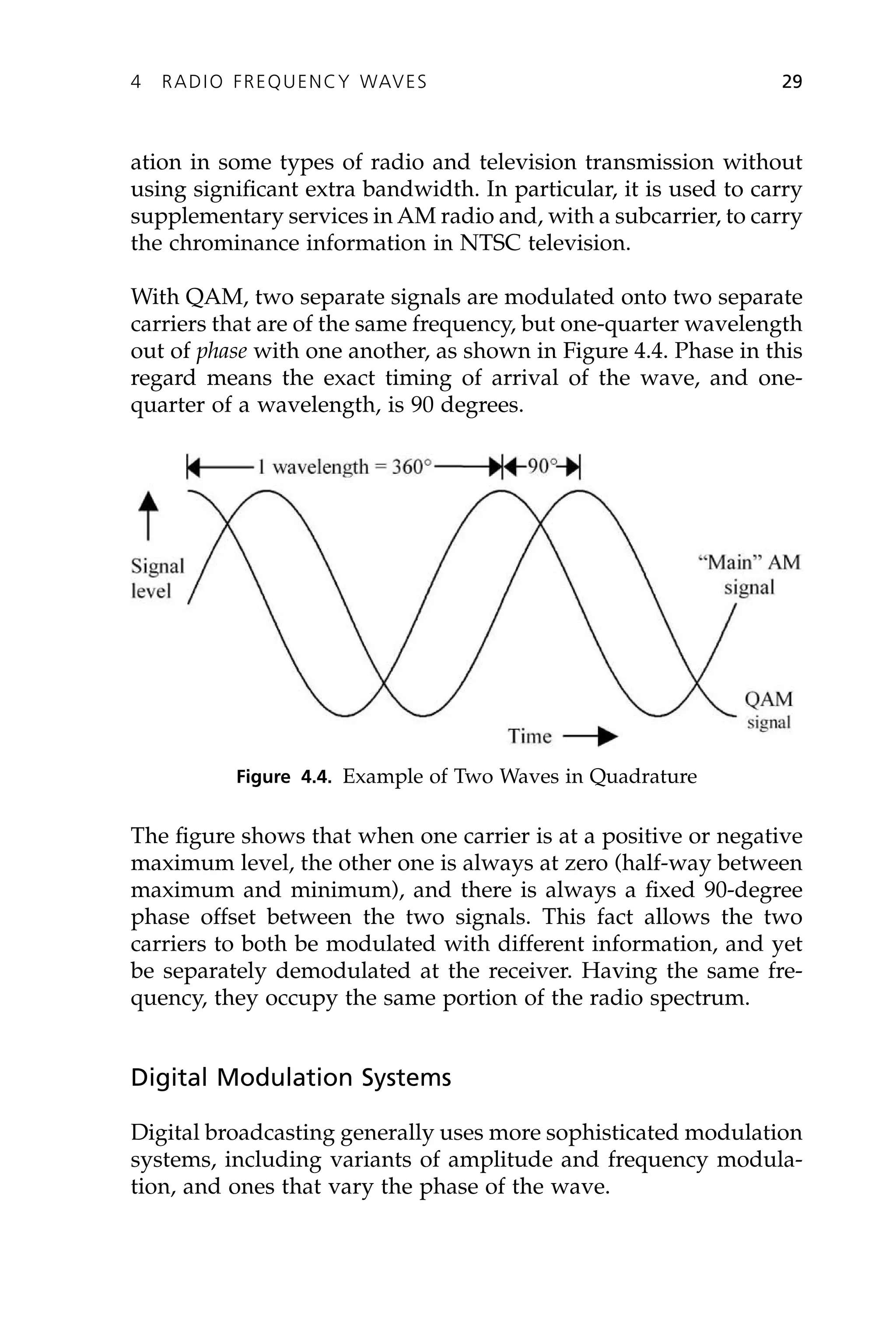
With QAM, two separate signals are modulated onto two separate
carriers that are of the same frequency, but one-quarter wavelength
out of phase with one another, as shown in Figure 4.4. Phase in this
regard means the exact timing of arrival of the wave, and one-
quarter of a wavelength, is 90 degrees.
4 RADIO FREQUENCY WAVES 29
Figure 4.4. Example of Two Waves in Quadrature
The figure shows that when one carrier is at a positive or negative
maximum level, the other one is always at zero (half-way between
maximum and minimum), and there is always a fixed 90-degree
phase offset between the two signals. This fact allows the two
carriers to both be modulated with different information, and yet
be separately demodulated at the receiver. Having the same fre-
quency, they occupy the same portion of the radio spectrum.
Digital Modulation Systems
Digital broadcasting generally uses more sophisticated modulation
systems, including variants of amplitude and frequency modula-
tion, and ones that vary the phase of the wave.
49.
In ATSC digitaltelevision, 8-VSB is used—an eight-level amplitude
modulation system. This method is discussed further in Chapter
15. Several versions of QAM are used for digital transmission
systems (e.g., in AM IBOC radio and digital cable television). In
this case, the two carriers are modulated to various discrete levels
that, taken together, represent a particular digital symbol. There
may be different numbers of symbols (typically 16, 64, or 256),
depending on the application.
Modulation systems where the phase of the wave is varied, for
example the various versions of phase shift keying (PSK), are also
used, particularly for digital satellite broadcasting. The theory gets
very technical, so we won’t cover it here.
Pulse code modulation (PCM) refers to a particular method of carry-
ing signals in digital form. It actually occurs at baseband (e.g., as
used for compact discs) although PCM signals may also be modu-
lated onto an RF carrier.
COFDM
Various systems for digital transmission use modulation of multi-
ple carriers to make the signal more robust, particularly so it can
resist multipath reception conditions. COFDM, the coded orthogonal
frequency division multiplex system is used for IBOC, DAB, DRM,
DVB-T, and ISDB-T broadcasting (as well as for the repeaters used
with satellite radio systems), and for electronic newsgathering
(ENG) digital radio links.
The COFDM signal is composed of thousands of separate subcar-
rier frequencies, each of which carries a relatively low-speed digital
data stream. Techniques such as interleaving and forward error cor-
rection (FEC) enable a receiver that fails to pick up some of these
subcarriers, nevertheless to recover the main signal. This makes the
signal very robust and easier to receive under difficult conditions.
Again, the theory gets rather technical, so we won’t go into further
details.
30 4 RADIO FREQUENCY WAVES
50.
Sidebands
When an RFcarrier (or subcarrier) wave of a particular frequency
is modulated with a signal of another frequency, the resulting RF
signal has additional RF components called sidebands. Sideband fre-
quencies are typically the carrier frequency, plus or minus a whole
multiple (1¥, 2¥, etc.) of the modulating frequency. It is these side-
bands produced by modulation that carry the actual information
in the radio wave.
As an example for AM, a carrier wave of, say, 650kHz, amplitude
modulated with an audio signal of 10kHz, will produce a com-
posite signal comprising the original carrier of 650kHz plus an
upper sideband of 660kHz and a lower sideband of 640kHz. The
number and size of the sidebands depends on the type of modu-
lation, but they always extend both above and below the original
carrier frequency. In some cases, it is possible to transmit only part
of the sidebands and still recover the program information at the
receiver. In other cases, the main carrier is suppressed and only the
sidebands are transmitted.
This concept of sidebands is important because it affects the
amount of radio spectrum, or bandwidth, used for a given type of
transmission—this is discussed later in the chapters on broadcast
standards.
Light Modulation
For completeness, it should be mentioned that light waves can also
be modulated in intensity to carry information. The two most
common applications are for film optical sound tracks and for car-
rying audio, video, and data over fiber-optic links.
4 RADIO FREQUENCY WAVES 31
Welcome to ourwebsite – the ideal destination for book lovers and
knowledge seekers. With a mission to inspire endlessly, we offer a
vast collection of books, ranging from classic literary works to
specialized publications, self-development books, and children's
literature. Each book is a new journey of discovery, expanding
knowledge and enriching the soul of the reade
Our website is not just a platform for buying books, but a bridge
connecting readers to the timeless values of culture and wisdom. With
an elegant, user-friendly interface and an intelligent search system,
we are committed to providing a quick and convenient shopping
experience. Additionally, our special promotions and home delivery
services ensure that you save time and fully enjoy the joy of reading.
Let us accompany you on the journey of exploring knowledge and
personal growth!
ebookultra.com


![Presentation1[1]abiout nhnfdfkmdjbf.pptx](https://cdn.slidesharecdn.com/ss_thumbnails/presentation11-240718051625-2893c777-thumbnail.jpg?width=640&height=640&fit=bounds)


