Hfc b headend of hfc
•
1 like•2,510 views

Here are the key points about television standards around the world: - The main standards are NTSC, PAL, and SECAM. - NTSC is used in North America, parts of South America, and Japan. It has 525 lines, 59.94 fields/second. - PAL is used in Europe, parts of Asia, Africa, and some of South America. It has 625 lines, 50 fields/second. - SECAM was developed in France and used in former Soviet countries. It also has 625 lines, 50 fields/second. - Variations include PAL-M in Brazil (525 lines, 30 frames/second) and PAL-N in parts of

Recommended
More Related Content
What's hot
What's hot (20)
Viewers also liked
Viewers also liked (20)
Similar to Hfc b headend of hfc
Similar to Hfc b headend of hfc (20)
More from jose angel guzman lozano
Recently uploaded
Recently uploaded (20)
Hfc b headend of hfc
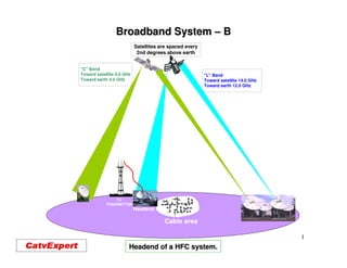
- 1. Broadband System – B Satellites are spaced every 2nd degrees above earth "C" Band Toward satellite 6.0 GHz "L" Band Toward earth 4.0 GHz Toward satellite 14.0 GHz Toward earth 12.0 GHz TV TRANSMITTER Headend Cable area 1 Headend of a HFC system.
- 2. Welcome to a Seminar on Broadband Network. Please, fell free to stop me at any time during this seminar and ask me any questions you want. If you are viewing this seminar by INTERNET, you can send me an e-mail with a proper question and I will do my best to answer your question. My e-mail is : lamarrea@videotron.ca 2
- 3. Welcome to a Seminar on Broadband Network. Here are the subjects that we will be covering during the future seminars; •The Coaxial cable. •The RF section of the Broadband system. •The Distortions on a Broadband system. •The Passives equipments. •The Maintenance of the CATV, HFC system. •The Test equipments for a Broadband system. •Understanding Bi-directionality of a Broadband system. •Understanding Cablemodem, QPSK, 64 and 256 QAM signal. 3
- 4. Decisions to Render Before Building a Broadband Network. •Getting the proper licences from the various governing body. •Selection of the proper Receiving and Transmitting site (s). •Selection of the maximum bandwidth (MHz) of the system. •Selection of the type of transmission technology. (Analog, Digital, etc.) •Selection of the number of Analog and Digital channels to be carried. •Utilisation of the return spectrum. •Selecting the NODE location. •Selecting the number of subscribers per NODE. •Choice of the distribution route. •Selection of the maximum length of the coaxial section. •Choice of the amplifier technology. (Power Doubling, GaAs) 4
- 5. Decisions to Render Before Building a Broadband Network. (Suite) •Selection of the size and the type of the coaxial cable. •Determining the RF signal level required at each customer. •Selecting the right coaxial connectors. •Selecting of the passive equipments. •Selecting the contractor (s) . •Hiring and training the technicians. •Selecting the equipments for the Maintenance and the proper Operation of the system. •Determining a routine maintenance. 5
- 6. Definition of dB, dBmV. dB (Decibel) The decibel is a logarithmic ratio between two power level: P1 dBPOWER =10log10 P2 Rule: 3dB is twice the power, and 10 dB is 10 times the power. A voltage ratio for equal impedance is expressed as: E1 dBvoltage =20log10 E2 Rule: 6 dB is twice the voltage, and 20 dB is 10 times the voltage. 6
- 7. Definition dBmV and dB Micro Volts. •In European dB Micro Volt, is used to read power level on CATV system. •In North America, dBmV is used to read power level of television signal. The difference between dBmV and dBuV is 60. dBmV dBuV -40 20 -30 30 -10 50 0 60 Customer TV Level 10 70 30 90 32 98 40 100 Amp. Output 44 104 H.E. Equip.Level 60 120 80 140 7
- 8. The Headend of a Broadband System 8
- 9. Headend of a Broadband System. •The purpose of this seminar is to familiarize students with a better understanding of all the equipments necessary for the Headend (Control System ) of a Broadband System. •This seminar will not only show the television control equipments needed for operating the CATV system, it will also show the fiber optic interconnection system. •It is also a good way to get the system technician to better understand what is going on at the headend. 9
- 10. Television Standards in the World. A short vision on the different types of television standards used in the world. NTSC = National Television Standard Committee. In service in the USA, Canada, Japan and Mexico. SECAM = Sequentiel Couleur Avec Memoires In service in USSR, Bulgaria, East Germany, and certain region of France. PAL = Phase Alternative Line. In service in Central Europe, France, Italy and Switzerland. Many types of PAL system exits; Pal-B, Pal-D, Pal-G. 10
- 11. Television Standard for North America. •NTSC stands for National Television System Committee, which devised the NTSC television broadcast system in 1951. NTSC is also commonly used to refer to one type of television signal that can be recorded on various tape formats such as VHS, 3/4" U-matic and Beta cam. •The NTSC standard has a fixed vertical resolution of 525 horizontal lines stacked on top of each other, with varying amounts of "lines" making up the horizontal resolution, depending on the electronics and formats involved. There are 59.94 fields displayed per second. A field is a set of even lines, or odd lines. The odd and even fields are displayed sequentially, thus interlacing the full frame. One full frame, therefore, is made of two interlaced fields, and is displayed about every 1/30 of a second. •NTSC countries are: USA, Antigua, Bahamas, Barbados, Belize, Bermuda, Bolivia, Burma, Canada, Chile, Colombia, Costa Rica, Cuba, Dominican Republic, Ecuador, El Salvador, Greenland, Guam, Guatemala, Guyana, Honduras, Jamaica, Japan, South Korea, Mexico, Netherlands Antilles, Nicaragua, Panama, Peru, Philippines, Puerto Rico, St. Vincent & the Grenadines, St. Kitts, Samoa, Surinam, Taiwan, Tobago, Trinidad, Venezuela, Virgin Islands. 11
- 12. Television Standard for North America. NTSC; National Television System Committee. Developed in the US, it was the world’s first colour TV system. Broadcast started in 1954. 12
- 13. Spectrum Analyzer View of a NTSC Signal. Line field: 525/60 Horizontal freq.: 15.734 kHz Vertical freq.: 60 Hz Colour sub. Freq.: 3.579545 MHz Video bandwidth : 4.2 MHz Audio carrier : 4.5 MHz (FM) Video Information Audio information. Colour Information. Channel frequency Ex: ch –2 = 55.25 MHz ch -13= 211.25 MHz 13
- 14. Television Standard for Other Country. PAL stands for Phase Alternation by Line, and was adopted in 1967. It has 625 horizontal lines making up the vertical resolution. 50 fields are displayed and interlaced per second, making for a 25 frame per second system. An advantage of this system is a more stable and consistent hue (tint). PAL-M is used only in Brazil. It has 525 lines, at 30 frames per second. PAL countries include: Afghanistan, Algeria, Argentina (PAL-N), Australia, Austria, Bahrain, Bangladesh, Belgium, Brunei, Cameroon, Canary Islands, China, Cyprus, Denmark, Finland, Germany, Ghana, Gibraltar, Greece (also SECAM), Hong Kong, Iceland, India, Indonesia, Ireland, Israel, Italy, Jordan, Kenya, North Korea, Kuwait, Liberia, Luxembourg (also SECAM), Madeira, New Zealand, Nigeria, Norway, Oman, Pakistan, Paraguay (PAL-N), Portugal, Qatar, Saudi Arabia (also SECAM), Sierra Leone, Singapore, South Africa, Spain, Sri Lanka, Sudan, Swaziland, Tanzania, Thailand, Turkey, Uganda, United Arab Emirates, United Kingdom, Uruguay (PAL-N), Yemen (the former Yemen Arab Republic was PAL, and the former People's Democratic Republic of Yemen was NTSC ), Yugoslavia, Zambia, Zimbabwe. 14
- 15. Television Standard for Other Country. PAL : Phase Alternation Line. Developed in Germany. Broadcast started in 1967. 15
- 16. Spectrum Analyzer View of a PAL-B-G-H Signal. Line field: 625/50 Horizontal freq.: 15.325 kHz Vertical freq.: 50 Hz Colour sub. Freq.: 4.436618 MHz Video bandwidth : 5.0 MHz Audio carrier : 5.5 MHz (FM) 16
- 17. Television Standard for Other Country. SECAM stands for Systeme Electronique Couleur Avec Memoire, which was adopted in 1967. It has 625 lines and 25 frames per second. SECAM Countries include: Albania, Benin, Bulgaria, Congo, former Czechoslovakia, Djibouti, Egypt, France, French Guiana, Gabon, Greece (also PAL), Guadeloupe, Haiti, Hungary, Iran, Iraq, Ivory Coast, Lebanon, Libya, Luxembourg (also PAL), Madagascar, Martinique, Mauritius, Monaco (also PAL), Mongolia, Morocco, New Caledonia, Niger, Poland, Reunion, Romania, Saudi Arabia (also PAL), Senegal, Syria, Tahiti, Togo, Tunisia, former USSR, Viet Nam, Zaire. SECAM audio system use AM modulation. It is then near impossible to reduce the audio level by 14 to 16 dB, like PAL and NTSC system. It is then impossible to put adjacent channel on a Broadband system. 17
- 18. Television Standard for Other Country. SECAM : Sequential Couleur Avec Memoire. Developed in France. Broadcast started in 1967 18
- 19. Spectrum Analyzer View of a SECAM-D-K-K1-L Signal. Line field: 625/50 Horizontal freq.: 15.625 kHz Vertical freq.: 50 Hz Colour sub. Freq.: 4.436618 MHz Video bandwidth : 5.0 MHz Audio carrier : 5.5 MHz (AM) 19
- 20. Ways of Receiving Television Signal at a Headend. •By RF antenna, from a ( VHF or UHF ) transmitter. •By satellite transmission (4 or 12 GHz). •By Fiber optic transport system. •By Microwave. •By specialized digital distribution system. (QAM, ASI, FM, HDTV) •By local origination (local program). 20
- 21. Over the Air Television Signal. Low band VHF: Ch. Video Audio 2- 55.25 59.75 3- 61.25 65.75 4- 67.25 71.75 73.5 0 Emergency frequency. 5- 77.25 81.75 6- 83.25 87.75 These TV signals are transmitted over the air by a television transmitter. 21
- 22. Over the Air Television Signal. High band VHF: Ch. Video Audio 7 175.25 179.75 8 181.25 185.75 9 187.25 191.25 10 193.25 197.75 11 199.25 203.75 12 205.25 209.75 13 211.25 215.75 These TV signals are transmitted over the air by a television transmitter. 22
- 23. Spectrum of Television Signal Over the Air. FM stations 73.5 2 6 7 13 55.25 88 108 211.25 175.25 MHz MHz MHz MHz MHz You are seeing here the complete VHF signals over the air. 23
- 24. Video Frequency of TV Channel on a Broadband System. Ch. (MHz) Ch. (MHz) Ch. (MHz) Ch. (MHz) Ch. (MHz) Ch. (MHz) 2 55.25 7 175.25 31 265.25 46 355.25 61 451.25 76 535.25 3 61.25 8 181.25 32 271.25 47 361.25 62 457.25 77 541.25 4 67.25 9 187.25 33 277.25 48 367.25 63 463.25 78 547.25 • 73.50 10 193.25 34 283.25 49 373.25 64 469.25 79 553.25 5 77.25 11 199.25 35 289.25 50 379.25 65 475.25 80 559.25 6 83.25 12 205.25 36 295.26 51 385.25 66 481.25 81 565.25 14 121.25 13 211.25 37 301.25 52 391.25 67 487.25 82 571.25 15 127.25 23 217.25 38 307.253 53 397.25 68 493.25 83 577.25 16 133.25 24 223.25 39 313.25 54 403.25 69 499.25 84 583.25 17 139.25 25 229.25 40 319.25 55 409.25 70 505.25 85 589.25 18 145.25 26 235.25 41 ***** 56 415.25 71 511.25 86 595.25 19 151.25 27 241.25 42 ***** 57 421.25 72 517.25 87 601.25 20 157.25 28 247.25 43 337.25 58 427.25 73 523.25 88 607.25 21 163.25 29 253.25 44 343.25 59 433.25 74 529.25 89 613.25 22 169.25 30 259.25 45 349.25 60 439.25 75 535.25 90 619.25 24
- 25. Video Frequency of TV Channel on a Broadband System. Ch. (MHz) Ch. (MHz) Ch. (MHz) Ch. (MHz) 91 625.25 106 685.25 121 775.25 136 865.25 92 631.25 107 691.25 122 781.25 137 871.25 93 637.25 108 697.25 123 787.25 138 877.25 94 643.25 109 703.25 124 793.25 139 883.25 95 91.25 110 709.25 125 799.25 140 889.25 96 97.25 111 715.25 126 805.25 141 865.25 97 103.25 112 721.25 127 811.25 142 901.25 98 109.25 113 727.25 128 817.25 143 907.25 99 115.25 114 733.25 129 823.25 144 913.25 100 649.25 115 739.25 130 829.25 145 919.25 101 655.25 116 745.25 131 835.25 146 925.25 102 661.25 117 751.25 132 841.25 147 931.25 103 667.25 118 757.25 133 847.25 148 937.25 104 673.25 119 763.25 134 853.25 149 943.25 105 679.25 120 769.25 135 859.25 150 949.25 25
- 26. Video Frequency of FM Channel on a Broadband System. 1 88.1 21 92.1 41 96.1 61 100.1 81 104.1 2 88.3 22 92.3 42 96.3 62 100.3 82 104.3 3 88.5 23 92.5 43 96.5 63 100.5 83 104.5 4 88.7 24 92.7 44 96.7 64 100.7 84 104.7 5 88.9 25 92.9 45 96.9 65 100.9 85 104.9 6 89.1 26 93.1 46 97.1 66 101.1 86 105.1 7 89.3 27 93.3 47 97.3 67 101.3 87 105.3 8 89.5 28 93.5 48 97.5 68 101.5 88 105.5 9 89.7 29 93.7 49 97.7 69 101.7 89 105.7 10 89.9 30 93.9 50 97.9 70 101.9 90 105.9 11 90.1 31 94.1 51 98.1 71 102.1 91 106.1 12 90.3 32 94.3 52 98.3 72 102.3 92 106.3 13 90.5 33 94.5 53 98.5 73 102.5 93 106.5 14 90.7 34 94.7 54 98.7 74 102.7 94 106.7 15 90.9 35 94.9 55 98.9 75 102.9 95 106.9 16 91.1 36 95.1 56 99.1 76 103.1 96 107.1 17 91.3 37 95.3 57 99.3 77 103.3 97 107.3 18 91.5 38 95.5 58 99.5 78 103.5 98 107.5 19 91.7 39 95.7 59 99.7 79 103.7 99 107.7 20 91.9 40 95.9 60 99.9 80 103.9 100 107.9 26
- 27. Headend Equipment for a Broadband System. Signal Processor. 6.0 MHz 6.0 MHz 0 0 -10 -10 -20 -20 -30 -30 dB -40 dB -40 -50 -50 -60 -60 -70 -70 3.59 MHz 3.59 MHz 4.5 MHz 4.5 MHz 13 IF 2 RF Signal IF RF Signal Input Signal Output 27
- 28. Headend Equipment for a Broadband System. Demodulator 6.0 MHz 0 -10 -20 -30 dB -40 -50 -60 -70 3.59 MHz 4.5 MHz 13 Baseband 28
- 29. Headend Equipment for a Broadband System. Modulator 6.0 MHz 0 -10 -20 -30 dB -40 -50 -60 -70 3.59 MHz 4.5 MHz Baseband 13 29
- 30. Headend Equipment for a Broadband System. Digital Signal. Satellite receiver. 6.0 MHz 0 -10 -20 Analog -30 Signal. dB -40 -50 -60 -70 3.59 MHz 4.5 MHz 30
- 31. Headend Equipment for a Broadband System. SONET, Multiservices Broadband Transport Solution CMTS server 31
- 32. Headend Equipment for a Broadband System. QPSK or 16 QAM Return Path Demodulator 32
- 33. Headend Equipment for a Broadband System. High Definition Decoder HDTV 33
- 34. Headend Equipment for a Broadband System. FM Broadcast Channel Processor FM Channel Modulator 34
- 35. Headend Equipment for a Broadband System. 44 channels Combining network. Headend equipment connection. Front end test point. 35
- 36. Headend Equipment for a Broadband System. 32 channels Combining network. Other can be added here. 36
- 37. Headend Equipment for a Broadband System. Combining all the headend equipments can be a major undertaking, I am showing below a 126 channels (RF, QAM, DOCSIS) to 256 output to feed the froward section of the system. 30 dB gain 870 MHz 30 dB gain 870 MHz 30 dB gain 870 MHz 30 dB gain 870 MHz 16 ways combiner 16 ways combiner 16 ways combiner 16 ways combiner 16 ways combiner 17 dB Headend Equipment 50 dBmV input 2 way splitter 16 ways combiner 17 dB Headend Equipment 50 dBmV input 30 dB gain 870 MHz 30 dB gain 870 MHz 30 dB gain 870 MHz 30 dB gain 870 MHz 16 ways combiner 16 ways combiner 16 ways combiner 16 ways combiner 16 ways combiner 17 dB +11 dBmV +15 dBmV Headend Equipment 50 dBmV input 2 way splitter 16 ways combiner 17 dB 13 dB gain 870 MHz 16 ways combiner 16 ways combiner Headend Equipment 50 dBmV input +24 dBmV +24 dBmV +24 dBmV +24 dBmV 16 ways combiner 17 dB Headend Equipment 50 dBmV input 30 dB gain 870 MHz 30 dB gain 870 MHz 30 dB gain 870 MHz 30 dB gain 870 MHz 16 ways combiner 16 ways combiner 16 ways combiner 16 ways combiner 17 dB 17 dB 2 way splitter 16 ways combiner 17 dB Headend Equipment 50 dBmV input 16 ways combiner 17 dB Headend Equipment 50 dBmV input 30 dB gain 870 MHz 30 dB gain 870 MHz 30 dB gain 870 MHz 30 dB gain 870 MHz 16 ways combiner 16 ways combiner 16 ways combiner 16 ways combiner 2 way splitter 16 ways combiner 17 dB Headend Equipment 50 dBmV input 37
- 38. Combining a Headend for a Broadband System. Combining Network from 50 to 870 - 1,000 MHz. Sometime an RF amplifier Can be required. 38
- 39. Combining a Headend for a Broadband System. Combining Network from 5 to 40 MHz. Sometime an RF Return amplifier can be required. 39
- 40. Headend for a Broadband System. 40
- 41. Possible Problems at a Headend. •Audio level. In a NTSC signal, the audio level must be adjusted to 14 to 16 dB lower than the Video level. •Co-channel problem. When two of the same TV signals comes from difference sources, one close to the receiving site and one far away. This problem usually happen in the summer day. •interference. Where another signal interfered with the desired Television signal. •Electrical interference. Spark usually coming from high power line. •Echo. Usually called “GHOST” some of the Television signal been reflected from a building, a mountain, or a roof of a barn, etc. •Bad Signal to Noise ratio. When a system try to pick up Television signal far away from its headend. 41
- 42. Audio level at a Headend. Each television channel must have their audio level adjusted between 14 to 16 dB lower than the video information. 6.0 MHz 6.0 MHz 6.0 MHz 0 -10 14/ 16 dB -20 -30 dB -40 -50 -60 -70 3.59 MHz 3.59 MHz 3.59 MHz 4.5 MHz 4.5 MHz 4.5 MHz If not, this will cause additional information on the upper and lower television channel. 42
- 43. Mixing SECAM, NTSC and PAL Signal. Below is an example why free space is required with SECAM signals. 6 MHz 6 MHz 7 MHz 6 MHz 7 MHz 5 1/2 MHz left 5 1/2 MHz left NTSC Empty SECAM Empty PAL-* PAL- Signal Space Signal Space Signal 43
- 44. Co-Channel Problem at a Headend. This problem occur when two TV station, on the same channel are been transmitted from a different part of North America. All television channels in North America Hemisphere (Canada, United States, Mexico) are assigned a +10, +20 or –10, -20 KHz from the standard frequency XXX.25 MHz. This problem happen mostly in the summer time, where radio waves seems to be transported further in the summer than in the winter. Cloud Main Transmitter Co-channel Transmitter WORLD 44
- 45. Co-Channel Problem at a Headend. Other TV signal at + .10+20-10-20 Khz 18 dB 60 dB TV channel with a 18 dB co- TV channel without co- channel Interference channel Interference 45
- 46. Signal Interference. The problem of signal interference happen in the mid band portion of the Broadband system, between 108.0 to 175.0 MHz. These signal interferences are coming from; •Air Traffic Control, •Commercial Aircraft System, •Air Signal Distress (121.50 MHz), •Civil Air Patrol, Police System, •Taxi System, •Emergency Ship Survival (156.80 MHz) and from many other communications system. These frequencies have priority over the broadband system. The interference problem can occur either at the headend and at all the customers in the system. The best way you can combat this problem, is to make sure, your system is “tight” of leakage signal. A good CLI program is the best prevention against this problem. 46
- 47. Signal Interference. Operating the spectrum analyser in the analog mode, a heavy beat was identified in the Channel 39 47
- 48. Electrical Interference. Electrical Interferences are one of the biggest problem broadband system have to combat. This problem is usually coming from high power transport system, where insulator are defective (cracked or dirty) and are arcing, causing the Television signal to be full of ‘SPARK” where sometime it is very hard to see a perfect picture. The best way to fight this problem is to keep good relationship with the power company and get them to eliminate the problem before it gets to serious. This problem is only affecting the headend signal and is rarely introduced in the Broadband system. Spark coming from bad insulators. 48
- 49. Echo Interference. Signal Signal Echo Echo Echo in a television signal is mainly a headend problem. This problem comes from an echo between a television transmitter and a receiving antenna. It can be a single or multiple echoes. This or these echoes can come from a reflection from a mountain, the roof of a barn or from a tall building situated between the transmission and receiving site. One of the way to eliminate this problem is to work with the phasing and installation of two or more antenna at the receiving site. Above picture shows where with proper stacking we can eliminated some if not all the echo signal. 49
- 50. Bad Signal to Noise Ratio. A bad Signal to Noise ratio is when a system try to receive signal which are very far away from the receiving site. A pre-amplifier can be installed in some case, but it will not fixed all the problem of a bad Ratio of Signal To Noise. We are talking here of Signal To Noise, which is the noise contained in the Video portion of the television signal. Carrier to Noise is the noise of the broadband system versus the Video Carrier of any television signal. 50
- 51. Possible Problems at a Headend. 51
- 52. Channels Plan of a 870 MHz Broadband System. FM Analog Digital 55 108 121 175 450 550 750 870 Channel plan of a fully loaded HFC system 52
- 53. Headend of a Broadband System. This seminar will show all the equipments located at the headend. 15 km 2.0 km Fiber section Coaxial section Headend 35 mt 53
- 54. Receiving VHF and UHF Signal. RF Antenna Receives Signal from: VHF Signal: 55.25 to 211.25 MHz UHF Signal: 471.25 to 801.25 MHz Pre-Amplifier Amplifies signal VHF or UHF Combiner/ Headend For all band or single channel. Splitter Bandpass Down Lead Coaxial Cable Filter RG-59, RG-6, RG-11 RG- RG- RG- RF Processor RF Processor / Demod. / Modulator De Demodulator Modulator Combining Network SNC-1000 54
- 55. Receiving Signal from Satellite. Satellite signals are digitized and have to be decoded to Video signal. Their operating frequencies are 4 GHz or 12 GHz Headend Combiner Modulator SNC-1000 Modulator Digitizer DSR-4500X 55
- 56. Headend Combining Network. 8 inputs from: Processor or Modulator This is how we combine television channels at a headend. Each channel can be a Television signal, FM signals, a QAM signal or a Cable modem signal. 8 inputs from: Processor or Modulator From other Combiner Combined Channels Output to Cable System. Low cost Combiner 56
- 57. Other Type of Equipments Required at a Headend. BP-8750 BP- CD-9200 CD- Band pass filter Channel Deletion Filter This is used at the input of a This is used where one wants Demodulator or a Processor where to replace an existing TV an adjacent TV channel is present channel by another one. BP-872250 BP- DXP-9545 Band pass filter Split Band Filter This is used at the output of a Mostly used at the input of an Demodulator or a Processor, where optical receiver, where a band these are not very high quality split is required for better C/N 57
- 58. Using a Bandpass Filter at a Headend. 58
- 59. Using a Channel Deleting Filter. 59
- 60. Other Type of Equipments Required at a Headend. DXP 9655-D / HN 9655- Headend Post Amplifier [PA-860] Amplifies TV signal before or after combining. Separates forward and return signal. Variable Notch Filter QRBA-2000 QRBA- Return amplifiers Amplifies return signals coming from a return optical link Mostly used to lower a high FM station on broadband FM system 60
- 61. Other Type of Equipments Required at a Headend. Connection box between outside and inside fibber Fiber Interconnection cabinet between the transmitting and receiving equipment Wall mounted fibber interconnection between transmitting and receiving equipment or inside and outside fibber. 61
- 62. Other Type of Equipments Required at a Headend. Combining Network Optical Transmitting Equipments / This could be many types of optical transmitting equipment: 1310 nm 1550 nm Broadband Transmitting equipment. EDFA with different gains. Optical coupler with different values & splitter. Return optical receiving equipment. Optical Interconnection system. 62
- 63. Other Type of Equipments Required at a Headend. CMTS “Cable Modem Termination System” is a system located in the CABLE HEADEND that allows cable television operators to offer high-speed Internet access high- to home computer. The CMTS send and receives digital Cablemodem signals on a cable network, receiving signals sent upstream from user’s Cablemodem to an Internet Service Provide for connection to the Internet. The CMTS also send signals downstream to the user’s Cablemodem. Cablemodem cannot communicate directly with each other, they must communicate by channelling their signal through the CMTS. 63
- 64. Other Type of Equipments Required at a Headend. Digital Fiber Optic Transport System. This system is capable of transporting 16 TV channels per optical wavelength, where high quality distribution system are requires. Such system are used where multi CATV headend are located far apart. These system usually transport none compressed digital television signal at the speed of OC-48 (2.488 Gbps). With OC- some type of equipment, one TV signal can be replaced by a DS-3 (44.736 Mbps) DS- data signal. This system can also be transmitted thru DWDM technology. 64
- 65. Other Type of Equipments Required at a Headend. Coupling module Main frame, can be 19” or 23” A coupling module gives the possibility of having many fibber optic outputs from a single input. It can have 2, 3, 4 and 5 outputs out of one unit. Fixed Attenuator Usually used when an optical signal is too Where all connecting and strong at the receiving equipment. transmitting equipment Is installed 65
- 66. Test! 66
- 67. • What Television system is used in North America? ___________________________________________________________ • Name two types of equipments used to control television signal at a headend? at ___________________________________________________________ • What is co-channel interference? co- ___________________________________________________________ • Name two types of communications systems used in a HFC system? ____________________________________________________________ • What is the name of the equipment we attached the customer’s drop to? drop _____________________________________________________________ • Name two types of interference we can have a headend of a system? system? ______________________________________________________________ • Name one of the two frequencies used for a HFC system in North America? America? ______________________________________________________________ • What is a headend combiner used for? ______________________________________________________________ 67
- 68. •What does a Bandpass filter do? •__________________________________________________ •Name the amplifier used in a headend to amplifies all the television signal? television •___________________________________________________ •What is the width of a main frame in a HFC system? •____________________________________________________ •Name two types of antenna used in a HFC headend? •____________________________________________________ •What does an optical coupler do? •_____________________________________________________ •Where do you install a fiber optic interconnection cabinet? •_____________________________________________________ •What is the return frequency used in a HFC system? •_____________________________________________________ •What is the width in MHz of a NTSC television channel? •_____________________________________________________ 68
- 69. 69