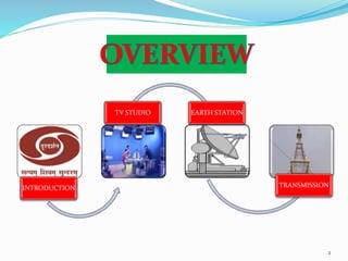
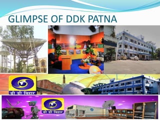
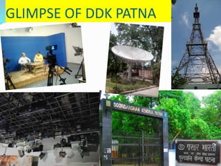
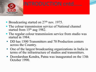
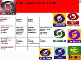
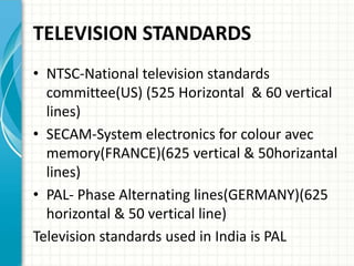
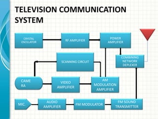
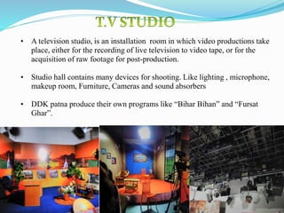
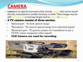
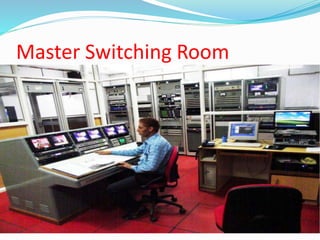
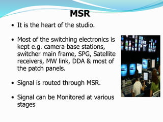
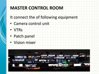
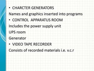
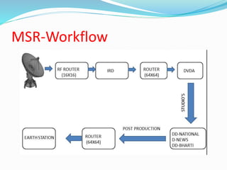
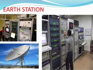
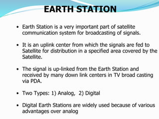
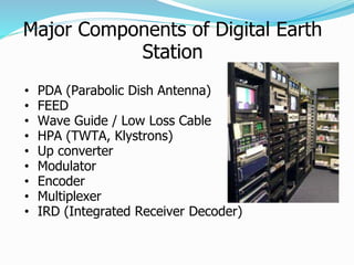
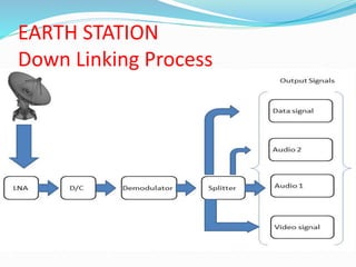
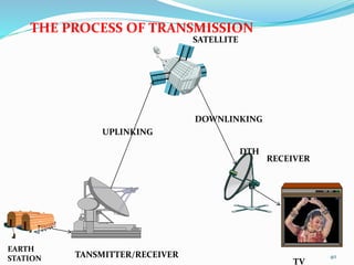
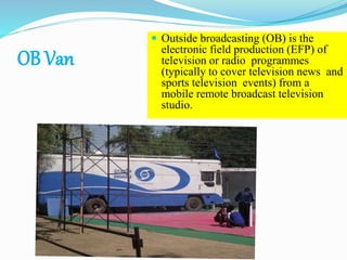
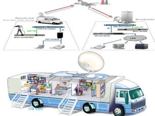
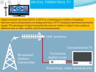
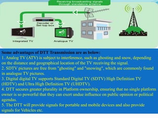
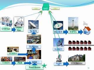
GOVERNMENT ENGINEERING
COLLEGE JHALAWAR
INDUSTRIAL TRAINING
FROM
DOORDARSHAN KENDRA, PATNA
ON TOPIC
TELEVISION BROADCAST SYSTEM
SUBMITTED BY:-
RAVI SHANKAR KUMAR
B.TECH (FINAL YEAR)
ROLL NO- 14EEJEC014
INTRODUCTION
TV STUDIO EARTH STATION
TRANSMISSION
2
CONTENTS
 GLIMPSE OF DDK PATNA
 INTRODUCTION
 TELEVISION STANDARDS
 FUNDAMENTALS OF TELEVISION SYSTEM
 TV STUDIO
 MSR
 EARTH STATION
 OB VAN
 ANTEENA & SATELLITE
 TRANSMITTER
 DD FREE DISH TV
 DIGITAL TERRESTRIAL TV
GLIMPSE OF DDK PATNA
INTRODUCTION
 Process of sending information to a distant place is
called Broadcasting.
 DOORDARSHAN = Distant + Show
 Means of Broadcasting in India:
1.Terrestrial.
2.Satellite.
3.Internet.
 Both AIR and DD make use of both Terrestrial and
Satellite.
 Doordarshan is a public broadcast terrestrial
Channel run by Prasar bharati.
INTRODUCTION cntd……
 Broadcasting started on 27th nov. 1975.
 The colour transmission service of National channel
started from 15th aug 1982.
 The regular colour transmission service from studio was
started in 1984.
 DD has 1500 Transmitters and 70 Production centers
across the Country.
 One of the largest broadcasting organizations in India in
terms of the infrastructure of studios and transmitters.
 Doordarshan Kendra, Patna was inaugurated on the 13th
October 1990.
DOORDARSHAN NETWORK
TELEVISION STANDARDS
• NTSC-National television standards
committee(US) (525 Horizontal & 60 vertical
lines)
• SECAM-System electronics for colour avec
memory(FRANCE)(625 vertical & 50horizantal
lines)
• PAL- Phase Alternating lines(GERMANY)(625
horizontal & 50 vertical line)
Television standards used in India is PAL
PAL ENCODER & DECODER
• Input is the primary colour (i.e. red, green,
blue) into matrix circuit as Y, R-Y, B-Y.
• Y=0.30R+0.59G+.11B
• U=0.477(R-Y)
• V=0.895(B-Y)
• Out of 625 horizontal line only 575 are active
• 50 vertical lines
FUNDAMENTALS OF TELEVISION SYSTEM
PICTURE
FORMATION
GREY SCALE
AND
BRIGHTNESS
RESOLUTION
CONTRAST
PICTURE FORMATION
 SCANNING
RESOLUTION
 CAPABILITY TO RESOLVE MAX. PIXELS ALONG SCANNING
LINES
 VERTICAL RESOLUTION DEPENDS ON NO. OF SCANNING
LINES
GREYSCALE AND BRIGHTNESS
• MIXING OF BLACK AND WHITE AT A CONTRAST RATIO OF
20:1
• BRIGHTNESS = ILLUMINATION OF REPRODUCED IMAGE
• CAN BE CONTROLLED BY ADJUSTING VOLTAGE BETWEEN
GRID AND CATHODE
CONTRAST
• RELATIVE DIFFERENCE BETWEEN BLACK AND WHITE
• CONTROLLED BY ADJUSTING SIGNAL FED TO PICTURE
TUBE
COLOUR COMPOSITE VIDEO
SIGNAL(CCVS)
SYNC PULSES BLANKING
SIGNALS
ADDITIONAL
SIGNALS
SCANNING
SIGNAL
ADDITIONAL
SIGNALS
CCVS
COLOUR COMPOSITE VIDEO SIGNAL
• Front porch is to crate horizontal blanking
Also contain sync pulse
• Back porch is the portion of each scan line
between end of horizontal sync pulse and
start of active video signal
• Colour burst is absent in the black and white
transmission of video signal
TELEVISION COMMUNICATION
SYSTEM
AUDIO
AMPLIFIER
FM MODULATOR
FM SOUND
TRANSMITTER
MIC.
CRYSTAL
OSCILLATOR RF AMPLIFIER
POWER
AMPLIFIER
SCANNING CIRCUIT
COMBINING
NETWORK
DEPLEXER
CAME
RA
VIDEO
AMPLIFIER
AM
MODULATION
AMPLIFIER
ADDITIVE COLOUR
MIXING
Y = 0.3 R + 0.59 G + 0.11 B
19
• A television studio, is an installation room in which video productions take
place, either for the recording of live television to video tape, or for the
acquisition of raw footage for post-production.
• Studio hall contains many devices for shooting. Like lighting , microphone,
makeup room, Furniture, Cameras and sound absorbers
• DDK patna produce their own programs like “Bihar Bihan” and “Fursat
Ghar”.
Components of TV studio
• Camera
• Lighting
• Microphones
• Vision mixer and Audio consoles
• MSR
• VTR
• Acoustics
• Post production and video effects
• Supporting services like AC, UPS
20
CAMERA
 camera is an optical instrument that records images that can be stored
directly, transmitted to another location, or both. These images may be
still photographs or moving images such as videos or movies.
 A TV camera consist of three section.
 Optical part - To form optical image.
 Transducer - To convert optical image in to electrical signal.
 Electronic part - To process output of a transducer to get a
CCVS ( colour composite video signal).
 CCD Camera are used for recording.
21
Types
 Hard lighting
 Soft lighting
Use gels to control the which in
beyond control to match it.
Never avoid the lighting
mismatch
TYPE
INTENSITY OF
LIGHTING
KEY LIGHT 100%
FILL LIGHT 80%
BACK LIGHT 110%
Sound is important for establishing mood and
intensifying an event
The sound track helps us to connect the visual
fragments of the relatively small, low-definition
television image to form a meaningful whole
Major types
 Dynamic/moving coil
microphones
 Condenser microphones
 Ribbon/velocity microphones
VISION MIXER
• A vision mixer (also called video
switcher, video mixer or production
switcher) is a device used to select
between several different video sources and
in some cases mix video sources together
and add special effects.
• It has many input sources such as cameras,
VCR/ server, Graphics/Character
Generators,etc.
• Out of these input, any source can be taken
as output.
• Sources can be changed as cut to cut,
dissolve, wipe and other special effects.
TYPICAL VIDEO CHAIN
TYPICAL AUDIO CHAIN
DistributorVision Mixer LOGO
Generator
Earth station
through
Optical Fiber
STL
Link
Sources
DistributorAudio Console
Analog to
AES
Converter
Earth station
through
Optical Fiber
Sources
STL Link
PRODUCTION CONTROL ROOM
• MONITOR
PROGRAM AND
GRAPHICS
• VISION MIXER
(to select video
sources)
• Audio console
• Add video
effect
Master Switching Room
MSR
• It is the heart of the studio.
• Most of the switching electronics is
kept e.g. camera base stations,
switcher main frame, SPG, Satellite
receivers, MW link, DDA & most of
the patch panels.
• Signal is routed through MSR.
• Signal can be Monitored at various
stages
MASTER CONTROL ROOM
It connect the of following equipment
• Camera control unit
• VTRs
• Patch panel
• Vision mixer
• CHARCTER GENERATORS
Names and graphics inserted into programs
• CONTROL APPARATUS ROOM
Includes the power supply unit
UPS room
Generator
• VIDEO TAPE RECORDER
Consists of recorded materials i.e. v.c.r
MSR-Workflow
Acoustic System
34
 It is derived from a Greek word “akoustos” which means
“hearing”.
It is use to prevent sounds from it’s echo.
In Doordarshan studio , all the sound must have to be
done Acoustic treatment to preserve the originality of the
sound along with extending maximum pleasure to the
listener.
EARTH STATION
EARTH STATION
• Earth Station is a very important part of satellite
communication system for broadcasting of signals.
• It is an uplink center from which the signals are fed to
Satellite for distribution in a specified area covered by the
Satellite.
• The signal is up-linked from the Earth Station and
received by many down link centers in TV broad casting
via PDA.
• Two Types: 1) Analog, 2) Digital
• Digital Earth Stations are widely used because of various
advantages over analog.
Major Components of Digital Earth
Station
• PDA (Parabolic Dish Antenna)
• FEED
• Wave Guide / Low Loss Cable
• HPA (TWTA, Klystrons)
• Up converter
• Modulator
• Encoder
• Multiplexer
• IRD (Integrated Receiver Decoder)
EARTH STATION
Up linking process
EARTH STATION
Down Linking Process
EARTH
STATION TANSMITTER/RECEIVER
SATELLITE
DTH
RECEIVER
TV
UPLINKING
DOWNLINKING
THE PROCESS OF TRANSMISSION
40
OB Van
 Outside broadcasting (OB) is the
electronic field production (EFP) of
television or radio programmes
(typically to cover television news and
sports television events) from a
mobile remote broadcast television
studio.
41
OB VAN
OB Van & DSNG
• A typical OB Van is usually
divided into 4 parts.
• The first and largest part is the
production area or sitting area
for all directors & producers.
• The second part of a van is for
the audio engineer.
• The 3rd part of the van is video
tape.
• The 4th part is transmission where the signal is monitored
by and engineered for quality control purposes and is
transmitted or sent to other trucks.
• DSNG is a portable uplinking centre.
Block diagram of OB Van
45
46
ANTENNA & SATELLITE
• An antenna (or aerial) is a transducer
designed to transmit or receive
electromagnetic waves. In other words,
antennas convert electromagnetic
waves into electrical currents and vice
versa.
TYPES
• Isotropic antenna (idealized)
o Radiates power equally in all directions.
• Dipole antennas-
o Half-wave dipole antenna (or Hertz
antenna)
o Quarter-wave vertical antenna (or
Marconi antenna)
• Parabolic Dish / Reflective Antenna
TRANSMITTER
 Aid of antenna
 Produces radio wave
 Connect earth station
to satellites
 Also connect
television
TRANSMITTER
 A television transmitter is a
device which broadcasts
an electromagnetic signal to
the television receivers.
 Television transmitters may
be analog or digital.
 Types of Transmitters
 (1)VLPT’s
 (2)LPT’s
 (3)HPT’s
 DDK Patna Has 6 HPT’s, 24
LPT’s ,2 VLPT’s.
50
DD Free Dish is India's only Free Direct-To-Home Service previously
known as DD Direct +. This service was launched in December,
2004. DD Free Dish DTH service is owned and operated by Public
Service Broadcaster Prasar Bharati (Doordarshan).
DIGITAL TERRESTRIAL TV
Digital terrestrial television (DTTV or DTT) is a technological evolution of broadcast
television and an advancement over analog television. DTTV broadcasts land-based (terrestrial)
signals. The advantages of digital terrestrial television are similar to digital versus analog in
platforms such as cable, satellite, and all telecommunications
Some advantages of DTT Transmission are as below:
1. Analog TV (ATV) is subject to interference, such as ghosting and snow, depending
on the distance and geographical location of the TV receiving the signal.
2. SDTV pictures are free from "ghosting" and "snowing", which are commonly found
in analogue TV pictures.
3. Digital digital TV supports Standard Digital TV (SDTV) High Definition TV
(HDTV) and Ultra High Definition TV (UHDTV).
4. DTT secures greater plurality in Platform ownership, ensuring that no single platform
owner is so powerful that they can exert undue influence on public opinion or political
agendas.
5. The DTT will provide signals for portable and mobile devices and also provide
signals for Vehicles etc.
54
T V STUDIO PCR
Tx Room
MSR
Tx E/S
DTH Service
O B Van
DSNG
Van
Rx cable TV
Rx E/S H P Tx
Rx dish
TV
DD Archives
SAT
Feed Room
55
DOORDARSHAN KENDRA PATNA SUMMER TRAINING

DOORDARSHAN KENDRA PATNA SUMMER TRAINING

  • 1.
    GOVERNMENT ENGINEERING COLLEGE JHALAWAR INDUSTRIALTRAINING FROM DOORDARSHAN KENDRA, PATNA ON TOPIC TELEVISION BROADCAST SYSTEM SUBMITTED BY:- RAVI SHANKAR KUMAR B.TECH (FINAL YEAR) ROLL NO- 14EEJEC014
  • 2.
    INTRODUCTION TV STUDIO EARTHSTATION TRANSMISSION 2
  • 3.
    CONTENTS  GLIMPSE OFDDK PATNA  INTRODUCTION  TELEVISION STANDARDS  FUNDAMENTALS OF TELEVISION SYSTEM  TV STUDIO  MSR  EARTH STATION  OB VAN  ANTEENA & SATELLITE  TRANSMITTER  DD FREE DISH TV  DIGITAL TERRESTRIAL TV
  • 4.
  • 5.
  • 6.
    INTRODUCTION  Process ofsending information to a distant place is called Broadcasting.  DOORDARSHAN = Distant + Show  Means of Broadcasting in India: 1.Terrestrial. 2.Satellite. 3.Internet.  Both AIR and DD make use of both Terrestrial and Satellite.  Doordarshan is a public broadcast terrestrial Channel run by Prasar bharati.
  • 7.
    INTRODUCTION cntd……  Broadcastingstarted on 27th nov. 1975.  The colour transmission service of National channel started from 15th aug 1982.  The regular colour transmission service from studio was started in 1984.  DD has 1500 Transmitters and 70 Production centers across the Country.  One of the largest broadcasting organizations in India in terms of the infrastructure of studios and transmitters.  Doordarshan Kendra, Patna was inaugurated on the 13th October 1990.
  • 8.
  • 9.
    TELEVISION STANDARDS • NTSC-Nationaltelevision standards committee(US) (525 Horizontal & 60 vertical lines) • SECAM-System electronics for colour avec memory(FRANCE)(625 vertical & 50horizantal lines) • PAL- Phase Alternating lines(GERMANY)(625 horizontal & 50 vertical line) Television standards used in India is PAL
  • 10.
    PAL ENCODER &DECODER • Input is the primary colour (i.e. red, green, blue) into matrix circuit as Y, R-Y, B-Y. • Y=0.30R+0.59G+.11B • U=0.477(R-Y) • V=0.895(B-Y) • Out of 625 horizontal line only 575 are active • 50 vertical lines
  • 11.
    FUNDAMENTALS OF TELEVISIONSYSTEM PICTURE FORMATION GREY SCALE AND BRIGHTNESS RESOLUTION CONTRAST
  • 12.
  • 13.
    RESOLUTION  CAPABILITY TORESOLVE MAX. PIXELS ALONG SCANNING LINES  VERTICAL RESOLUTION DEPENDS ON NO. OF SCANNING LINES GREYSCALE AND BRIGHTNESS • MIXING OF BLACK AND WHITE AT A CONTRAST RATIO OF 20:1 • BRIGHTNESS = ILLUMINATION OF REPRODUCED IMAGE • CAN BE CONTROLLED BY ADJUSTING VOLTAGE BETWEEN GRID AND CATHODE CONTRAST • RELATIVE DIFFERENCE BETWEEN BLACK AND WHITE • CONTROLLED BY ADJUSTING SIGNAL FED TO PICTURE TUBE
  • 14.
    COLOUR COMPOSITE VIDEO SIGNAL(CCVS) SYNCPULSES BLANKING SIGNALS ADDITIONAL SIGNALS SCANNING SIGNAL ADDITIONAL SIGNALS CCVS
  • 15.
  • 16.
    • Front porchis to crate horizontal blanking Also contain sync pulse • Back porch is the portion of each scan line between end of horizontal sync pulse and start of active video signal • Colour burst is absent in the black and white transmission of video signal
  • 17.
    TELEVISION COMMUNICATION SYSTEM AUDIO AMPLIFIER FM MODULATOR FMSOUND TRANSMITTER MIC. CRYSTAL OSCILLATOR RF AMPLIFIER POWER AMPLIFIER SCANNING CIRCUIT COMBINING NETWORK DEPLEXER CAME RA VIDEO AMPLIFIER AM MODULATION AMPLIFIER
  • 18.
    ADDITIVE COLOUR MIXING Y =0.3 R + 0.59 G + 0.11 B
  • 19.
    19 • A televisionstudio, is an installation room in which video productions take place, either for the recording of live television to video tape, or for the acquisition of raw footage for post-production. • Studio hall contains many devices for shooting. Like lighting , microphone, makeup room, Furniture, Cameras and sound absorbers • DDK patna produce their own programs like “Bihar Bihan” and “Fursat Ghar”.
  • 20.
    Components of TVstudio • Camera • Lighting • Microphones • Vision mixer and Audio consoles • MSR • VTR • Acoustics • Post production and video effects • Supporting services like AC, UPS 20
  • 21.
    CAMERA  camera isan optical instrument that records images that can be stored directly, transmitted to another location, or both. These images may be still photographs or moving images such as videos or movies.  A TV camera consist of three section.  Optical part - To form optical image.  Transducer - To convert optical image in to electrical signal.  Electronic part - To process output of a transducer to get a CCVS ( colour composite video signal).  CCD Camera are used for recording. 21
  • 22.
    Types  Hard lighting Soft lighting Use gels to control the which in beyond control to match it. Never avoid the lighting mismatch
  • 23.
    TYPE INTENSITY OF LIGHTING KEY LIGHT100% FILL LIGHT 80% BACK LIGHT 110%
  • 24.
    Sound is importantfor establishing mood and intensifying an event The sound track helps us to connect the visual fragments of the relatively small, low-definition television image to form a meaningful whole
  • 25.
    Major types  Dynamic/movingcoil microphones  Condenser microphones  Ribbon/velocity microphones
  • 26.
    VISION MIXER • Avision mixer (also called video switcher, video mixer or production switcher) is a device used to select between several different video sources and in some cases mix video sources together and add special effects. • It has many input sources such as cameras, VCR/ server, Graphics/Character Generators,etc. • Out of these input, any source can be taken as output. • Sources can be changed as cut to cut, dissolve, wipe and other special effects.
  • 27.
    TYPICAL VIDEO CHAIN TYPICALAUDIO CHAIN DistributorVision Mixer LOGO Generator Earth station through Optical Fiber STL Link Sources DistributorAudio Console Analog to AES Converter Earth station through Optical Fiber Sources STL Link
  • 28.
    PRODUCTION CONTROL ROOM •MONITOR PROGRAM AND GRAPHICS • VISION MIXER (to select video sources) • Audio console • Add video effect
  • 29.
  • 30.
    MSR • It isthe heart of the studio. • Most of the switching electronics is kept e.g. camera base stations, switcher main frame, SPG, Satellite receivers, MW link, DDA & most of the patch panels. • Signal is routed through MSR. • Signal can be Monitored at various stages
  • 31.
    MASTER CONTROL ROOM Itconnect the of following equipment • Camera control unit • VTRs • Patch panel • Vision mixer
  • 32.
    • CHARCTER GENERATORS Namesand graphics inserted into programs • CONTROL APPARATUS ROOM Includes the power supply unit UPS room Generator • VIDEO TAPE RECORDER Consists of recorded materials i.e. v.c.r
  • 33.
  • 34.
    Acoustic System 34  Itis derived from a Greek word “akoustos” which means “hearing”. It is use to prevent sounds from it’s echo. In Doordarshan studio , all the sound must have to be done Acoustic treatment to preserve the originality of the sound along with extending maximum pleasure to the listener.
  • 35.
  • 36.
    EARTH STATION • EarthStation is a very important part of satellite communication system for broadcasting of signals. • It is an uplink center from which the signals are fed to Satellite for distribution in a specified area covered by the Satellite. • The signal is up-linked from the Earth Station and received by many down link centers in TV broad casting via PDA. • Two Types: 1) Analog, 2) Digital • Digital Earth Stations are widely used because of various advantages over analog.
  • 37.
    Major Components ofDigital Earth Station • PDA (Parabolic Dish Antenna) • FEED • Wave Guide / Low Loss Cable • HPA (TWTA, Klystrons) • Up converter • Modulator • Encoder • Multiplexer • IRD (Integrated Receiver Decoder)
  • 38.
  • 39.
  • 40.
  • 41.
    OB Van  Outsidebroadcasting (OB) is the electronic field production (EFP) of television or radio programmes (typically to cover television news and sports television events) from a mobile remote broadcast television studio. 41
  • 42.
  • 43.
    OB Van &DSNG • A typical OB Van is usually divided into 4 parts. • The first and largest part is the production area or sitting area for all directors & producers. • The second part of a van is for the audio engineer. • The 3rd part of the van is video tape.
  • 44.
    • The 4thpart is transmission where the signal is monitored by and engineered for quality control purposes and is transmitted or sent to other trucks. • DSNG is a portable uplinking centre.
  • 45.
  • 46.
  • 47.
    ANTENNA & SATELLITE •An antenna (or aerial) is a transducer designed to transmit or receive electromagnetic waves. In other words, antennas convert electromagnetic waves into electrical currents and vice versa.
  • 48.
    TYPES • Isotropic antenna(idealized) o Radiates power equally in all directions. • Dipole antennas- o Half-wave dipole antenna (or Hertz antenna) o Quarter-wave vertical antenna (or Marconi antenna) • Parabolic Dish / Reflective Antenna
  • 49.
    TRANSMITTER  Aid ofantenna  Produces radio wave  Connect earth station to satellites  Also connect television
  • 50.
    TRANSMITTER  A televisiontransmitter is a device which broadcasts an electromagnetic signal to the television receivers.  Television transmitters may be analog or digital.  Types of Transmitters  (1)VLPT’s  (2)LPT’s  (3)HPT’s  DDK Patna Has 6 HPT’s, 24 LPT’s ,2 VLPT’s. 50
  • 51.
    DD Free Dishis India's only Free Direct-To-Home Service previously known as DD Direct +. This service was launched in December, 2004. DD Free Dish DTH service is owned and operated by Public Service Broadcaster Prasar Bharati (Doordarshan).
  • 52.
    DIGITAL TERRESTRIAL TV Digitalterrestrial television (DTTV or DTT) is a technological evolution of broadcast television and an advancement over analog television. DTTV broadcasts land-based (terrestrial) signals. The advantages of digital terrestrial television are similar to digital versus analog in platforms such as cable, satellite, and all telecommunications
  • 53.
    Some advantages ofDTT Transmission are as below: 1. Analog TV (ATV) is subject to interference, such as ghosting and snow, depending on the distance and geographical location of the TV receiving the signal. 2. SDTV pictures are free from "ghosting" and "snowing", which are commonly found in analogue TV pictures. 3. Digital digital TV supports Standard Digital TV (SDTV) High Definition TV (HDTV) and Ultra High Definition TV (UHDTV). 4. DTT secures greater plurality in Platform ownership, ensuring that no single platform owner is so powerful that they can exert undue influence on public opinion or political agendas. 5. The DTT will provide signals for portable and mobile devices and also provide signals for Vehicles etc.
  • 54.
    54 T V STUDIOPCR Tx Room MSR Tx E/S DTH Service O B Van DSNG Van Rx cable TV Rx E/S H P Tx Rx dish TV DD Archives SAT Feed Room
  • 55.

Editor's Notes

  • #29 Use a section header for each of the topics, so there is a clear transition to the audience.
  • #32 Add slides to each topic section as necessary, including slides with tables, graphs, and images. See next section for sample table, graph, image, and video layouts.
  • #33 Keep it brief. Make your text as brief as possible to maintain a larger font size.
  • #50 Discuss outcomes of the case study or class simulation. Cover best practices.