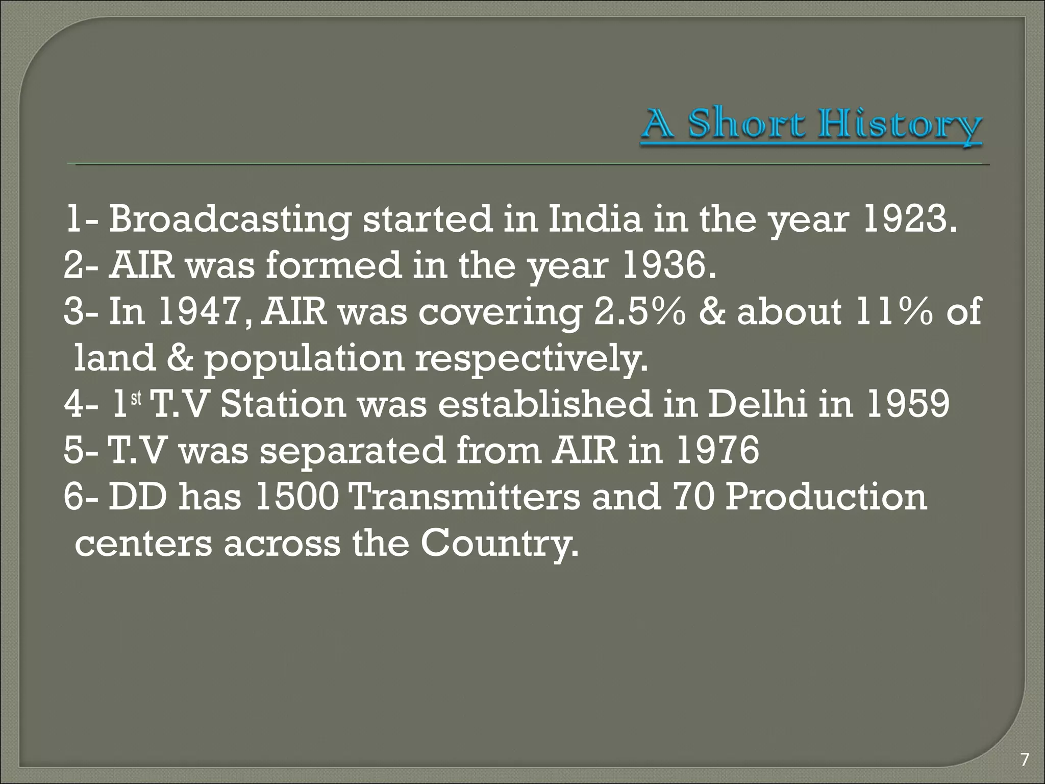
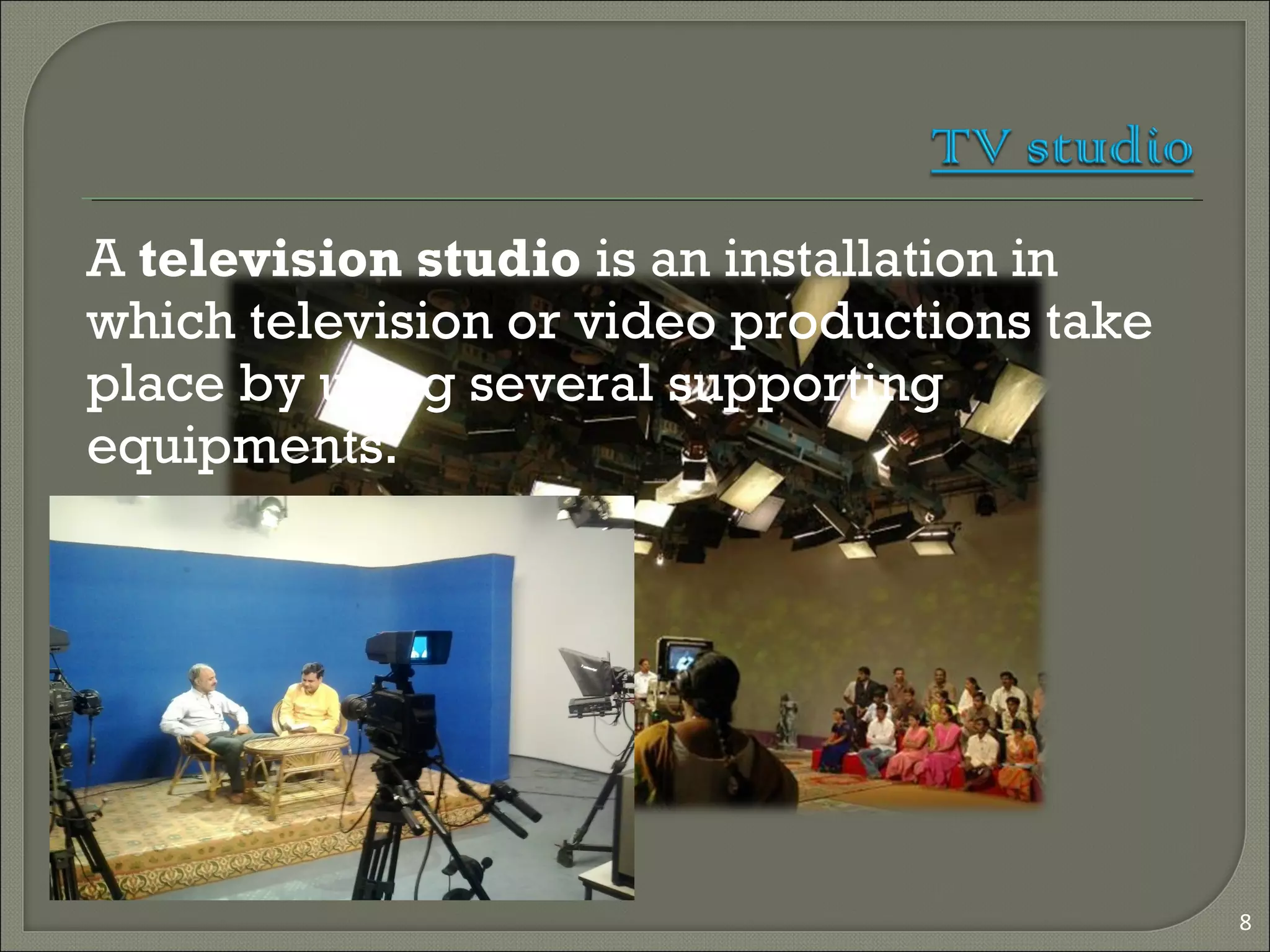
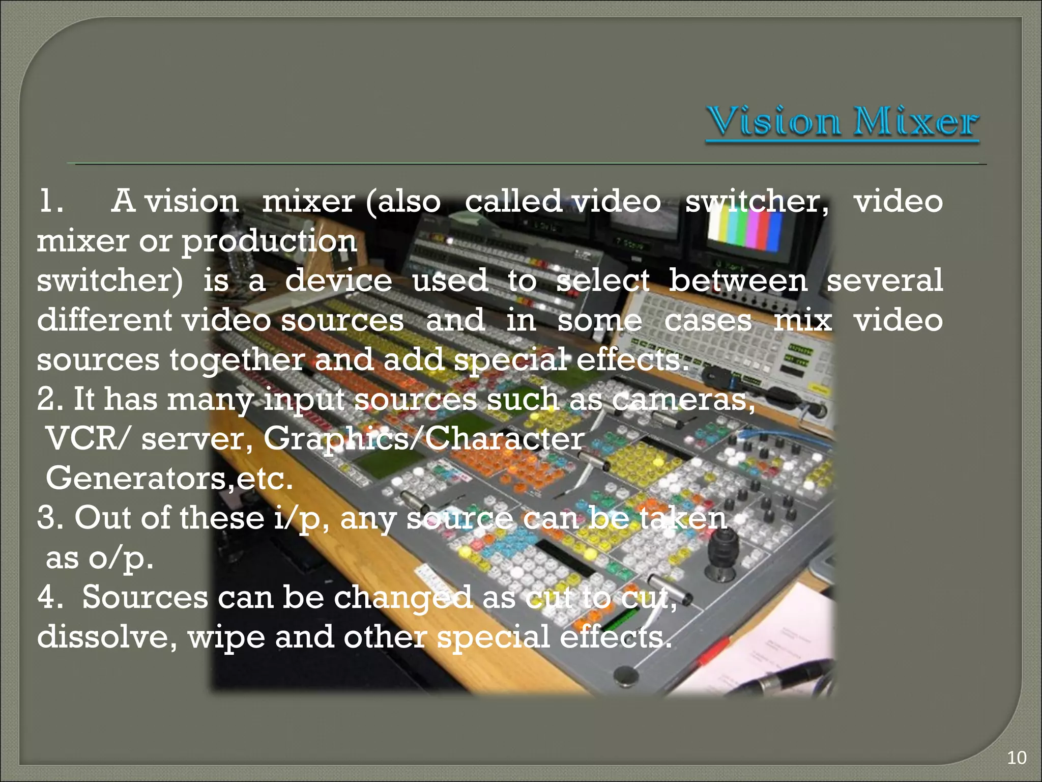
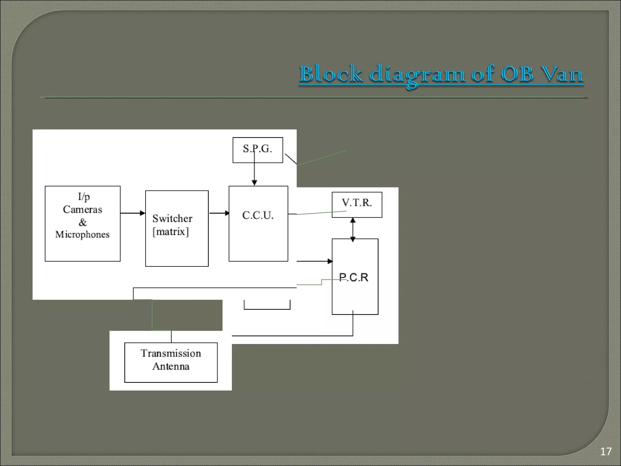
1
Submitted by
Ishrat hashmi
1303531028
ECE 4th
year
1. Recent Scenario Of Electronic Media
2. Television In Day To Day Life
3. Glimpse Of Training Program at DDK Muzaffarpur
4. Introduction
5. A Short History
6. TV Studio
7. Vision mixer
8. Audio & video chain
9.MSR
10.Earth station
11.OB VAN & DSNG
2
3
Recent Scenario of Electronics
Entertainment Media
Interne
t
DTH
Personal
Computers/
Smartphones
Cinema
Hall
Radio
Television
4
5
Broadcasting:
Process of sending information to a
distant place is called Broadcasting.
Means of Broadcasting in India:
1.Terrestrial
2.Satellite
3.Internet
Both AIR & DD make use of both
Terrestrial & satellite.
6
1- Broadcasting started in India in the year 1923.
2- AIR was formed in the year 1936.
3- In 1947, AIR was covering 2.5% & about 11% of
land & population respectively.
4- 1st
T.V Station was established in Delhi in 1959
5- T.V was separated from AIR in 1976
6- DD has 1500 Transmitters and 70 Production
centers across the Country.
7
8
A television studio is an installation in
which television or video productions take
place by using several supporting
equipments.
Camera
Lighting
Microphones
Vision mixer and Audio consoles
MSR
VTR
Acoustics
Post production and video effects
Supporting services like AC, UPS
9
10
1. A vision mixer (also called video switcher, video
mixer or production
switcher) is a device used to select between several
different video sources and in some cases mix video
sources together and add special effects.
2. It has many input sources such as cameras,
VCR/ server, Graphics/Character
Generators,etc.
3. Out of these i/p, any source can be taken
as o/p.
4. Sources can be changed as cut to cut,
dissolve, wipe and other special effects.
11
1-Use PAL system (720*576) in 4:3 aspect ratio.
2-For TV Transmission It uses VSM .
3-It Uses C Band( DTH uses Ku band) and in the transmitter room it
has two 10 KW Transmitters for Broadcasting.
12
Distributor
Audio
Console
Analog to
AES
Converter
Earth station
through
Optical Fiber
STL Link
Sources
It is the heart of the studio.
Most of the switching
electronics is kept e.g.
camera base stations,
switcher main frame,
Satellite receivers, MW
link, DDA & most of the
patch panels.
Signal is routed through
MSR.
Signal can be Monitored at
various stages
13
14
Earth Station is a very important part of satellite
communication system for broadcasting of
signals.
It is an uplink center from which the signals are
fed to Satellite for distribution in a specified area
covered by the Satellite.
The signal is up-linked from the Earth Station
and received by many down link centers in TV
broad casting via PDA.
Two Types:
1) Analog
2) Digital
Digital Earth Stations are widely used because
of various advantages over analog.
15
• PDA (Parabolic Dish
Antenna)
• FEED
• Wave Guide / Low Loss
Cable
• Up converter
• Modulator
• Encoder
• Multiplexer
• IRD (Integrated Receiver
Decoder)
Outside broadcasting (OB) is the electronic field production (EFP) of
television or radio programmes (typically to cover television news and sports
television events) from a mobile remote broadcast television studio.
16
17
A typical OB Van is usually divided into 4 parts.
The first and largest part is the production area or sitting area
for all directors & producers.
The second part of a van is for the audio engineer.
The 3rd part of the van is video tape
The 4th part is transmission where the signal is monitored by
and engineered for quality control purposes and is
transmitted.
18
If there is a live program to be telecast following
options can be choosed.
Microwave link
DSNG (digital satellite news gathering)
19
 Audio and video signals are feed to micowave transmitter.
 Input video is processed and up converted to 12.25 & 12.30 GHz.
 Approx transmission power is 600 milli watts
 Transmit/ receive station is 1.1 m in diameter.
 Audio/ video input is
processed by an encoder as
per mpeg-2 standard.
 The audio and video along
with other data are
multiplied.
 Multiplied data forward error
corrected using a standard
technique.
 Error corrected codes are
QPSK modulated at 70 MHz.
 The modulated signal is up
converted to power
amplifiers.
20
21
Conclusion
1-Overall a very nice experience
2-Learn about Team work power.
3- Practically watched how studio
recording take place.
Thank you…
22
Any queries ?

Ppt ddk

  • 1.
  • 2.
    1. Recent ScenarioOf Electronic Media 2. Television In Day To Day Life 3. Glimpse Of Training Program at DDK Muzaffarpur 4. Introduction 5. A Short History 6. TV Studio 7. Vision mixer 8. Audio & video chain 9.MSR 10.Earth station 11.OB VAN & DSNG 2
  • 3.
    3 Recent Scenario ofElectronics Entertainment Media Interne t DTH Personal Computers/ Smartphones Cinema Hall Radio Television
  • 4.
  • 5.
  • 6.
    Broadcasting: Process of sendinginformation to a distant place is called Broadcasting. Means of Broadcasting in India: 1.Terrestrial 2.Satellite 3.Internet Both AIR & DD make use of both Terrestrial & satellite. 6
  • 7.
    1- Broadcasting startedin India in the year 1923. 2- AIR was formed in the year 1936. 3- In 1947, AIR was covering 2.5% & about 11% of land & population respectively. 4- 1st T.V Station was established in Delhi in 1959 5- T.V was separated from AIR in 1976 6- DD has 1500 Transmitters and 70 Production centers across the Country. 7
  • 8.
    8 A television studio is aninstallation in which television or video productions take place by using several supporting equipments.
  • 9.
    Camera Lighting Microphones Vision mixer andAudio consoles MSR VTR Acoustics Post production and video effects Supporting services like AC, UPS 9
  • 10.
    10 1. A vision mixer (alsocalled video switcher, video mixer or production switcher) is a device used to select between several different video sources and in some cases mix video sources together and add special effects. 2. It has many input sources such as cameras, VCR/ server, Graphics/Character Generators,etc. 3. Out of these i/p, any source can be taken as o/p. 4. Sources can be changed as cut to cut, dissolve, wipe and other special effects.
  • 11.
    11 1-Use PAL system(720*576) in 4:3 aspect ratio. 2-For TV Transmission It uses VSM . 3-It Uses C Band( DTH uses Ku band) and in the transmitter room it has two 10 KW Transmitters for Broadcasting.
  • 12.
  • 13.
    It is theheart of the studio. Most of the switching electronics is kept e.g. camera base stations, switcher main frame, Satellite receivers, MW link, DDA & most of the patch panels. Signal is routed through MSR. Signal can be Monitored at various stages 13
  • 14.
    14 Earth Station isa very important part of satellite communication system for broadcasting of signals. It is an uplink center from which the signals are fed to Satellite for distribution in a specified area covered by the Satellite. The signal is up-linked from the Earth Station and received by many down link centers in TV broad casting via PDA. Two Types: 1) Analog 2) Digital Digital Earth Stations are widely used because of various advantages over analog.
  • 15.
    15 • PDA (ParabolicDish Antenna) • FEED • Wave Guide / Low Loss Cable • Up converter • Modulator • Encoder • Multiplexer • IRD (Integrated Receiver Decoder)
  • 16.
    Outside broadcasting (OB)is the electronic field production (EFP) of television or radio programmes (typically to cover television news and sports television events) from a mobile remote broadcast television studio. 16
  • 17.
  • 18.
    A typical OBVan is usually divided into 4 parts. The first and largest part is the production area or sitting area for all directors & producers. The second part of a van is for the audio engineer. The 3rd part of the van is video tape The 4th part is transmission where the signal is monitored by and engineered for quality control purposes and is transmitted. 18 If there is a live program to be telecast following options can be choosed. Microwave link DSNG (digital satellite news gathering)
  • 19.
    19  Audio andvideo signals are feed to micowave transmitter.  Input video is processed and up converted to 12.25 & 12.30 GHz.  Approx transmission power is 600 milli watts  Transmit/ receive station is 1.1 m in diameter.
  • 20.
     Audio/ videoinput is processed by an encoder as per mpeg-2 standard.  The audio and video along with other data are multiplied.  Multiplied data forward error corrected using a standard technique.  Error corrected codes are QPSK modulated at 70 MHz.  The modulated signal is up converted to power amplifiers. 20
  • 21.
    21 Conclusion 1-Overall a verynice experience 2-Learn about Team work power. 3- Practically watched how studio recording take place.
  • 22.