SlideShare a Scribd company logo
1 of 6
Download to read offline
BASICS OF C & Ku BAND
TRANSMISSIONS & LNBs
A satellite broadcasts a few watts of microwave signals from the geostationary orbit 36,000
kilometers above the earth. The transmissions are also broadcast over a wide “footprint” area. The
satellite signals suffer an attenuation of approximately 200 dB, while making this 36,000 kilometer
journey from the satellite to reception points on the ground. The satellite signals which finally
arrive are extremely weak.
A dish antenna is used to collect these weak satellite signals over a large area - the surface of the
dish. These signals are then focussed by the parabolic curvature of the dish, to the focal point.
Even at the focal point, the satellite signals are only a few micro-watts.
These tiny satellite signals are received and processed by sophisticated electronic equipment.
Given the low signal strength, the signals need to be immediately amplified. However, it is very
important that the amplification does not contribute any significant amount of noise which would
otherwise spoil the weak signals received. This is done by a “Low Noise Amplifier” - LNA.
The LNA actually consist of 2 or 3 amplifying stages that boost the signal to a reasonable level at
which it can be further processed. The LNA is designed with an all out effort to keep noise down to
the barest minimum.
NOISE TEMPERATURE
The amount of noise added by the LNA to the received signal is indicated in terms of “Noise
Temperature”. Noise temperature is specified in degrees Kelvin. For all practical purposes, the
lower the noise temperature, the better is the LNA’s performance. Approximately 10 years ago, a
noise temperature of 24 degrees Kelvin was excellent performance for commercial units. However,
with today’s improved technology, extremely low noise units such as those from Eurostar, offer a
noise temperature of 17 deg. K.
Table 1 Indicates Equivalent Noise Specifications In Degrees Kelvin And dB.
NF (dB) T (K) NF (dB) T (K) NF (dB) T (K) NF (dB) T (K)
0.1 7 1.1 84 2.1 180 3.1 302
0.2 14 1.2 92 2.2 191 3.2 316
0.3 21 1.3 101 2.3 202 3.3 330
0.4 28 1.4 110 2.4 214 3.4 344
Page 1 of 6Satellite & Cable TV
The noise performance depends on the type of amplifying device used for the LNA stages. While C
Band LNBs use bipolar transistors, KU band LNBs use GaAsFET transistors for the initial
amplification. While it is customary to list the noise temperature for C Band LNBs, KU Band LNBs
usually specify their noise, not as a Noise Temperature, but as a Noise Figure, in dB. The dB
specification helps compute the total system noise, easily, but the more widespread use of a Noise
Figure in db, particularly for Ku Band LNBs probably helps in “specmanship” for marketing
purposes. KU band LNBs have much higher noise temperatures, which would not look good on
paper. Hence they are quoted in units that look deceptively low, viz dB.
C AND KU BANDS
The atmosphere provides a low loss signal path for certain microwave frequencies. Satellite
broadcasters therefore use this fact and provide satellite broadcasts at these frequencies. The
earliest broadcast were at relatively low microwave frequencies. Infact, India’s first rural education
satellite broadcast from the SITE satellite in 1975 were at UHF frequencies.
India’s first INSAT satellites offered Doordarshan TV broadcasts in the S Band at 2575 MHz & 2615
MHz. Even the INSAT 3C satellite launched on 24th Jan 2002 has 2 S-Band transponders. Most
subsequent broadcasts have been in the C Band and Extended C Band range of frequencies. Infact
India is the only country that has currently been licensed extended C Band frequencies for
commercial use.
The amount of signal that a dish receives is directly linked to the frequency. For the same size of
dish, the signals received will be larger for higher frequencies that lower frequencies. Technically,
this implies that the same dish has a larger “Gain” at higher frequencies. Similarly, a smaller dish
could be used at higher frequencies and yet provide the same signal gain. Recognising this,
international broadcasters now utilise Ku and even Ka band frequencies for commercial television
broadcast via satellite.
UPLINKING AND DOWNLINKING
A satellite receives television broadcast from
a ground station. This is termed as
“Uplinking” because the signals are sent up
from the ground to the satellite. These signals
are then broadcast down over the footprint
area in a process called “Downlinking”.
Uplinking and Downlinking are shown
graphically in Figure 1.
To ensure that the uplink and downlink
signals do not interfere with each other,
separate frequencies are used for uplinking
and downlinking. Table 2 indicates the S, C
and KU Bands for both uplinking and downlinking.
Table to convert Noise Figure (NF) in dB to Noise Temperature in deg. K
0.5 35 1.5 120 2.5 226 3.5 359
0.6 43 1.6 129 2.6 238 3.6 374
0.7 51 1.7 139 2.7 250 3.7 390
0.8 59 1.8 149 2.8 263 3.8 406
0.9 67 1.9 159 2.9 275 3.9 422
1.0 75 2.0 170 3.0 289 4.0 438
Page 2 of 6Satellite & Cable TV
THE LNB
After the C or KU band frequencies are amplified by the LNA, they need to be processed. The
processing is done in the satellite receiver which is usually located 10 meters to 50 meters away
from the dish antenna. Microwave signals in the S, C or KU Band would suffer very high
attenuation if they were carried via coaxial cable from the LNA to the Satellite Receiver 50 meters
away.
To overcome this problem, the microwave signals are converted to a block of frequencies from 950
MHz to 2150 MHz. Hence, incoming signals received by the LNA at 2 GHz, 4 GHz and even 12 GHz
are even block converted down to 950 MHz to 2150 MHz. This range of frequencies is referred to
as Intermediate Frequencies since their range of temporary or intermediate frequencies in the
chain of satellite reception which receives microwave signals and finally yields video and audio
signals from the satellite receiver. This function is carried out by a “Block Converter” located within
the LNB. A combination of Low Noise amplifier + Block converter is referred to as an LNB. A block
diagram of a commercial LNB is shown in Figure 2.
The Block Converter consists of 4 important sections as shown in Figure 2.
MIXER
The Block Converter uses the Hetrodyne
principle for conversion of a block of S, C or
KU Band frequencies to the IF or
Intermediate Frequencies. The Hetrodyne
principle mixes an external fixed frequency
with the incoming frequency. The output
from the mixer is a series of signals at the
sum and difference of the two inputs to the
mixer. Outputs are also produced at
multiples of these frequencies. A simple filter
is used to suppress all frequency components except those required.
LOCAL OSCILLATOR
The Local Oscillator (LO) is a section of the LNB and gets its name since it is present locally or
within the LNB. The local oscillator produces a fixed output at a pre-determined frequency. The
Local Oscillator (LO) frequencies have been standardised by LNB manufacturers worldwide for S,
C, Ku and even Ka band frequencies. The LO frequencies have been selected to yield an output in
the IF (950 MHz to 2150 MHz) range, for all types of LNBs. As a result, universal satellite receivers
can be designed for reception of C and KU Band signals through the same satellite receiver.
Table 2 : An Overview Of S, C, Ku & Ka Band Frequencies
DOWNLINK FREQ (GHz) UP-LINK FREQ (GHz)
S BAND 2.555 to 2.635 5.855 to 5.935
Extended C Band (Lower) 3.4 to 3.7 5.725 to 5.925
C Band 3.7 to 4.2 5.925 to 6.425
Extended C Band (Upper) 4.5 to 4.8 6.425 to 7.075
Ku Band 10.7 to 13.25 12.75 to 14.25
Ka Band 18.3 to 22.20 27.0 to 31.00
Table 3 - Local Oscillator Frequencies
Page 3 of 6Satellite & Cable TV
Table 3 lists the Local Oscillator frequencies for various LNBs. Do note that since S and Extended C
Band LNBs are not used universally, the local oscillator frequency indicated is typical but not an
international standard.
The output frequency is directly related to the local oscillator frequency. Hence it is very important
to have an extremely stable (fixed) local oscillator frequency. To ensure this, most LNBs utilise a
crystal oscillator for the LO. This ensures that the LO frequency does not change either with the
Input voltage to the LNB or due to temperature changes that the LNB is exposed to. Keep in mind
that the LNB is mounted outdoors and is often subjected to sub-zero temperatures with high wind
velocities or high ambient temperatures when directly exposed to sunlight in tropical climates such
as India.
SAMPLE CALCULATION
To further illustrate the relevance of a Local Oscillator frequency, let us consider the case of typical
C Band reception. The C Band LNB is designed to receive satellite broadcast from 3,800 MHz to
4,200 MHz. The LO within the LNB is standardised at 5150 MHz.
Hence when receiving a broadcast at 3,800 MHz, the output frequency of interest is
5150 - 3800 = 1350 MHz
Similarly, when receiving a broadcast at 4,200 MHz, the output frequency of interest is
5150 - 4200 = 950 MHz
We see that both these output signals viz. at 1350 MHz and 950 MHz lie in the standard IF
frequency band that satellite receivers accept.
For extended C Band reception, the LO frequency is increased to 5950 MHz so that the output
continues to fall within the IF range.
In the case of KU Band LNBs, the local oscillator frequency is actually less than the KU band signal.
However the LO frequency is chosen so that the difference always lies in the IF frequency range
for satellite receivers.
FILTER
As shown in the LNB Block diagram Figure 2, Bandpass Filters are introduced both before and after
the mixer. The filters after the mixer suppress or filter out all frequencies except the required
frequency which is the difference between the microwave broadcast and the local oscillator
frequency.
Reception Freq. L.O. Freq. Output Freq.
2.5 to 2.7 3.65 950 to 1150
3.4 to 4.2 5.15 950 to 1750
4.5 to 4.8 5.95 950 to 1250
10.7 to 11.8 9.75 950 to 2050
10.95 to 11.70 10.0 950 to 1700
11.7 to 12.5 10.6 / 10.75 950 to 1750
12.25 to 12.75 10.6 / 10.75 950 to 1450
12.25 to 12.75 11.3 950 to 1450
12.5 to 12.75 11.475 1025 to 1275
Page 4 of 6Satellite & Cable TV
THE KU BAND
The KU Band actually used for downlinking spans a wide range of frequencies viz. 10.7 GHz to
12.75 GHz. 1 GHz = 1,000 MHz. This wide range of KU Band frequencies cannot be handled by a
single local oscillator frequency. Initial KU Band reception was at 10.7 GHz to 11.8 GHz. The LNBs
then utilised a LO of 9.75 GHz.
Table 3 indicates various KU Band segments and local oscillator frequencies used to receive these
signals.
IF AMPLIFIERS
The output of the mixer is an IF signal, at a fairly low level. Since this signal is of a specific
bandwidth only, it can be easily amplified, significantly. An LNB often includes atleast 2 stages of
IF amplification. This amplified signal is then filtered and fed to the output via a DC blocking
capacitor. The capacitor allows the signal to pass through but steers the power coming from the
satellite receiver, to the LNB power supply.
UNIVERSAL LNB
KU Band LNBs today effectively split the KU band into 2 frequency segments and utilise separate
local oscillators for each of these frequency segments. As an example, the COLORADO Universal
LNB receives satellite transmissions from 10.7 GHz to 12.75 GHz. For the lower frequency band,
the local oscillator operates at 9.75 GHz. For the upper frequency band, the local oscillator
operates at 10.6 GHz, or sometimes 10.75 GHz.
The necessary Local Oscillator is activated by send the LNB a burst of 22 KHz signals, from the
satellite receiver. When the Satellite receiver is told by the user to tune into a Satellite Channel
between 11.7 GHz to 12.75 GHz, the 10.6 GHz local oscillator is activated with a burst of 22 KHz
signals.
The absence of the tone burst, activates the 9.75 GHz local oscillator.
POWER SUPPLY
The LNB is remotely powered from the satellite receiver. The same coaxial cable that carries the IF
signal from the LNB to the receiver carries power from the receiver to the LNB.
As indicated in the LNB Block Diagram
(Figure 2), a DC regulator is built in. A DC regulator provides a fixed voltage to all sections of the
LNB, irrespective of the input voltage.
The Universal LNB operates for DC voltages fed to it in the range of 12.5 Volts upto 24 Volts DC.
The current generation of Universal (Ku Band) LNBs are designed to switch their operating
characteristics, based on the input Power Supply Voltage it receives, from the Digital Satellite
receiver, through the IF Cable.
If the Power Supply voltage is between 12.5 V DC to less than 15 volts, the LNB will respond to
Table 4 : Universal LNB Polarisation & Power Supply Voltages
Power Supply Voltage Received Polarisation
12.5 VDC to 14.5 V DC Vertical Pol.
15 V DC to 24 V DC Horizontal Pol.
Page 5 of 6Satellite & Cable TV
and receive only Vertically Polarised transmissions.
If the Power supply Voltage ranges from more than 15 volts to 24 V DC, the Universal LNB will
respond to & receive only horizontally polarised transmissions.
The digital satellite receiver usually takes care of this automatically. When the receiver sends a
command to tune in to a Vertically Polarised signal, it drops the power supply voltage to between
12.5 V DC to 15 V DC.
When the receiver needs to receive Horizontally Polarised signal, it raises the power supply voltage
to between 15 V DC to 24 V DC.
OVERALL LNB GAIN
Most LNBs publish an impressive gain figure of approximately 65 dB. While several advertisements
trumpet this figure, a 65 dB gain is fairly standard and is required of all LNBs to amplify the
microwave signals to levels required by the satellite receiver. The buyer need not pay undue
attention to this parameter. A far more important specification is the Noise temperature, which
indicates how much Noise is added to the signal, by the LNB !
It is hoped that this article will provide readers a basic understanding of S, C & Ku band LNBs,
including the relevance & importance of noise & the various IF & Local Oscillator frequencies. ■
Contact Details: 27 Madhu Industrial Estate, 1st floor, P. B. Marg, Worli, Bombay - 400 013
India
Tel.: 2494 8280, 2498 4273 Fax 91-22-2496 3465 Email: scat@vsnl.com
Advertise
Page 6 of 6Satellite & Cable TV

More Related Content

What's hot

Lecture 7 analisis radioprop p5
Lecture 7 analisis radioprop   p5Lecture 7 analisis radioprop   p5
Lecture 7 analisis radioprop p5nica2009
 
10 manières de récupérer des lnb
10 manières de récupérer des lnb10 manières de récupérer des lnb
10 manières de récupérer des lnbstartimes&&mzouri
 
Pnf electrónica modelos de radiopropagación 1
Pnf electrónica modelos de radiopropagación 1Pnf electrónica modelos de radiopropagación 1
Pnf electrónica modelos de radiopropagación 1Zuleima Pérez
 
Teoría Array de Antenas para Redes Inalambricas
Teoría Array de Antenas para Redes InalambricasTeoría Array de Antenas para Redes Inalambricas
Teoría Array de Antenas para Redes InalambricasUNIVERSIDAD DEL SINU
 
Ruido Eléctrico
Ruido EléctricoRuido Eléctrico
Ruido EléctricoJosOrtiz64
 
Practica #15 modulacion - demodulacion FSK
Practica #15 modulacion - demodulacion FSKPractica #15 modulacion - demodulacion FSK
Practica #15 modulacion - demodulacion FSKFernando Ojeda
 
28371979 sistemas-de-comunicaciones-electronicas-wayne-tomasi-4ed
28371979 sistemas-de-comunicaciones-electronicas-wayne-tomasi-4ed28371979 sistemas-de-comunicaciones-electronicas-wayne-tomasi-4ed
28371979 sistemas-de-comunicaciones-electronicas-wayne-tomasi-4edAndres Camilo
 
MANUAL DE APUNTAMIENTO DE ANTENA VSAT MARCA GILAT NO MIGRADA AL SATELITE A...
MANUAL DE  APUNTAMIENTO DE ANTENA VSAT MARCA GILAT NO MIGRADA  AL SATELITE  A...MANUAL DE  APUNTAMIENTO DE ANTENA VSAT MARCA GILAT NO MIGRADA  AL SATELITE  A...
MANUAL DE APUNTAMIENTO DE ANTENA VSAT MARCA GILAT NO MIGRADA AL SATELITE A...IvnMera1
 
ACOPLADOR DE IMPEDANCIAS CON UNO Y DOS STUBS
ACOPLADOR DE IMPEDANCIAS CON UNO Y DOS STUBSACOPLADOR DE IMPEDANCIAS CON UNO Y DOS STUBS
ACOPLADOR DE IMPEDANCIAS CON UNO Y DOS STUBSÁngel Leonardo Torres
 
Cuestionarios antenas
Cuestionarios antenasCuestionarios antenas
Cuestionarios antenasIsrael Chala
 
Phased Array Antenna Measurement in Near Field Range, Jorge Salazar
Phased Array Antenna Measurement  in Near Field Range, Jorge SalazarPhased Array Antenna Measurement  in Near Field Range, Jorge Salazar
Phased Array Antenna Measurement in Near Field Range, Jorge SalazarJorge L. Salazar-Cerreño
 
Receiver Desense Common Issue
Receiver Desense Common IssueReceiver Desense Common Issue
Receiver Desense Common Issuecriterion123
 
Reguladores voltaje lineales carrera Ingeniería electromecánica
Reguladores voltaje lineales carrera Ingeniería electromecánicaReguladores voltaje lineales carrera Ingeniería electromecánica
Reguladores voltaje lineales carrera Ingeniería electromecánicaIsrael Magaña
 

What's hot (20)

Lecture 7 analisis radioprop p5
Lecture 7 analisis radioprop   p5Lecture 7 analisis radioprop   p5
Lecture 7 analisis radioprop p5
 
antennas
antennasantennas
antennas
 
10 manières de récupérer des lnb
10 manières de récupérer des lnb10 manières de récupérer des lnb
10 manières de récupérer des lnb
 
Pnf electrónica modelos de radiopropagación 1
Pnf electrónica modelos de radiopropagación 1Pnf electrónica modelos de radiopropagación 1
Pnf electrónica modelos de radiopropagación 1
 
Teoría Array de Antenas para Redes Inalambricas
Teoría Array de Antenas para Redes InalambricasTeoría Array de Antenas para Redes Inalambricas
Teoría Array de Antenas para Redes Inalambricas
 
Ruido Eléctrico
Ruido EléctricoRuido Eléctrico
Ruido Eléctrico
 
Practica #15 modulacion - demodulacion FSK
Practica #15 modulacion - demodulacion FSKPractica #15 modulacion - demodulacion FSK
Practica #15 modulacion - demodulacion FSK
 
28371979 sistemas-de-comunicaciones-electronicas-wayne-tomasi-4ed
28371979 sistemas-de-comunicaciones-electronicas-wayne-tomasi-4ed28371979 sistemas-de-comunicaciones-electronicas-wayne-tomasi-4ed
28371979 sistemas-de-comunicaciones-electronicas-wayne-tomasi-4ed
 
MANUAL DE APUNTAMIENTO DE ANTENA VSAT MARCA GILAT NO MIGRADA AL SATELITE A...
MANUAL DE  APUNTAMIENTO DE ANTENA VSAT MARCA GILAT NO MIGRADA  AL SATELITE  A...MANUAL DE  APUNTAMIENTO DE ANTENA VSAT MARCA GILAT NO MIGRADA  AL SATELITE  A...
MANUAL DE APUNTAMIENTO DE ANTENA VSAT MARCA GILAT NO MIGRADA AL SATELITE A...
 
Manual de usuario de la daq
Manual de usuario de la daqManual de usuario de la daq
Manual de usuario de la daq
 
Modulacion de amplitud
Modulacion de amplitudModulacion de amplitud
Modulacion de amplitud
 
Reglamento ict rd346-2011
Reglamento ict rd346-2011Reglamento ict rd346-2011
Reglamento ict rd346-2011
 
ACOPLADOR DE IMPEDANCIAS CON UNO Y DOS STUBS
ACOPLADOR DE IMPEDANCIAS CON UNO Y DOS STUBSACOPLADOR DE IMPEDANCIAS CON UNO Y DOS STUBS
ACOPLADOR DE IMPEDANCIAS CON UNO Y DOS STUBS
 
Receptor fm
Receptor fmReceptor fm
Receptor fm
 
Cuestionarios antenas
Cuestionarios antenasCuestionarios antenas
Cuestionarios antenas
 
Phased Array Antenna Measurement in Near Field Range, Jorge Salazar
Phased Array Antenna Measurement  in Near Field Range, Jorge SalazarPhased Array Antenna Measurement  in Near Field Range, Jorge Salazar
Phased Array Antenna Measurement in Near Field Range, Jorge Salazar
 
Receiver Desense Common Issue
Receiver Desense Common IssueReceiver Desense Common Issue
Receiver Desense Common Issue
 
Circuitos moduladores y receptores de am
Circuitos moduladores y receptores de amCircuitos moduladores y receptores de am
Circuitos moduladores y receptores de am
 
Reguladores voltaje lineales carrera Ingeniería electromecánica
Reguladores voltaje lineales carrera Ingeniería electromecánicaReguladores voltaje lineales carrera Ingeniería electromecánica
Reguladores voltaje lineales carrera Ingeniería electromecánica
 
Phased-Array Radar Talk Jorge Salazar
Phased-Array Radar Talk Jorge SalazarPhased-Array Radar Talk Jorge Salazar
Phased-Array Radar Talk Jorge Salazar
 

Similar to Basics of c ku and lnb

Modelling, Simulation and Analysis of a Low-Noise Block Converter (LNBC) Used...
Modelling, Simulation and Analysis of a Low-Noise Block Converter (LNBC) Used...Modelling, Simulation and Analysis of a Low-Noise Block Converter (LNBC) Used...
Modelling, Simulation and Analysis of a Low-Noise Block Converter (LNBC) Used...Onyebuchi nosiri
 
Integrated sub-harmonically pumped up-converter antenna for spatial power com...
Integrated sub-harmonically pumped up-converter antenna for spatial power com...Integrated sub-harmonically pumped up-converter antenna for spatial power com...
Integrated sub-harmonically pumped up-converter antenna for spatial power com...fanfan he
 
Ut installation review
Ut installation reviewUt installation review
Ut installation reviewkyawzay htet
 
Transceiver design
Transceiver designTransceiver design
Transceiver designChetan Soni
 
ALL INDIA RADIO LATEST 2017 BY ABHISHEK BAGVA
ALL INDIA RADIO LATEST 2017 BY ABHISHEK BAGVAALL INDIA RADIO LATEST 2017 BY ABHISHEK BAGVA
ALL INDIA RADIO LATEST 2017 BY ABHISHEK BAGVAAbhishek Bagva
 
chapter-2_part-2.ppt
chapter-2_part-2.pptchapter-2_part-2.ppt
chapter-2_part-2.pptKaytusKaytus
 
561 experiment 9 ertertetert te
561 experiment 9 ertertetert te 561 experiment 9 ertertetert te
561 experiment 9 ertertetert te Ahmed Ashoor
 
1 survey system design_and_engg
1 survey system design_and_engg1 survey system design_and_engg
1 survey system design_and_enggMuhammad Yahya
 
82746248 study-of-nec-transmitter
82746248 study-of-nec-transmitter82746248 study-of-nec-transmitter
82746248 study-of-nec-transmitterhomeworkping3
 
IRJET- The Jupiter Receiver
IRJET- The Jupiter ReceiverIRJET- The Jupiter Receiver
IRJET- The Jupiter ReceiverIRJET Journal
 

Similar to Basics of c ku and lnb (20)

Vitorsworkshop
VitorsworkshopVitorsworkshop
Vitorsworkshop
 
Spaun
SpaunSpaun
Spaun
 
Modelling, Simulation and Analysis of a Low-Noise Block Converter (LNBC) Used...
Modelling, Simulation and Analysis of a Low-Noise Block Converter (LNBC) Used...Modelling, Simulation and Analysis of a Low-Noise Block Converter (LNBC) Used...
Modelling, Simulation and Analysis of a Low-Noise Block Converter (LNBC) Used...
 
Modelling, Simulation and Analysis of a Low-Noise Block Converter (LNBC) Used...
Modelling, Simulation and Analysis of a Low-Noise Block Converter (LNBC) Used...Modelling, Simulation and Analysis of a Low-Noise Block Converter (LNBC) Used...
Modelling, Simulation and Analysis of a Low-Noise Block Converter (LNBC) Used...
 
Satellite RF
Satellite RFSatellite RF
Satellite RF
 
Seminar on direct to home
Seminar on direct to homeSeminar on direct to home
Seminar on direct to home
 
Integrated sub-harmonically pumped up-converter antenna for spatial power com...
Integrated sub-harmonically pumped up-converter antenna for spatial power com...Integrated sub-harmonically pumped up-converter antenna for spatial power com...
Integrated sub-harmonically pumped up-converter antenna for spatial power com...
 
Ut installation review
Ut installation reviewUt installation review
Ut installation review
 
Transceiver design
Transceiver designTransceiver design
Transceiver design
 
ALL INDIA RADIO LATEST 2017 BY ABHISHEK BAGVA
ALL INDIA RADIO LATEST 2017 BY ABHISHEK BAGVAALL INDIA RADIO LATEST 2017 BY ABHISHEK BAGVA
ALL INDIA RADIO LATEST 2017 BY ABHISHEK BAGVA
 
chapter-2_part-2.ppt
chapter-2_part-2.pptchapter-2_part-2.ppt
chapter-2_part-2.ppt
 
Spaun
SpaunSpaun
Spaun
 
561 experiment 9 ertertetert te
561 experiment 9 ertertetert te 561 experiment 9 ertertetert te
561 experiment 9 ertertetert te
 
1 survey system design_and_engg
1 survey system design_and_engg1 survey system design_and_engg
1 survey system design_and_engg
 
DTH
DTHDTH
DTH
 
82746248 study-of-nec-transmitter
82746248 study-of-nec-transmitter82746248 study-of-nec-transmitter
82746248 study-of-nec-transmitter
 
Presentation on DTH
Presentation on DTHPresentation on DTH
Presentation on DTH
 
IRJET- The Jupiter Receiver
IRJET- The Jupiter ReceiverIRJET- The Jupiter Receiver
IRJET- The Jupiter Receiver
 
Lecture 2 - SMATV .pdf
Lecture 2 - SMATV .pdfLecture 2 - SMATV .pdf
Lecture 2 - SMATV .pdf
 
Vhf receiver 6m
Vhf receiver 6mVhf receiver 6m
Vhf receiver 6m
 

Recently uploaded

FULL ENJOY 🔝 8264348440 🔝 Call Girls in Diplomatic Enclave | Delhi
FULL ENJOY 🔝 8264348440 🔝 Call Girls in Diplomatic Enclave | DelhiFULL ENJOY 🔝 8264348440 🔝 Call Girls in Diplomatic Enclave | Delhi
FULL ENJOY 🔝 8264348440 🔝 Call Girls in Diplomatic Enclave | Delhisoniya singh
 
Injustice - Developers Among Us (SciFiDevCon 2024)
Injustice - Developers Among Us (SciFiDevCon 2024)Injustice - Developers Among Us (SciFiDevCon 2024)
Injustice - Developers Among Us (SciFiDevCon 2024)Allon Mureinik
 
Install Stable Diffusion in windows machine
Install Stable Diffusion in windows machineInstall Stable Diffusion in windows machine
Install Stable Diffusion in windows machinePadma Pradeep
 
Maximizing Board Effectiveness 2024 Webinar.pptx
Maximizing Board Effectiveness 2024 Webinar.pptxMaximizing Board Effectiveness 2024 Webinar.pptx
Maximizing Board Effectiveness 2024 Webinar.pptxOnBoard
 
Transcript: New from BookNet Canada for 2024: BNC BiblioShare - Tech Forum 2024
Transcript: New from BookNet Canada for 2024: BNC BiblioShare - Tech Forum 2024Transcript: New from BookNet Canada for 2024: BNC BiblioShare - Tech Forum 2024
Transcript: New from BookNet Canada for 2024: BNC BiblioShare - Tech Forum 2024BookNet Canada
 
SQL Database Design For Developers at php[tek] 2024
SQL Database Design For Developers at php[tek] 2024SQL Database Design For Developers at php[tek] 2024
SQL Database Design For Developers at php[tek] 2024Scott Keck-Warren
 
Unblocking The Main Thread Solving ANRs and Frozen Frames
Unblocking The Main Thread Solving ANRs and Frozen FramesUnblocking The Main Thread Solving ANRs and Frozen Frames
Unblocking The Main Thread Solving ANRs and Frozen FramesSinan KOZAK
 
Breaking the Kubernetes Kill Chain: Host Path Mount
Breaking the Kubernetes Kill Chain: Host Path MountBreaking the Kubernetes Kill Chain: Host Path Mount
Breaking the Kubernetes Kill Chain: Host Path MountPuma Security, LLC
 
Automating Business Process via MuleSoft Composer | Bangalore MuleSoft Meetup...
Automating Business Process via MuleSoft Composer | Bangalore MuleSoft Meetup...Automating Business Process via MuleSoft Composer | Bangalore MuleSoft Meetup...
Automating Business Process via MuleSoft Composer | Bangalore MuleSoft Meetup...shyamraj55
 
APIForce Zurich 5 April Automation LPDG
APIForce Zurich 5 April  Automation LPDGAPIForce Zurich 5 April  Automation LPDG
APIForce Zurich 5 April Automation LPDGMarianaLemus7
 
Benefits Of Flutter Compared To Other Frameworks
Benefits Of Flutter Compared To Other FrameworksBenefits Of Flutter Compared To Other Frameworks
Benefits Of Flutter Compared To Other FrameworksSoftradix Technologies
 
Are Multi-Cloud and Serverless Good or Bad?
Are Multi-Cloud and Serverless Good or Bad?Are Multi-Cloud and Serverless Good or Bad?
Are Multi-Cloud and Serverless Good or Bad?Mattias Andersson
 
Build your next Gen AI Breakthrough - April 2024
Build your next Gen AI Breakthrough - April 2024Build your next Gen AI Breakthrough - April 2024
Build your next Gen AI Breakthrough - April 2024Neo4j
 
"LLMs for Python Engineers: Advanced Data Analysis and Semantic Kernel",Oleks...
"LLMs for Python Engineers: Advanced Data Analysis and Semantic Kernel",Oleks..."LLMs for Python Engineers: Advanced Data Analysis and Semantic Kernel",Oleks...
"LLMs for Python Engineers: Advanced Data Analysis and Semantic Kernel",Oleks...Fwdays
 
SIEMENS: RAPUNZEL – A Tale About Knowledge Graph
SIEMENS: RAPUNZEL – A Tale About Knowledge GraphSIEMENS: RAPUNZEL – A Tale About Knowledge Graph
SIEMENS: RAPUNZEL – A Tale About Knowledge GraphNeo4j
 
AI as an Interface for Commercial Buildings
AI as an Interface for Commercial BuildingsAI as an Interface for Commercial Buildings
AI as an Interface for Commercial BuildingsMemoori
 
#StandardsGoals for 2024: What’s new for BISAC - Tech Forum 2024
#StandardsGoals for 2024: What’s new for BISAC - Tech Forum 2024#StandardsGoals for 2024: What’s new for BISAC - Tech Forum 2024
#StandardsGoals for 2024: What’s new for BISAC - Tech Forum 2024BookNet Canada
 

Recently uploaded (20)

FULL ENJOY 🔝 8264348440 🔝 Call Girls in Diplomatic Enclave | Delhi
FULL ENJOY 🔝 8264348440 🔝 Call Girls in Diplomatic Enclave | DelhiFULL ENJOY 🔝 8264348440 🔝 Call Girls in Diplomatic Enclave | Delhi
FULL ENJOY 🔝 8264348440 🔝 Call Girls in Diplomatic Enclave | Delhi
 
Injustice - Developers Among Us (SciFiDevCon 2024)
Injustice - Developers Among Us (SciFiDevCon 2024)Injustice - Developers Among Us (SciFiDevCon 2024)
Injustice - Developers Among Us (SciFiDevCon 2024)
 
Install Stable Diffusion in windows machine
Install Stable Diffusion in windows machineInstall Stable Diffusion in windows machine
Install Stable Diffusion in windows machine
 
Vulnerability_Management_GRC_by Sohang Sengupta.pptx
Vulnerability_Management_GRC_by Sohang Sengupta.pptxVulnerability_Management_GRC_by Sohang Sengupta.pptx
Vulnerability_Management_GRC_by Sohang Sengupta.pptx
 
E-Vehicle_Hacking_by_Parul Sharma_null_owasp.pptx
E-Vehicle_Hacking_by_Parul Sharma_null_owasp.pptxE-Vehicle_Hacking_by_Parul Sharma_null_owasp.pptx
E-Vehicle_Hacking_by_Parul Sharma_null_owasp.pptx
 
Maximizing Board Effectiveness 2024 Webinar.pptx
Maximizing Board Effectiveness 2024 Webinar.pptxMaximizing Board Effectiveness 2024 Webinar.pptx
Maximizing Board Effectiveness 2024 Webinar.pptx
 
Transcript: New from BookNet Canada for 2024: BNC BiblioShare - Tech Forum 2024
Transcript: New from BookNet Canada for 2024: BNC BiblioShare - Tech Forum 2024Transcript: New from BookNet Canada for 2024: BNC BiblioShare - Tech Forum 2024
Transcript: New from BookNet Canada for 2024: BNC BiblioShare - Tech Forum 2024
 
SQL Database Design For Developers at php[tek] 2024
SQL Database Design For Developers at php[tek] 2024SQL Database Design For Developers at php[tek] 2024
SQL Database Design For Developers at php[tek] 2024
 
Unblocking The Main Thread Solving ANRs and Frozen Frames
Unblocking The Main Thread Solving ANRs and Frozen FramesUnblocking The Main Thread Solving ANRs and Frozen Frames
Unblocking The Main Thread Solving ANRs and Frozen Frames
 
Breaking the Kubernetes Kill Chain: Host Path Mount
Breaking the Kubernetes Kill Chain: Host Path MountBreaking the Kubernetes Kill Chain: Host Path Mount
Breaking the Kubernetes Kill Chain: Host Path Mount
 
Automating Business Process via MuleSoft Composer | Bangalore MuleSoft Meetup...
Automating Business Process via MuleSoft Composer | Bangalore MuleSoft Meetup...Automating Business Process via MuleSoft Composer | Bangalore MuleSoft Meetup...
Automating Business Process via MuleSoft Composer | Bangalore MuleSoft Meetup...
 
APIForce Zurich 5 April Automation LPDG
APIForce Zurich 5 April  Automation LPDGAPIForce Zurich 5 April  Automation LPDG
APIForce Zurich 5 April Automation LPDG
 
Benefits Of Flutter Compared To Other Frameworks
Benefits Of Flutter Compared To Other FrameworksBenefits Of Flutter Compared To Other Frameworks
Benefits Of Flutter Compared To Other Frameworks
 
Are Multi-Cloud and Serverless Good or Bad?
Are Multi-Cloud and Serverless Good or Bad?Are Multi-Cloud and Serverless Good or Bad?
Are Multi-Cloud and Serverless Good or Bad?
 
Build your next Gen AI Breakthrough - April 2024
Build your next Gen AI Breakthrough - April 2024Build your next Gen AI Breakthrough - April 2024
Build your next Gen AI Breakthrough - April 2024
 
DMCC Future of Trade Web3 - Special Edition
DMCC Future of Trade Web3 - Special EditionDMCC Future of Trade Web3 - Special Edition
DMCC Future of Trade Web3 - Special Edition
 
"LLMs for Python Engineers: Advanced Data Analysis and Semantic Kernel",Oleks...
"LLMs for Python Engineers: Advanced Data Analysis and Semantic Kernel",Oleks..."LLMs for Python Engineers: Advanced Data Analysis and Semantic Kernel",Oleks...
"LLMs for Python Engineers: Advanced Data Analysis and Semantic Kernel",Oleks...
 
SIEMENS: RAPUNZEL – A Tale About Knowledge Graph
SIEMENS: RAPUNZEL – A Tale About Knowledge GraphSIEMENS: RAPUNZEL – A Tale About Knowledge Graph
SIEMENS: RAPUNZEL – A Tale About Knowledge Graph
 
AI as an Interface for Commercial Buildings
AI as an Interface for Commercial BuildingsAI as an Interface for Commercial Buildings
AI as an Interface for Commercial Buildings
 
#StandardsGoals for 2024: What’s new for BISAC - Tech Forum 2024
#StandardsGoals for 2024: What’s new for BISAC - Tech Forum 2024#StandardsGoals for 2024: What’s new for BISAC - Tech Forum 2024
#StandardsGoals for 2024: What’s new for BISAC - Tech Forum 2024
 

Basics of c ku and lnb

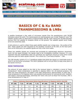
  • 1. BASICS OF C & Ku BAND TRANSMISSIONS & LNBs A satellite broadcasts a few watts of microwave signals from the geostationary orbit 36,000 kilometers above the earth. The transmissions are also broadcast over a wide “footprint” area. The satellite signals suffer an attenuation of approximately 200 dB, while making this 36,000 kilometer journey from the satellite to reception points on the ground. The satellite signals which finally arrive are extremely weak. A dish antenna is used to collect these weak satellite signals over a large area - the surface of the dish. These signals are then focussed by the parabolic curvature of the dish, to the focal point. Even at the focal point, the satellite signals are only a few micro-watts. These tiny satellite signals are received and processed by sophisticated electronic equipment. Given the low signal strength, the signals need to be immediately amplified. However, it is very important that the amplification does not contribute any significant amount of noise which would otherwise spoil the weak signals received. This is done by a “Low Noise Amplifier” - LNA. The LNA actually consist of 2 or 3 amplifying stages that boost the signal to a reasonable level at which it can be further processed. The LNA is designed with an all out effort to keep noise down to the barest minimum. NOISE TEMPERATURE The amount of noise added by the LNA to the received signal is indicated in terms of “Noise Temperature”. Noise temperature is specified in degrees Kelvin. For all practical purposes, the lower the noise temperature, the better is the LNA’s performance. Approximately 10 years ago, a noise temperature of 24 degrees Kelvin was excellent performance for commercial units. However, with today’s improved technology, extremely low noise units such as those from Eurostar, offer a noise temperature of 17 deg. K. Table 1 Indicates Equivalent Noise Specifications In Degrees Kelvin And dB. NF (dB) T (K) NF (dB) T (K) NF (dB) T (K) NF (dB) T (K) 0.1 7 1.1 84 2.1 180 3.1 302 0.2 14 1.2 92 2.2 191 3.2 316 0.3 21 1.3 101 2.3 202 3.3 330 0.4 28 1.4 110 2.4 214 3.4 344 Page 1 of 6Satellite & Cable TV
  • 2. The noise performance depends on the type of amplifying device used for the LNA stages. While C Band LNBs use bipolar transistors, KU band LNBs use GaAsFET transistors for the initial amplification. While it is customary to list the noise temperature for C Band LNBs, KU Band LNBs usually specify their noise, not as a Noise Temperature, but as a Noise Figure, in dB. The dB specification helps compute the total system noise, easily, but the more widespread use of a Noise Figure in db, particularly for Ku Band LNBs probably helps in “specmanship” for marketing purposes. KU band LNBs have much higher noise temperatures, which would not look good on paper. Hence they are quoted in units that look deceptively low, viz dB. C AND KU BANDS The atmosphere provides a low loss signal path for certain microwave frequencies. Satellite broadcasters therefore use this fact and provide satellite broadcasts at these frequencies. The earliest broadcast were at relatively low microwave frequencies. Infact, India’s first rural education satellite broadcast from the SITE satellite in 1975 were at UHF frequencies. India’s first INSAT satellites offered Doordarshan TV broadcasts in the S Band at 2575 MHz & 2615 MHz. Even the INSAT 3C satellite launched on 24th Jan 2002 has 2 S-Band transponders. Most subsequent broadcasts have been in the C Band and Extended C Band range of frequencies. Infact India is the only country that has currently been licensed extended C Band frequencies for commercial use. The amount of signal that a dish receives is directly linked to the frequency. For the same size of dish, the signals received will be larger for higher frequencies that lower frequencies. Technically, this implies that the same dish has a larger “Gain” at higher frequencies. Similarly, a smaller dish could be used at higher frequencies and yet provide the same signal gain. Recognising this, international broadcasters now utilise Ku and even Ka band frequencies for commercial television broadcast via satellite. UPLINKING AND DOWNLINKING A satellite receives television broadcast from a ground station. This is termed as “Uplinking” because the signals are sent up from the ground to the satellite. These signals are then broadcast down over the footprint area in a process called “Downlinking”. Uplinking and Downlinking are shown graphically in Figure 1. To ensure that the uplink and downlink signals do not interfere with each other, separate frequencies are used for uplinking and downlinking. Table 2 indicates the S, C and KU Bands for both uplinking and downlinking. Table to convert Noise Figure (NF) in dB to Noise Temperature in deg. K 0.5 35 1.5 120 2.5 226 3.5 359 0.6 43 1.6 129 2.6 238 3.6 374 0.7 51 1.7 139 2.7 250 3.7 390 0.8 59 1.8 149 2.8 263 3.8 406 0.9 67 1.9 159 2.9 275 3.9 422 1.0 75 2.0 170 3.0 289 4.0 438 Page 2 of 6Satellite & Cable TV
  • 3. THE LNB After the C or KU band frequencies are amplified by the LNA, they need to be processed. The processing is done in the satellite receiver which is usually located 10 meters to 50 meters away from the dish antenna. Microwave signals in the S, C or KU Band would suffer very high attenuation if they were carried via coaxial cable from the LNA to the Satellite Receiver 50 meters away. To overcome this problem, the microwave signals are converted to a block of frequencies from 950 MHz to 2150 MHz. Hence, incoming signals received by the LNA at 2 GHz, 4 GHz and even 12 GHz are even block converted down to 950 MHz to 2150 MHz. This range of frequencies is referred to as Intermediate Frequencies since their range of temporary or intermediate frequencies in the chain of satellite reception which receives microwave signals and finally yields video and audio signals from the satellite receiver. This function is carried out by a “Block Converter” located within the LNB. A combination of Low Noise amplifier + Block converter is referred to as an LNB. A block diagram of a commercial LNB is shown in Figure 2. The Block Converter consists of 4 important sections as shown in Figure 2. MIXER The Block Converter uses the Hetrodyne principle for conversion of a block of S, C or KU Band frequencies to the IF or Intermediate Frequencies. The Hetrodyne principle mixes an external fixed frequency with the incoming frequency. The output from the mixer is a series of signals at the sum and difference of the two inputs to the mixer. Outputs are also produced at multiples of these frequencies. A simple filter is used to suppress all frequency components except those required. LOCAL OSCILLATOR The Local Oscillator (LO) is a section of the LNB and gets its name since it is present locally or within the LNB. The local oscillator produces a fixed output at a pre-determined frequency. The Local Oscillator (LO) frequencies have been standardised by LNB manufacturers worldwide for S, C, Ku and even Ka band frequencies. The LO frequencies have been selected to yield an output in the IF (950 MHz to 2150 MHz) range, for all types of LNBs. As a result, universal satellite receivers can be designed for reception of C and KU Band signals through the same satellite receiver. Table 2 : An Overview Of S, C, Ku & Ka Band Frequencies DOWNLINK FREQ (GHz) UP-LINK FREQ (GHz) S BAND 2.555 to 2.635 5.855 to 5.935 Extended C Band (Lower) 3.4 to 3.7 5.725 to 5.925 C Band 3.7 to 4.2 5.925 to 6.425 Extended C Band (Upper) 4.5 to 4.8 6.425 to 7.075 Ku Band 10.7 to 13.25 12.75 to 14.25 Ka Band 18.3 to 22.20 27.0 to 31.00 Table 3 - Local Oscillator Frequencies Page 3 of 6Satellite & Cable TV
  • 4. Table 3 lists the Local Oscillator frequencies for various LNBs. Do note that since S and Extended C Band LNBs are not used universally, the local oscillator frequency indicated is typical but not an international standard. The output frequency is directly related to the local oscillator frequency. Hence it is very important to have an extremely stable (fixed) local oscillator frequency. To ensure this, most LNBs utilise a crystal oscillator for the LO. This ensures that the LO frequency does not change either with the Input voltage to the LNB or due to temperature changes that the LNB is exposed to. Keep in mind that the LNB is mounted outdoors and is often subjected to sub-zero temperatures with high wind velocities or high ambient temperatures when directly exposed to sunlight in tropical climates such as India. SAMPLE CALCULATION To further illustrate the relevance of a Local Oscillator frequency, let us consider the case of typical C Band reception. The C Band LNB is designed to receive satellite broadcast from 3,800 MHz to 4,200 MHz. The LO within the LNB is standardised at 5150 MHz. Hence when receiving a broadcast at 3,800 MHz, the output frequency of interest is 5150 - 3800 = 1350 MHz Similarly, when receiving a broadcast at 4,200 MHz, the output frequency of interest is 5150 - 4200 = 950 MHz We see that both these output signals viz. at 1350 MHz and 950 MHz lie in the standard IF frequency band that satellite receivers accept. For extended C Band reception, the LO frequency is increased to 5950 MHz so that the output continues to fall within the IF range. In the case of KU Band LNBs, the local oscillator frequency is actually less than the KU band signal. However the LO frequency is chosen so that the difference always lies in the IF frequency range for satellite receivers. FILTER As shown in the LNB Block diagram Figure 2, Bandpass Filters are introduced both before and after the mixer. The filters after the mixer suppress or filter out all frequencies except the required frequency which is the difference between the microwave broadcast and the local oscillator frequency. Reception Freq. L.O. Freq. Output Freq. 2.5 to 2.7 3.65 950 to 1150 3.4 to 4.2 5.15 950 to 1750 4.5 to 4.8 5.95 950 to 1250 10.7 to 11.8 9.75 950 to 2050 10.95 to 11.70 10.0 950 to 1700 11.7 to 12.5 10.6 / 10.75 950 to 1750 12.25 to 12.75 10.6 / 10.75 950 to 1450 12.25 to 12.75 11.3 950 to 1450 12.5 to 12.75 11.475 1025 to 1275 Page 4 of 6Satellite & Cable TV
  • 5. THE KU BAND The KU Band actually used for downlinking spans a wide range of frequencies viz. 10.7 GHz to 12.75 GHz. 1 GHz = 1,000 MHz. This wide range of KU Band frequencies cannot be handled by a single local oscillator frequency. Initial KU Band reception was at 10.7 GHz to 11.8 GHz. The LNBs then utilised a LO of 9.75 GHz. Table 3 indicates various KU Band segments and local oscillator frequencies used to receive these signals. IF AMPLIFIERS The output of the mixer is an IF signal, at a fairly low level. Since this signal is of a specific bandwidth only, it can be easily amplified, significantly. An LNB often includes atleast 2 stages of IF amplification. This amplified signal is then filtered and fed to the output via a DC blocking capacitor. The capacitor allows the signal to pass through but steers the power coming from the satellite receiver, to the LNB power supply. UNIVERSAL LNB KU Band LNBs today effectively split the KU band into 2 frequency segments and utilise separate local oscillators for each of these frequency segments. As an example, the COLORADO Universal LNB receives satellite transmissions from 10.7 GHz to 12.75 GHz. For the lower frequency band, the local oscillator operates at 9.75 GHz. For the upper frequency band, the local oscillator operates at 10.6 GHz, or sometimes 10.75 GHz. The necessary Local Oscillator is activated by send the LNB a burst of 22 KHz signals, from the satellite receiver. When the Satellite receiver is told by the user to tune into a Satellite Channel between 11.7 GHz to 12.75 GHz, the 10.6 GHz local oscillator is activated with a burst of 22 KHz signals. The absence of the tone burst, activates the 9.75 GHz local oscillator. POWER SUPPLY The LNB is remotely powered from the satellite receiver. The same coaxial cable that carries the IF signal from the LNB to the receiver carries power from the receiver to the LNB. As indicated in the LNB Block Diagram (Figure 2), a DC regulator is built in. A DC regulator provides a fixed voltage to all sections of the LNB, irrespective of the input voltage. The Universal LNB operates for DC voltages fed to it in the range of 12.5 Volts upto 24 Volts DC. The current generation of Universal (Ku Band) LNBs are designed to switch their operating characteristics, based on the input Power Supply Voltage it receives, from the Digital Satellite receiver, through the IF Cable. If the Power Supply voltage is between 12.5 V DC to less than 15 volts, the LNB will respond to Table 4 : Universal LNB Polarisation & Power Supply Voltages Power Supply Voltage Received Polarisation 12.5 VDC to 14.5 V DC Vertical Pol. 15 V DC to 24 V DC Horizontal Pol. Page 5 of 6Satellite & Cable TV
  • 6. and receive only Vertically Polarised transmissions. If the Power supply Voltage ranges from more than 15 volts to 24 V DC, the Universal LNB will respond to & receive only horizontally polarised transmissions. The digital satellite receiver usually takes care of this automatically. When the receiver sends a command to tune in to a Vertically Polarised signal, it drops the power supply voltage to between 12.5 V DC to 15 V DC. When the receiver needs to receive Horizontally Polarised signal, it raises the power supply voltage to between 15 V DC to 24 V DC. OVERALL LNB GAIN Most LNBs publish an impressive gain figure of approximately 65 dB. While several advertisements trumpet this figure, a 65 dB gain is fairly standard and is required of all LNBs to amplify the microwave signals to levels required by the satellite receiver. The buyer need not pay undue attention to this parameter. A far more important specification is the Noise temperature, which indicates how much Noise is added to the signal, by the LNB ! It is hoped that this article will provide readers a basic understanding of S, C & Ku band LNBs, including the relevance & importance of noise & the various IF & Local Oscillator frequencies. ■ Contact Details: 27 Madhu Industrial Estate, 1st floor, P. B. Marg, Worli, Bombay - 400 013 India Tel.: 2494 8280, 2498 4273 Fax 91-22-2496 3465 Email: scat@vsnl.com Advertise Page 6 of 6Satellite & Cable TV