Download to read offline


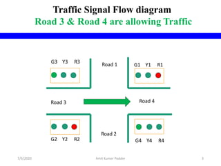
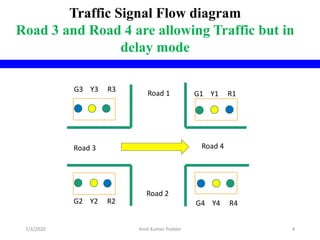
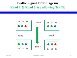
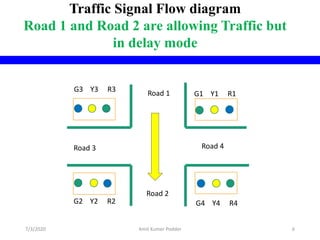
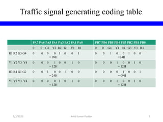
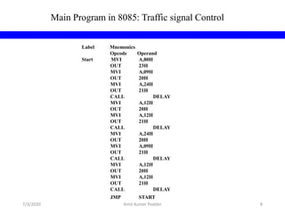
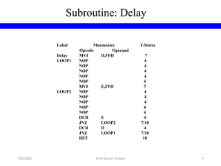
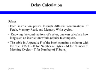
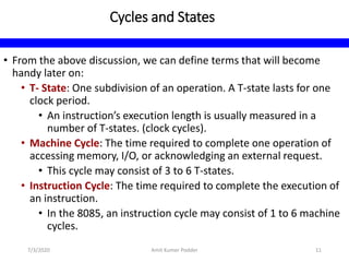
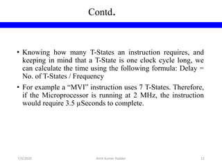
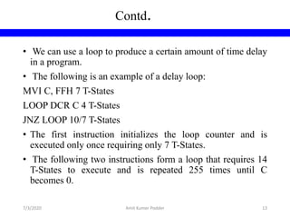
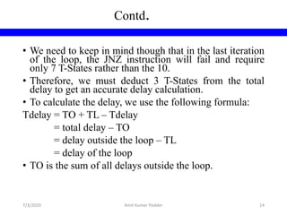
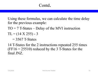


This document describes the design and implementation of a traffic light controller using an 8255 PPI (Programmable Peripheral Interface) chip in an 8085 microprocessor environment. It includes circuit diagrams for the traffic light signals, coding for the traffic light sequences, and an assembly language program that uses delays in a loop to control the light sequences. Memory-mapped I/O is used to control the 8255 PPI pins that output to the traffic lights. Formulas are provided to calculate delay times based on the number of T-states (clock cycles) needed by each instruction.