Download to read offline


![REFERENCES
[1]. Poonam J. Chavan, Manoj Mechkul “IoT Based Water quality Monitoring”, IJMTER
Journal, Vol 3, 2016, pp.746-750. [2]. Aaina Venkateshwaran, Harsha Menda P. prof. Priti Bodar
“An IoT based system for water quality monitoring” ,IJRCCE, 2017, pp. 2510-2515. [3]. Mithali
Borbade, Shruthi Danve “Real Time Water Quality monitoring system” IJIRCE journal, Vol 3,
2015, water pp.5046- 5068. [4]. Anuradha T, Bhakti, Chitra R, pooja D. “IOT based low cost
system for monitoring of water quality in real time”, International Research Journal of
Engineering and Technology, Vol 05, Issue 05, pp. 1658-1663. [5]. Anuradha T. “The
monitoring of water quality in IoT Environment”, IJSRT, March 2018, Volume 4, Issue 5, pp.
[6]. Jyoti Bhatt, Jignesh Pataliya “IoT based water quality monitoring system”, IJIEE journal,
Vol 4, 2016, pp. 44-48. [7]. S.Geeta, S.Goutham “Internet of Things enabled real time water
quality monitoring system” springer open journal Vol 5, pp. 1-19, 2017. [8]. Pradeep Kumar M.
Manisha J. Praveen Sha R. Proiserin V. Suganya Devi, “The real time monitoring of water
quality in IoT Environment”, Vol 5, 2016, pp.4419-4427.](https://image.slidesharecdn.com/automaticwaterdispenser-arduino-201013054411/85/Automatic-water-dispenser-arduino-66-320.jpg)

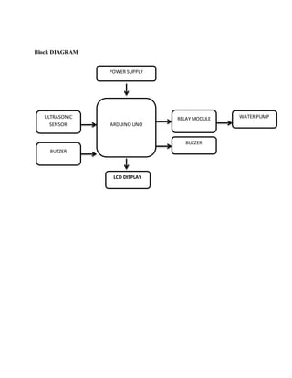
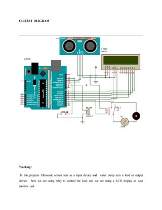
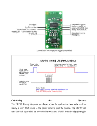
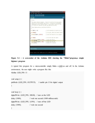
A proposed automatic water dispenser system aims to reduce water wastage through the use of ultrasonic sensors and Arduino technology, eliminating the need for manual taps. The system improves management of water dispensers in public places by maintaining water levels and detecting leaks while offering a cost-effective and user-friendly solution. As water scarcity increases, this innovation addresses significant challenges posed by population growth, pollution, and climate change.