Download as PDF, PPTX


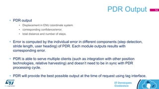
![PDR Mathematical Process
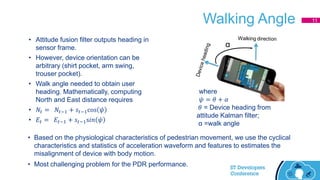
• Velocity and heading are assumed to be constant during the interval when a
step is taken.
• Navigation equation rewritten as a difference equation with piece-wise linear
approximation.
1],1[1
1],1[1
cosˆ
sinˆ
ttttt
ttttt
sNN
sEE
[Nt, Et] = Current position at time t
[Nt-1, Et-1] = Last position at time t-1
𝑠[t-1, t] = Stride length
ψt-1 = User heading
6](https://image.slidesharecdn.com/track4-session3-stdevcon2016-pedestriandeadreckoning-161007094925/85/Track-4-session-3-st-dev-con-2016-pedestrian-dead-reckoning-5-320.jpg)
![Run-time Gyro Bias Calibration
• Driven by accelerometer and gyroscope data.
• Gyro bias is estimated with device stationary condition.
• Fast calibration process. Requires very small amount of data (less than 60
samples) at 50 Hz rate.
[deg.]
-1
0
1
2
3
4
5
6
0.24
0.49
0.74
0.99
1.24
1.49
1.74
1.99
2.24
2.49
2.74
2.99
3.24
3.49
3.74
3.99
4.24
4.49
4.74
4.99
5.24
5.49
5.74
5.99
6.24
6.49
6.74
6.99
7.24
7.49
7.74
7.99
8.24
8.49
8.74
8.99
9.24
9.49
9.74
9.99
10.24
10.49
10.74
10.99
11.24
11.49
11.74
11.99
12.24
12.49
12.74
12.99
13.24
13.49
Gbias estimation library output
Gyro Gbias
[sec.]
10](https://image.slidesharecdn.com/track4-session3-stdevcon2016-pedestriandeadreckoning-161007094925/85/Track-4-session-3-st-dev-con-2016-pedestrian-dead-reckoning-9-320.jpg)
![Configurability of PDR
• Input data: Raw / or calibrated data with minimum sample rate of [50, 50, 25,10] Hz
for Accelerometer, gyroscope, magnetometer, pressure sensor.
• Selection of Raw or Calibrated at time of initialization.
• Modularity: Most of algorithm modules are independent and can run with required
inputs (in terms of sensor data and other inputs such as user Heading need attitude
filter data).
• PDR library can be used to run only a specific algorithm, such as step detection, sensor
calibration, attitude filter. Library can be configured to turn modules ON / off during runtime.
• Scheduling: Each module is responsible for its own scheduling and running
condition.
• Individual module can be disabled /enabled at run time. An algorithm / module execution is not
blocked by other modules. Independent of sensor data acquisition and platform.
13](https://image.slidesharecdn.com/track4-session3-stdevcon2016-pedestriandeadreckoning-161007094925/85/Track-4-session-3-st-dev-con-2016-pedestrian-dead-reckoning-12-320.jpg)

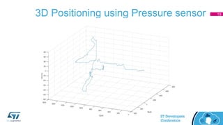
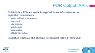
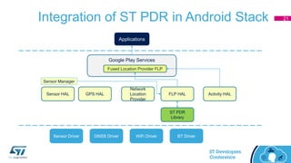


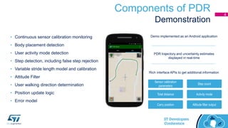
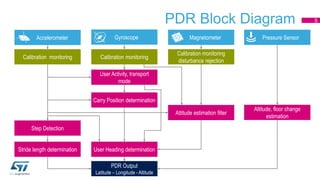
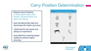
The document provides an overview of ST Microelectronics' Pedestrian Dead Reckoning (PDR) solution for indoor positioning. The PDR system uses MEMS sensors and algorithms to continuously track a user's position without needing connectivity. It consists of components for sensor calibration, step detection, stride length modeling, attitude filtering, carry position determination, and more. The PDR solution provides APIs to output location, activity mode, and other data to applications and can integrate with Android's location services.


![Sensor Fusion Study - Real World 2: GPS & INS Fusion [Stella Seoyeon Yang]](https://cdn.slidesharecdn.com/ss_thumbnails/gpsins-200817095309-thumbnail.jpg?width=640&height=640&fit=bounds)


