SlideShare a Scribd company logo
M9               Shafts: Torsion of Circular Shafts

                            Reading: Crandall, Dahl and Lardner 6.2, 6.3

A shaft is a structural member which is long and slender and subject to a torque
(moment) acting about its long axis. We will only consider circular cross-section shafts
in Unified. These have direct relevance to circular cross-section shafts such as drive
shafts for gas turbine engines, propeller driven aircraft and helicopters (rotorcraft).
However, the basic principles are more general and will provide you with a basis for
understanding how structures with arbitrary cross-sections carry torsional moments.
Torsional stiffness, and the shear stresses that arise from torsional loading are important
for the design of aerodynamic surfaces such as wings, helicopter rotor blades and turbine
fan blades.
Modelling assumptions
      (a)     Geometry (as for beam). Long slender, L >> r (b,h)


      Note: For the time being we will work in tensor notation since this is all about shear
      stresses and tensor notation will make the analysis more straightforward. Remember
      we can choose the system of notation, coordinates to make life easy for ourselves!
(b)    Loading
       Torque about x1 axis, T (units of Force x length). We may also want to consider
the possibility of distributed torques (Force x length/unit length) (distributed aerodynamic
moment along a wing, torques due to individual stages of a gas turbine)


No axial loads (forces) applied to boundaries (on curved surfaces with radial normal, or
on x1 face)


 11 =       22 =   33 = 0
(c)	      Deformation
       -Cross sections rotate as rigid bodies through twist angle , varies with x1 (cf. beams
          – plane sections remain plane and perpendicular)
                          - No bending or extensional deformations in x1 direction

Cross-section:


Torque, T                                                                           Positive x2, x3
right hand                                                                          quadrant
rule
positive


           u2 = r (x1 )sin
           u3 = +r (x1 ) cos


                      2     2
           where r = x2 + x 3


                x                x
           sin = 3          cos = 2
                 r                r
2     2                x3
     so u2 =          x2 + x 3      (x1 )               =   (x1 )x 3
                                              2     2
                                             x2 + x 3

                  2     2               x2
     u3 =        x2 + x 3   (x1 )                  = (x1 )x2
                                       2     2
                                      x2 + x 3

So
                            u1 = 0                                     (1)
                            u2 =        (x1 )x 3                         (2)
                            u3 = (x1 )x2                               ( 3)

Governing Equations
              du1
     11   =        = 0

              dx1

              du2
     22   =       =0                  Consistent with assumption of no axial,
              dx2                     or radial stresses, strains
              du 3
     33   =        =0
              dx 3

              1 ∂u1 ∂u 2            1    d
     12 =          +     =            x3                                       (4 )
              2 ∂x2 ∂x1             2 dx1

              1 ∂u1 ∂u3  1   d
     13 =          +    = x2                                                   (5)
              2 ∂x3 ∂x1  2   dx1

              1 ∂u 2 ∂u3  1
     23 =           +    = (           (x1 ) + (x1 )) = 0
              2 ∂x3 ∂x2   2
Next, apply constitutive laws, i.e. stress-strain relations (assume isotropic),

remember we are working in tensor notation: mn =            mn , therefore need “2G”
                                                           2G

                           23   = 23 = 0
                                 2G

                             12   = 12                           (6)
                                   2G

                             13   = 13                           (7)
                                    2G

Net moment due to shear stresses must equal resultant torque on section:

equipollent torque, T =           ( x2   13   x 3 12 )dx2 dx 3                            (8)


                         ∂ mn
   Apply equilibrium:          + fn = 0
                          ∂x m
                ∂ 11 ∂ 21 ∂ 31
   i.e.:             +      +      =0
                 ∂x1   ∂x 2   ∂x 3
                ∂ 12 ∂ 22 ∂ 32
                     +      +      =0
                 ∂x1   ∂x 2   ∂x 3
                ∂ 13 ∂ 23 ∂ 33
                     +      +      =0
                 ∂x1   ∂x 2   ∂x 3
Retaining non-zero terms we obtain

       ∂ 21 ∂ 31
             +       =0                          (9) 

        ∂x 2   ∂x 3

       ∂ 12
             =0                                  (10) 

        ∂x1

       ∂ 13
             =0                                  (11) 

        ∂x1

Solution
   Go back to stress-displacement relationships (4,5, 6 and 7)


                               1    d
           12 = 2G 12 = 2G       x3
                               2 dx1
                              d
                    12 = Gx 3
                              dx1

Similarly:
                                     1    d         d
             13 = 2G13 13 = 2G         x2     = Gx2
                                     2    dx1       dx1

Substitute into equation for resultant moment (8)

           T=     (x 2    13   x 3 12 )dx2 dx3

                   2      d     2 d
             =    x2         + x3     dx 2dx3
                         dx1      dx1
           T =G
                  d
                  dx1

                           ( x2 + x2 )dA
                              2    3


define J =       x2
 + x 2 dA
                  2      3


                   Polar 2nd moment of area

       R4
   =      for circular cross-section
       2
d
   Hence T = GJ
                   dx1


                              Torque-twist relation


                                 d                         ∂2 w
(note, we can compare T = GJ        for shafts with M = EI      for beams)
                                dx1                        ∂x 2

Hence, relate stress to torque
                  Tx3
          12 =
                    J

                Tx2

          13 =
                  J
Express total shear as shear stress resultant,


                     2    2    T           2    2     Tr
           res =     12 + 13 =           x 3 + x2 =
                                   J                   J
                         Tr                   Mz
        compare      =      with       xx =
                          J                    I

   Model works well for circular cross-sections and cylindrical tubes    J = J1 J2
Does not work for open sections:


   We can approximate for other sections, e.g. square cross-section, J = 0.141a4 .


For a full treatment of torsion of slender members see 16.20.
A note on distributed torques:

Distributed torques are similar to distributed loads on beams: Consider equilibrium of a
differential element, length dx1, with a distributed torque t (Nm/m) applied. Leads to an
increase in the resultant internal torque, T from T to T+dT.


                                                                       dT
                                                                  T+      dx
                                                                       dx1 1


                                              dT
  M x1 = 0            T + t(x1 )dx1 + T +        dx
                                              dx1 1


             dT                        dS
                 = t(x 1)       c.f.      = q( x)
             dx1                       dx


        Can also consider macroscopic equilibrium of shaft fixed at one end with a
        uniform distributed torque/length, t, applied to it:


                                                            t/unit length


             FBD


                            L
                      TA + tdx1 = 0
                            0
                                   TA = tL
M10 Introduction to Structural Instability

               Reading Crandall, Dahl and Lardner: 9.2, 9.3
Elastic instabilities, of which buckling is the most important example, are a key limitation
on structural integrity. The key feature of an elastic instability is the transition from a
stable mode of deformation with increasing applied load to an unstable one, resulting in
collapse (loss of load carrying capability) and possibly failure of the structure. Examples
of elastic collapse are the buckling of bars in a truss under compressive load, the failure
of columns under compressive load, the failure of the webs of “I” beams in shear, the
failure of fuselage and wing skin panels in shear and many others. The only particular
case we will consider here in Unified is the failure of a bar or column loaded in axial
compression, however, as for the other slender members we have considered, the basic
ideas will apply to more complex structures.
A structure is in stable equilibrium if, for all possible (small)displacements/deformations,
a restoring force arises.
Before considering the case of a continuous structure we will consider a case in which we
separate the stiffness of the structure from the geometry of the structure.

Introductory Example:

Rigid, massless bar with a torsional spring at one end, stiffness, kt, which is also pinned. .
The bar is loaded by a pair of horizontal and vertical forces at the free end, P1, P2. The
bar undergoes a small angular displacement, .


                                                     Independent applied
                                                     loads, P1, P2


                                               is small – exaggerated in the figure
Draw free body diagram:


              Horizontal equilibrium: HA=-P1

              Vertical equilibrium:         VA=P2

Taking moments, counterclockwise positive:

         M     LP cos
                 1           P2 L sin = 0
                  (cos      1 sin            )
         M     LP P2 L = 0
                 1


And              =k
           k t M LP1t L P2 = 0
                 K P2 L
Hence:     P1 = t
                     L


         Effective Stiffness - (note that
         it includes the load, P2)
i.e.

P = keff
 1
                                     P1
Rearranging gives:          =
                                kt
                                          P2
                                L
Hence:
                   for P1       0
                    = 0 for P2 < k t / L
                    = • for P2 K t / L
               Kt
i.e. if P2 ≥           static instability, i.e., spring cannot provide in restoring moment
               L
NOTE:	        If P2 negative - i.e. upward -stiffness increases
              But if P1and P2 removed or reduced, spring will allow bar to spring back to
              original configuration

Plot Load vs. Displacement
a) for case when P1=0. Obtain “bifurcation behavior”


       Bifurcation point
              Kt
       P2 =
              L
b) case P1>0


Next time we will apply these idea to a column, i.e. a continuous structure with a
continuous distribution of stiffness. Need to think about what is the relevant structural
stiffness, i.e. the equivalent of (K t L ) in the spring/rigid rod system above.

More Related Content

What's hot

Solution manual 7 8
Solution manual 7 8Solution manual 7 8
Solution manual 7 8
Rafi Flydarkzz
 
Gold1
Gold1Gold1
Gold1
egsamit
 
Lecture 12 deflection in beams
Lecture 12 deflection in beamsLecture 12 deflection in beams
Lecture 12 deflection in beamsDeepak Agarwal
 
Newton's Laws of Motion L2.1
Newton's Laws of Motion L2.1Newton's Laws of Motion L2.1
Newton's Laws of Motion L2.1
Claudia Kopanovski
 
Solucionario Mecácnica Clásica Goldstein
Solucionario Mecácnica Clásica GoldsteinSolucionario Mecácnica Clásica Goldstein
Solucionario Mecácnica Clásica Goldstein
Fredy Mojica
 
elastic constants
elastic constantselastic constants
elastic constants
Karan Patel
 
Energy principle in structure analysis in civil engineering
Energy principle in structure analysis in civil engineeringEnergy principle in structure analysis in civil engineering
Energy principle in structure analysis in civil engineering
Nagma Modi
 
Formul me-3074683 Erdi Karaçal Mechanical Engineer University of Gaziantep
Formul me-3074683 Erdi Karaçal Mechanical Engineer University of GaziantepFormul me-3074683 Erdi Karaçal Mechanical Engineer University of Gaziantep
Formul me-3074683 Erdi Karaçal Mechanical Engineer University of Gaziantep
Erdi Karaçal
 
Me307 machine elements formula sheet Erdi Karaçal Mechanical Engineer Univers...
Me307 machine elements formula sheet Erdi Karaçal Mechanical Engineer Univers...Me307 machine elements formula sheet Erdi Karaçal Mechanical Engineer Univers...
Me307 machine elements formula sheet Erdi Karaçal Mechanical Engineer Univers...
Erdi Karaçal
 
Dynamics of structures 5th edition chopra solutions manual
Dynamics of structures 5th edition chopra solutions manualDynamics of structures 5th edition chopra solutions manual
Dynamics of structures 5th edition chopra solutions manual
Schneiderxds
 
Study of Strain Energy due to Shear, Bending and Torsion
Study of Strain Energy due to Shear, Bending and TorsionStudy of Strain Energy due to Shear, Bending and Torsion
Study of Strain Energy due to Shear, Bending and Torsion
Jay1997Singhania
 
Torsion of circular shafts
Torsion of circular shaftsTorsion of circular shafts
Torsion of circular shafts
Yatin Singh
 
SFD & BMD
SFD & BMDSFD & BMD
Lec5 total potential_energy_method
Lec5 total potential_energy_methodLec5 total potential_energy_method
Lec5 total potential_energy_method
Mahdi Damghani
 
Castigliano’s Method
Castigliano’s MethodCastigliano’s Method
Castigliano’s Method
aapx
 
FUNDAMENTALS OF PHYSICS
FUNDAMENTALS OF PHYSICSFUNDAMENTALS OF PHYSICS
FUNDAMENTALS OF PHYSICS
Rijo Tom
 

What's hot (18)

Solution manual 7 8
Solution manual 7 8Solution manual 7 8
Solution manual 7 8
 
Gold1
Gold1Gold1
Gold1
 
Lecture 12 deflection in beams
Lecture 12 deflection in beamsLecture 12 deflection in beams
Lecture 12 deflection in beams
 
Newton's Laws of Motion L2.1
Newton's Laws of Motion L2.1Newton's Laws of Motion L2.1
Newton's Laws of Motion L2.1
 
Solucionario Mecácnica Clásica Goldstein
Solucionario Mecácnica Clásica GoldsteinSolucionario Mecácnica Clásica Goldstein
Solucionario Mecácnica Clásica Goldstein
 
elastic constants
elastic constantselastic constants
elastic constants
 
Energy principle in structure analysis in civil engineering
Energy principle in structure analysis in civil engineeringEnergy principle in structure analysis in civil engineering
Energy principle in structure analysis in civil engineering
 
Formul me-3074683 Erdi Karaçal Mechanical Engineer University of Gaziantep
Formul me-3074683 Erdi Karaçal Mechanical Engineer University of GaziantepFormul me-3074683 Erdi Karaçal Mechanical Engineer University of Gaziantep
Formul me-3074683 Erdi Karaçal Mechanical Engineer University of Gaziantep
 
Me307 machine elements formula sheet Erdi Karaçal Mechanical Engineer Univers...
Me307 machine elements formula sheet Erdi Karaçal Mechanical Engineer Univers...Me307 machine elements formula sheet Erdi Karaçal Mechanical Engineer Univers...
Me307 machine elements formula sheet Erdi Karaçal Mechanical Engineer Univers...
 
Dynamics of structures 5th edition chopra solutions manual
Dynamics of structures 5th edition chopra solutions manualDynamics of structures 5th edition chopra solutions manual
Dynamics of structures 5th edition chopra solutions manual
 
Study of Strain Energy due to Shear, Bending and Torsion
Study of Strain Energy due to Shear, Bending and TorsionStudy of Strain Energy due to Shear, Bending and Torsion
Study of Strain Energy due to Shear, Bending and Torsion
 
wave_equation
wave_equationwave_equation
wave_equation
 
Torsion of circular shafts
Torsion of circular shaftsTorsion of circular shafts
Torsion of circular shafts
 
SFD & BMD
SFD & BMDSFD & BMD
SFD & BMD
 
Lec5 total potential_energy_method
Lec5 total potential_energy_methodLec5 total potential_energy_method
Lec5 total potential_energy_method
 
Shear
ShearShear
Shear
 
Castigliano’s Method
Castigliano’s MethodCastigliano’s Method
Castigliano’s Method
 
FUNDAMENTALS OF PHYSICS
FUNDAMENTALS OF PHYSICSFUNDAMENTALS OF PHYSICS
FUNDAMENTALS OF PHYSICS
 

Viewers also liked

H.crandell chapter4 solution
H.crandell chapter4 solutionH.crandell chapter4 solution
H.crandell chapter4 solution
Deepak Kumar
 
solution of crandall chapter 9
solution of crandall chapter 9solution of crandall chapter 9
solution of crandall chapter 9MURARI KUMAR
 
Unit 8: Torsion of circular shafts and elastic stability of columns
Unit 8: Torsion of circular shafts and elastic stability of columnsUnit 8: Torsion of circular shafts and elastic stability of columns
Unit 8: Torsion of circular shafts and elastic stability of columns
Hareesha N Gowda, Dayananda Sagar College of Engg, Bangalore
 
Torsion of thin closed sections
Torsion of thin closed sectionsTorsion of thin closed sections
Torsion of thin closed sectionsaero103
 
Torsional Stress
Torsional StressTorsional Stress
Torsional Stresslimon1705
 
Torsion problems& answers part 1
Torsion problems& answers part 1Torsion problems& answers part 1
Torsion problems& answers part 1Mohamed Salah
 
Lesson 07, torsion
Lesson 07, torsionLesson 07, torsion
Lesson 07, torsion
Msheer Bargaray
 
3 torsion- Mechanics of Materials - 4th - Beer
3 torsion- Mechanics of Materials - 4th - Beer3 torsion- Mechanics of Materials - 4th - Beer
3 torsion- Mechanics of Materials - 4th - Beer
Nhan Tran
 
Torsion
TorsionTorsion
Torsion
Arif Samoon
 
TORSION (MECHANICS OF SOLIDS)
TORSION (MECHANICS OF SOLIDS)TORSION (MECHANICS OF SOLIDS)
TORSION (MECHANICS OF SOLIDS)
Er.Navazhushen Patel
 
Lecture 13 torsion in solid and hollow shafts 1
Lecture 13 torsion in solid and hollow shafts 1Lecture 13 torsion in solid and hollow shafts 1
Lecture 13 torsion in solid and hollow shafts 1Deepak Agarwal
 

Viewers also liked (12)

H.crandell chapter4 solution
H.crandell chapter4 solutionH.crandell chapter4 solution
H.crandell chapter4 solution
 
solution of crandall chapter 9
solution of crandall chapter 9solution of crandall chapter 9
solution of crandall chapter 9
 
Unit 8: Torsion of circular shafts and elastic stability of columns
Unit 8: Torsion of circular shafts and elastic stability of columnsUnit 8: Torsion of circular shafts and elastic stability of columns
Unit 8: Torsion of circular shafts and elastic stability of columns
 
Torsion of thin closed sections
Torsion of thin closed sectionsTorsion of thin closed sections
Torsion of thin closed sections
 
Kuliah torsion
Kuliah torsionKuliah torsion
Kuliah torsion
 
Torsional Stress
Torsional StressTorsional Stress
Torsional Stress
 
Torsion problems& answers part 1
Torsion problems& answers part 1Torsion problems& answers part 1
Torsion problems& answers part 1
 
Lesson 07, torsion
Lesson 07, torsionLesson 07, torsion
Lesson 07, torsion
 
3 torsion- Mechanics of Materials - 4th - Beer
3 torsion- Mechanics of Materials - 4th - Beer3 torsion- Mechanics of Materials - 4th - Beer
3 torsion- Mechanics of Materials - 4th - Beer
 
Torsion
TorsionTorsion
Torsion
 
TORSION (MECHANICS OF SOLIDS)
TORSION (MECHANICS OF SOLIDS)TORSION (MECHANICS OF SOLIDS)
TORSION (MECHANICS OF SOLIDS)
 
Lecture 13 torsion in solid and hollow shafts 1
Lecture 13 torsion in solid and hollow shafts 1Lecture 13 torsion in solid and hollow shafts 1
Lecture 13 torsion in solid and hollow shafts 1
 

Similar to Torsion of circular shafts

Engr 213 midterm 2b sol 2010
Engr 213 midterm 2b sol 2010Engr 213 midterm 2b sol 2010
Engr 213 midterm 2b sol 2010akabaka12
 
Lesson 8: Derivatives of Logarithmic and Exponential Functions (worksheet sol...
Lesson 8: Derivatives of Logarithmic and Exponential Functions (worksheet sol...Lesson 8: Derivatives of Logarithmic and Exponential Functions (worksheet sol...
Lesson 8: Derivatives of Logarithmic and Exponential Functions (worksheet sol...Matthew Leingang
 
Bahan ajar kalkulus integral
Bahan ajar kalkulus integralBahan ajar kalkulus integral
Bahan ajar kalkulus integral
grand_livina_good
 
Engr 213 midterm 2a sol 2010
Engr 213 midterm 2a sol 2010Engr 213 midterm 2a sol 2010
Engr 213 midterm 2a sol 2010akabaka12
 
Week 2
Week 2 Week 2
Week 2
Hazrul156
 
Calculus Final Exam
Calculus Final ExamCalculus Final Exam
Calculus Final Exam
Kuan-Lun Wang
 
Answer to selected_miscellaneous_exercises
Answer to selected_miscellaneous_exercisesAnswer to selected_miscellaneous_exercises
Answer to selected_miscellaneous_exercisespaufong
 
Holographic Cotton Tensor
Holographic Cotton TensorHolographic Cotton Tensor
Holographic Cotton Tensor
Sebastian De Haro
 
整卷
整卷整卷
Integration techniques
Integration techniquesIntegration techniques
Integration techniquesKrishna Gali
 
Engr 213 final sol 2009
Engr 213 final sol 2009Engr 213 final sol 2009
Engr 213 final sol 2009akabaka12
 
Eight Regression Algorithms
Eight Regression AlgorithmsEight Regression Algorithms
Eight Regression Algorithmsguestfee8698
 
4.2 derivatives of logarithmic functions
4.2 derivatives of logarithmic functions4.2 derivatives of logarithmic functions
4.2 derivatives of logarithmic functionsdicosmo178
 
Maths assignment
Maths assignmentMaths assignment
Maths assignmentNtshima
 
Beam theory
Beam theoryBeam theory
Beam theory
bissla19
 
Differentiation jan 21, 2014
Differentiation jan 21, 2014Differentiation jan 21, 2014
Differentiation jan 21, 2014
Mohammed Ahmed
 

Similar to Torsion of circular shafts (20)

Engr 213 midterm 2b sol 2010
Engr 213 midterm 2b sol 2010Engr 213 midterm 2b sol 2010
Engr 213 midterm 2b sol 2010
 
Lesson 8: Derivatives of Logarithmic and Exponential Functions (worksheet sol...
Lesson 8: Derivatives of Logarithmic and Exponential Functions (worksheet sol...Lesson 8: Derivatives of Logarithmic and Exponential Functions (worksheet sol...
Lesson 8: Derivatives of Logarithmic and Exponential Functions (worksheet sol...
 
Sect1 2
Sect1 2Sect1 2
Sect1 2
 
Bahan ajar kalkulus integral
Bahan ajar kalkulus integralBahan ajar kalkulus integral
Bahan ajar kalkulus integral
 
Engr 213 midterm 2a sol 2010
Engr 213 midterm 2a sol 2010Engr 213 midterm 2a sol 2010
Engr 213 midterm 2a sol 2010
 
Week 2
Week 2 Week 2
Week 2
 
Calculus Final Exam
Calculus Final ExamCalculus Final Exam
Calculus Final Exam
 
125 5.2
125 5.2125 5.2
125 5.2
 
Answer to selected_miscellaneous_exercises
Answer to selected_miscellaneous_exercisesAnswer to selected_miscellaneous_exercises
Answer to selected_miscellaneous_exercises
 
Holographic Cotton Tensor
Holographic Cotton TensorHolographic Cotton Tensor
Holographic Cotton Tensor
 
整卷
整卷整卷
整卷
 
Sol83
Sol83Sol83
Sol83
 
Sol83
Sol83Sol83
Sol83
 
Integration techniques
Integration techniquesIntegration techniques
Integration techniques
 
Engr 213 final sol 2009
Engr 213 final sol 2009Engr 213 final sol 2009
Engr 213 final sol 2009
 
Eight Regression Algorithms
Eight Regression AlgorithmsEight Regression Algorithms
Eight Regression Algorithms
 
4.2 derivatives of logarithmic functions
4.2 derivatives of logarithmic functions4.2 derivatives of logarithmic functions
4.2 derivatives of logarithmic functions
 
Maths assignment
Maths assignmentMaths assignment
Maths assignment
 
Beam theory
Beam theoryBeam theory
Beam theory
 
Differentiation jan 21, 2014
Differentiation jan 21, 2014Differentiation jan 21, 2014
Differentiation jan 21, 2014
 

More from aero103

Bending1
Bending1Bending1
Bending1aero103
 
Bending and distributed loads
Bending and distributed loadsBending and distributed loads
Bending and distributed loadsaero103
 
roller coasters
roller coastersroller coasters
roller coastersaero103
 
Bending 3
Bending 3Bending 3
Bending 3aero103
 
Bending 2
Bending 2Bending 2
Bending 2aero103
 
Stress deflections shafts in torsion
Stress   deflections shafts in torsionStress   deflections shafts in torsion
Stress deflections shafts in torsionaero103
 
Shearing & torsion of shell beams
Shearing & torsion of shell beamsShearing & torsion of shell beams
Shearing & torsion of shell beamsaero103
 
Shear & torsion
Shear & torsionShear & torsion
Shear & torsionaero103
 
7laha (stress and strain)
7laha (stress and strain)7laha (stress and strain)
7laha (stress and strain)aero103
 
7laha in equilibruim 2
7laha in equilibruim 27laha in equilibruim 2
7laha in equilibruim 2aero103
 
Structure is life 1
Structure  is life 1Structure  is life 1
Structure is life 1aero103
 
7laha in equilibruim
7laha in equilibruim7laha in equilibruim
7laha in equilibruimaero103
 
Stress & strain notes 222
Stress & strain notes 222Stress & strain notes 222
Stress & strain notes 222aero103
 
6 stress on trusses
6 stress on trusses6 stress on trusses
6 stress on trussesaero103
 
6 stress on trusses
6 stress on trusses6 stress on trusses
6 stress on trussesaero103
 
4 mechanics and materials lec2
4 mechanics and materials   lec24 mechanics and materials   lec2
4 mechanics and materials lec2aero103
 
3 mechanics and materials lec1
3 mechanics and materials   lec13 mechanics and materials   lec1
3 mechanics and materials lec1aero103
 
2 equilibrium problem soliving
2 equilibrium problem soliving2 equilibrium problem soliving
2 equilibrium problem solivingaero103
 

More from aero103 (20)

Bending1
Bending1Bending1
Bending1
 
Bending and distributed loads
Bending and distributed loadsBending and distributed loads
Bending and distributed loads
 
roller coasters
roller coastersroller coasters
roller coasters
 
Bending 3
Bending 3Bending 3
Bending 3
 
Bending 2
Bending 2Bending 2
Bending 2
 
Stress deflections shafts in torsion
Stress   deflections shafts in torsionStress   deflections shafts in torsion
Stress deflections shafts in torsion
 
Shearing & torsion of shell beams
Shearing & torsion of shell beamsShearing & torsion of shell beams
Shearing & torsion of shell beams
 
Shear & torsion
Shear & torsionShear & torsion
Shear & torsion
 
8
88
8
 
6
66
6
 
7laha (stress and strain)
7laha (stress and strain)7laha (stress and strain)
7laha (stress and strain)
 
7laha in equilibruim 2
7laha in equilibruim 27laha in equilibruim 2
7laha in equilibruim 2
 
Structure is life 1
Structure  is life 1Structure  is life 1
Structure is life 1
 
7laha in equilibruim
7laha in equilibruim7laha in equilibruim
7laha in equilibruim
 
Stress & strain notes 222
Stress & strain notes 222Stress & strain notes 222
Stress & strain notes 222
 
6 stress on trusses
6 stress on trusses6 stress on trusses
6 stress on trusses
 
6 stress on trusses
6 stress on trusses6 stress on trusses
6 stress on trusses
 
4 mechanics and materials lec2
4 mechanics and materials   lec24 mechanics and materials   lec2
4 mechanics and materials lec2
 
3 mechanics and materials lec1
3 mechanics and materials   lec13 mechanics and materials   lec1
3 mechanics and materials lec1
 
2 equilibrium problem soliving
2 equilibrium problem soliving2 equilibrium problem soliving
2 equilibrium problem soliving
 

Torsion of circular shafts

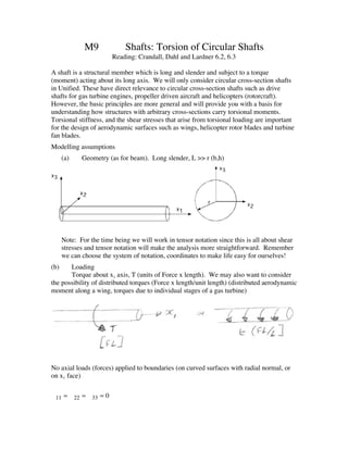
  • 1. M9 Shafts: Torsion of Circular Shafts Reading: Crandall, Dahl and Lardner 6.2, 6.3 A shaft is a structural member which is long and slender and subject to a torque (moment) acting about its long axis. We will only consider circular cross-section shafts in Unified. These have direct relevance to circular cross-section shafts such as drive shafts for gas turbine engines, propeller driven aircraft and helicopters (rotorcraft). However, the basic principles are more general and will provide you with a basis for understanding how structures with arbitrary cross-sections carry torsional moments. Torsional stiffness, and the shear stresses that arise from torsional loading are important for the design of aerodynamic surfaces such as wings, helicopter rotor blades and turbine fan blades. Modelling assumptions (a) Geometry (as for beam). Long slender, L >> r (b,h) Note: For the time being we will work in tensor notation since this is all about shear stresses and tensor notation will make the analysis more straightforward. Remember we can choose the system of notation, coordinates to make life easy for ourselves! (b) Loading Torque about x1 axis, T (units of Force x length). We may also want to consider the possibility of distributed torques (Force x length/unit length) (distributed aerodynamic moment along a wing, torques due to individual stages of a gas turbine) No axial loads (forces) applied to boundaries (on curved surfaces with radial normal, or on x1 face) 11 = 22 = 33 = 0
  • 2. (c) Deformation -Cross sections rotate as rigid bodies through twist angle , varies with x1 (cf. beams – plane sections remain plane and perpendicular) - No bending or extensional deformations in x1 direction Cross-section: Torque, T Positive x2, x3 right hand quadrant rule positive u2 = r (x1 )sin u3 = +r (x1 ) cos 2 2 where r = x2 + x 3 x x sin = 3 cos = 2 r r
  • 3. 2 2 x3 so u2 = x2 + x 3 (x1 ) = (x1 )x 3 2 2 x2 + x 3 2 2 x2 u3 = x2 + x 3 (x1 ) = (x1 )x2 2 2 x2 + x 3 So u1 = 0 (1) u2 = (x1 )x 3 (2) u3 = (x1 )x2 ( 3) Governing Equations du1 11 = = 0 dx1 du2 22 = =0 Consistent with assumption of no axial, dx2 or radial stresses, strains du 3 33 = =0 dx 3 1 ∂u1 ∂u 2 1 d 12 = + = x3 (4 ) 2 ∂x2 ∂x1 2 dx1 1 ∂u1 ∂u3 1 d 13 = + = x2 (5) 2 ∂x3 ∂x1 2 dx1 1 ∂u 2 ∂u3 1 23 = + = ( (x1 ) + (x1 )) = 0 2 ∂x3 ∂x2 2
  • 4. Next, apply constitutive laws, i.e. stress-strain relations (assume isotropic), remember we are working in tensor notation: mn = mn , therefore need “2G” 2G 23 = 23 = 0 2G 12 = 12 (6) 2G 13 = 13 (7) 2G Net moment due to shear stresses must equal resultant torque on section: equipollent torque, T = ( x2 13 x 3 12 )dx2 dx 3 (8) ∂ mn Apply equilibrium: + fn = 0 ∂x m ∂ 11 ∂ 21 ∂ 31 i.e.: + + =0 ∂x1 ∂x 2 ∂x 3 ∂ 12 ∂ 22 ∂ 32 + + =0 ∂x1 ∂x 2 ∂x 3 ∂ 13 ∂ 23 ∂ 33 + + =0 ∂x1 ∂x 2 ∂x 3
  • 5. Retaining non-zero terms we obtain ∂ 21 ∂ 31 + =0 (9) ∂x 2 ∂x 3 ∂ 12 =0 (10) ∂x1 ∂ 13 =0 (11) ∂x1 Solution Go back to stress-displacement relationships (4,5, 6 and 7) 1 d 12 = 2G 12 = 2G x3 2 dx1 d 12 = Gx 3 dx1 Similarly: 1 d d 13 = 2G13 13 = 2G x2 = Gx2 2 dx1 dx1 Substitute into equation for resultant moment (8) T= (x 2 13 x 3 12 )dx2 dx3 2 d 2 d = x2 + x3 dx 2dx3 dx1 dx1 T =G d dx1 ( x2 + x2 )dA 2 3 define J = x2 + x 2 dA 2 3 Polar 2nd moment of area R4 = for circular cross-section 2
  • 6. d Hence T = GJ dx1 Torque-twist relation d ∂2 w (note, we can compare T = GJ for shafts with M = EI for beams) dx1 ∂x 2 Hence, relate stress to torque Tx3 12 = J Tx2 13 = J Express total shear as shear stress resultant, 2 2 T 2 2 Tr res = 12 + 13 = x 3 + x2 = J J Tr Mz compare = with xx = J I Model works well for circular cross-sections and cylindrical tubes J = J1 J2
  • 7. Does not work for open sections: We can approximate for other sections, e.g. square cross-section, J = 0.141a4 . For a full treatment of torsion of slender members see 16.20.
  • 8. A note on distributed torques: Distributed torques are similar to distributed loads on beams: Consider equilibrium of a differential element, length dx1, with a distributed torque t (Nm/m) applied. Leads to an increase in the resultant internal torque, T from T to T+dT. dT T+ dx dx1 1 dT M x1 = 0 T + t(x1 )dx1 + T + dx dx1 1 dT dS = t(x 1) c.f. = q( x) dx1 dx Can also consider macroscopic equilibrium of shaft fixed at one end with a uniform distributed torque/length, t, applied to it: t/unit length FBD L TA + tdx1 = 0 0 TA = tL
  • 9. M10 Introduction to Structural Instability Reading Crandall, Dahl and Lardner: 9.2, 9.3 Elastic instabilities, of which buckling is the most important example, are a key limitation on structural integrity. The key feature of an elastic instability is the transition from a stable mode of deformation with increasing applied load to an unstable one, resulting in collapse (loss of load carrying capability) and possibly failure of the structure. Examples of elastic collapse are the buckling of bars in a truss under compressive load, the failure of columns under compressive load, the failure of the webs of “I” beams in shear, the failure of fuselage and wing skin panels in shear and many others. The only particular case we will consider here in Unified is the failure of a bar or column loaded in axial compression, however, as for the other slender members we have considered, the basic ideas will apply to more complex structures. A structure is in stable equilibrium if, for all possible (small)displacements/deformations, a restoring force arises. Before considering the case of a continuous structure we will consider a case in which we separate the stiffness of the structure from the geometry of the structure. Introductory Example: Rigid, massless bar with a torsional spring at one end, stiffness, kt, which is also pinned. . The bar is loaded by a pair of horizontal and vertical forces at the free end, P1, P2. The bar undergoes a small angular displacement, . Independent applied loads, P1, P2 is small – exaggerated in the figure
  • 10. Draw free body diagram: Horizontal equilibrium: HA=-P1 Vertical equilibrium: VA=P2 Taking moments, counterclockwise positive: M LP cos 1 P2 L sin = 0 (cos 1 sin ) M LP P2 L = 0 1 And =k k t M LP1t L P2 = 0 K P2 L Hence: P1 = t L Effective Stiffness - (note that it includes the load, P2)
  • 11. i.e. P = keff 1 P1 Rearranging gives: = kt P2 L Hence: for P1 0 = 0 for P2 < k t / L = • for P2 K t / L Kt i.e. if P2 ≥ static instability, i.e., spring cannot provide in restoring moment L NOTE: If P2 negative - i.e. upward -stiffness increases But if P1and P2 removed or reduced, spring will allow bar to spring back to original configuration Plot Load vs. Displacement a) for case when P1=0. Obtain “bifurcation behavior” Bifurcation point Kt P2 = L
  • 12. b) case P1>0 Next time we will apply these idea to a column, i.e. a continuous structure with a continuous distribution of stiffness. Need to think about what is the relevant structural stiffness, i.e. the equivalent of (K t L ) in the spring/rigid rod system above.