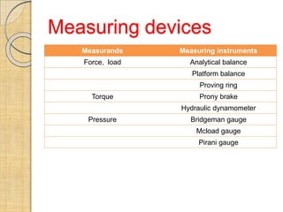
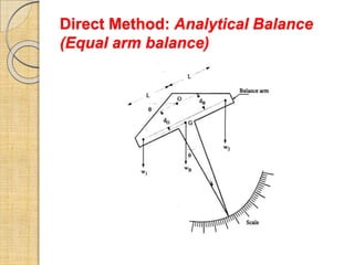
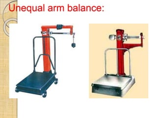
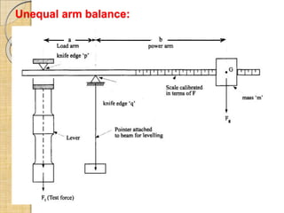
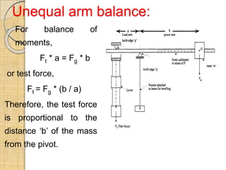
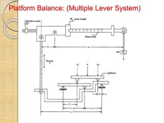
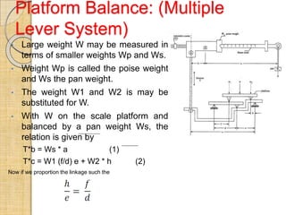
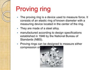
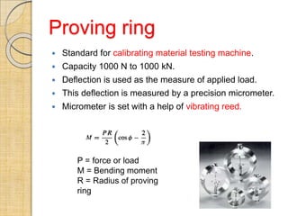
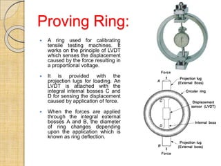
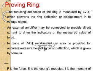
1. Devices used to measure force include analytical balances, platform balances, and proving rings. Proving rings measure force through the deflection of an elastic ring.
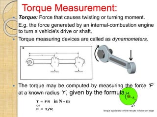
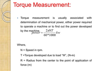
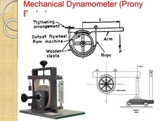
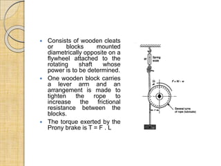
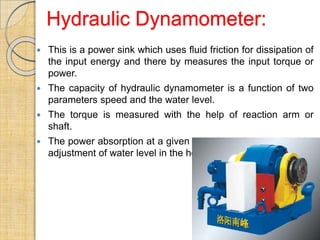
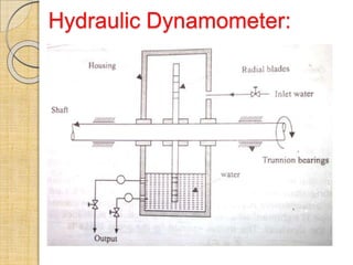
2. Torque can be measured using dynamometers like the Prony brake and hydraulic dynamometer. The Prony brake uses friction between wooden blocks to exert torque, while the hydraulic dynamometer absorbs power through fluid friction.
3. Pressure is measured using instruments like the Bridgeman gauge and McLeod gauge that rely on the behavior of gases under changes in pressure.