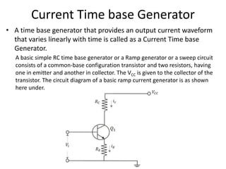
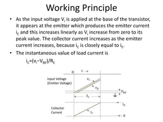
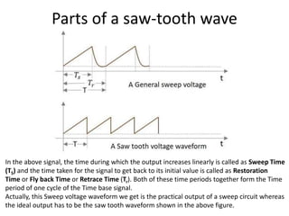
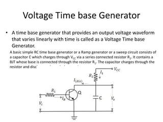
1. Time Base Generators /
Sweep Circuits
Dr. Sarmista Sengupta
Asst. Prof., Dept. of ECE
Techno Main Salt Lake
2. What is a Time Base Generator?
• An Electronic generator that generates the high frequency
saw tooth waves can be termed as a Time Base Generator.
It can also be understood as an electronic circuit which
generates an output voltage or current waveform, a portion
of which varies linearly with time. The horizontal velocity
of a time base generator must be constant.
• To display the variations of a signal with respect to time on
an oscilloscope, a voltage that varies linearly with time, has
to be applied to the deflection plates. This makes the signal
to sweep the beam horizontally across the screen. Hence
the voltage is called as Sweep Voltage. The Time Base
Generators are called as Sweep Circuits.
3. Features
• To generate a time base waveform in a CRO or a picture tube, the
deflecting voltage increases linearly with time. Generally, a time
base generator is used where the beam deflects over the screen
linearly and returns to its starting point. This occurs during the
process of Scanning. A cathode ray tube and also a picture tube
works on the same principle. The beam deflects over the screen
from one side to the other (generally from left to right) and gets
back to the same point.
• This phenomenon is termed as Trace and Retrace. The deflection of
beam over the screen from left to right is called as Trace, while the
return of the beam from right to left is called as Retrace or Fly back.
Usually this retrace is not visible. This process is done with the help
of a saw tooth wave generator which sets the time period of the
deflection with the help of RC components used.
4. Parts of a saw-tooth wave
In the above signal, the time during which the output increases linearly is called as Sweep Time
(TS) and the time taken for the signal to get back to its initial value is called as Restoration
Time or Fly back Time or Retrace Time (Tr). Both of these time periods together form the Time
period of one cycle of the Time base signal.
Actually, this Sweep voltage waveform we get is the practical output of a sweep circuit whereas
the ideal output has to be the saw tooth waveform shown in the above figure.
5. Types of Time base Generators
• Voltage Time Base Generators − A time base
generator that provides an output voltage
waveform that varies linearly with time is called
as a Voltage Time base Generator.
• Current Time Base Generator − A time base
generator that provides an output current
waveform that varies linearly with time is called
as a Current Time base Generator.
• Applications: Time Base Generators are used in
CROs, televisions, RADAR displays, precise time
measurement systems, and time modulation.
6. Voltage Time base Generator
• A time base generator that provides an output voltage waveform
that varies linearly with time is called as a Voltage Time base
Generator.
A basic simple RC time base generator or a Ramp generator or a sweep circuit consists of
a capacitor C which charges through VCC via a series connected resistor R2. It contains a
BJT whose base is connected through the resistor R1. The capacitor charges through the
resistor and discharges through the transistor.
7. Working Principle
• By the application of a positive going voltage pulse, the
transistor Q turns ON to saturation and the capacitor rapidly
discharges through Q and R1 to VCE (sat). When the input pulse
ends, Q switches OFF and the capacitor C starts charging and
continues to charge until the next input pulse. This process
repeats as shown in the waveform below.
8. Working Principle
• When the transistor turns ON it provides a low
resistance path for the capacitor to discharge
quickly. When the transistor is in OFF
condition, the capacitor will charge
exponentially to the supply voltage VCC,
according to the equation
V0=VCC[1−exp(−t/RC)]
9. Current Time base Generator
• A time base generator that provides an output current waveform
that varies linearly with time is called as a Current Time base
Generator.
A basic simple RC time base generator or a Ramp generator or a sweep circuit
consists of a common-base configuration transistor and two resistors, having
one in emitter and another in collector. The VCC is given to the collector of the
transistor. The circuit diagram of a basic ramp current generator is as shown
here under.
10. Working Principle
• As the input voltage Vi is applied at the base of the transistor,
it appears at the emitter which produces the emitter current
iE and this increases linearly as Vi increase from zero to its
peak value. The collector current increases as the emitter
current increases, because iC is closely equal to iE.
• The instantaneous value of load current is
iC≈(vi−VBE)/RE
11. Bootstrap Time Base Generator
• A bootstrap sweep generator is a time base
generator circuit whose output is fed back to
the input through the feedback. This will
increase or decrease the input impedance of
the circuit. This process of bootstrapping is
used to achieve constant charging current.
12. Miller Sweep Generator
• The Miller time base generator circuit consists of a
switch and a timing circuit in the initial stage, whose
input is taken from the Schmitt gate generator
circuit. The amplifier section is the following one
which has three stages, first being an emitter
follower, second an amplifier and the third one is
also an emitter follower.