2
GENERATION OF HIGHD.C VOLTAGE
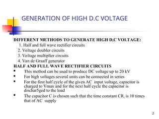
DIFFERENT METHODS TO GENERATE HIGH D,C VOLTAGE:
1. Half and full wave rectifier circuits
2. Voltage doubler circuits
3. Voltage multiplier circuits
4. Van de Graaff generator
HALF AND FULL WAVE RECTIFIER CIRCUITS
This method can be used to produce DC voltage up to 20 kV
For high voltages several units can be connected in series
For the first half cycle of the given AC input voltage, capacitor is
charged to Vmax and for the next half cycle the capacitor is
dischar5ged to the load
The capacitor C is chosen such that the time constant CRl is 10 times
that of AC supply
3.
3
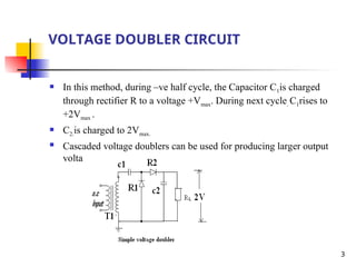
VOLTAGE DOUBLER CIRCUIT
In this method, during –ve half cycle, the Capacitor C1is charged
through rectifier R to a voltage +Vmax. During next cycle. C1rises to
+2Vmax .
C2.is charged to 2Vmax.
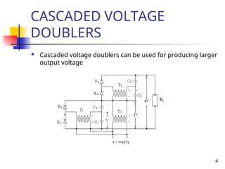
Cascaded voltage doublers can be used for producing larger output
voltage
5
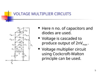
VOLTAGE MULTIPLIER CIRCUITS
Here n no. of capacitors and
diodes are used.
Voltage is cascaded to
produce output of 2nVmax .
Voltage multiplier circuit
using Cockcroft-Walton
principle can be used.
6.
6
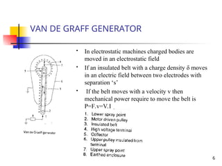
VAN DE GRAFFGENERATOR
In electrostatic machines charged bodies are
moved in an electrostatic field
If an insulated belt with a charge density δ moves
in an electric field between two electrodes with
separation ‘s’
If the belt moves with a velocity v then
mechanical power require to move the belt is
P=F.v=V.I
7.
7
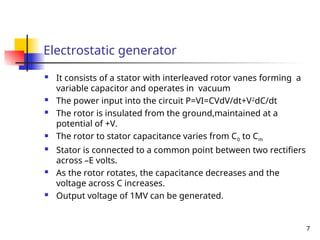
Electrostatic generator
Itconsists of a stator with interleaved rotor vanes forming a
variable capacitor and operates in vacuum
The power input into the circuit P=VI=CVdV/dt+V2
dC/dt
The rotor is insulated from the ground,maintained at a
potential of +V.
The rotor to stator capacitance varies from C0 to Cm
Stator is connected to a common point between two rectifiers
across –E volts.
As the rotor rotates, the capacitance decreases and the
voltage across C increases.
Output voltage of 1MV can be generated.
8.
8
GENERATION OF HIGH
ALTERNETINGVOLTAGES
When test voltage requirements are less than about 300
kV,a single transformer can be used.
Each transformer unit consists of low,high and meter
winding.
Series connection of the several units of transformers used
to produce very high voltage.
9.
9
CASCADE TRANSFORMERS
Firsttransformer is at ground potential along with its tank.The 2nd
transformer is kept on insulators and maintained at a potential of V2.
The high voltage winding of the 1st
unit is connected to the tank of the
2nd
unit,the low voltage winging of this unit is supplied from the
excitation winding of the 1st
transformer,which is in series with the
high voltage winding of the 1st
transformer at its high voltage end.
The rating of the excitation winding is same as that of low voltage
winding.3rd
transformer is kept on insulator above the ground at a
potential of 2V2.output of 3 stage is 3V2.
The rating of the low voltage winding of 230 or 400 Vcan be used to
produce 3.3 kV,6.6 kV or 11 kV.
11
GENERATION OF HIGHAC
VOLTAGE
Cascade transformer with isolating
transformer for excitation
12.
12
GENERATION OF HIGHFREQUENCY
A.C HIGH VOLTAGES
High frequency high voltage damped oscillations are needed
which need high voltage high frequency transformer which
is a Tesla coil.
Tesla coil is a doubly tuned resonant circuit,primary voltage
rating is 10 kV and secondary voltage rated from 500 to
1000 kV.
The primary is fed from DC or AC supply through C1.A
spark gap G connected across the primary is triggered at V1
which induces a high self excitation in the secondary.The
windings are tuned to a frequency of 10 to 100 kHz.
13.
13
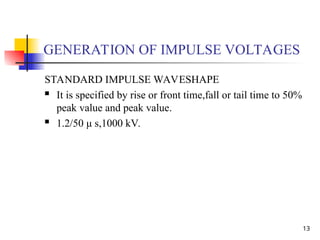
GENERATION OF IMPULSEVOLTAGES
STANDARD IMPULSE WAVESHAPE
It is specified by rise or front time,fall or tail time to 50%
peak value and peak value.
1.2/50 μ s,1000 kV.
14.
14
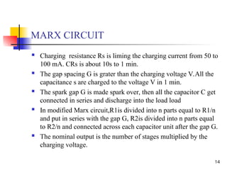
MARX CIRCUIT
Chargingresistance Rs is liming the charging current from 50 to
100 mA. CRs is about 10s to 1 min.
The gap spacing G is grater than the charging voltage V.All the
capacitance s are charged to the voltage V in 1 min.
The spark gap G is made spark over, then all the capacitor C get
connected in series and discharge into the load load
In modified Marx circuit,R1is divided into n parts equal to R1/n
and put in series with the gap G, R2is divided into n parts equal
to R2/n and connected across each capacitor unit after the gap G.
The nominal output is the number of stages multiplied by the
charging voltage.
15.
15
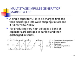
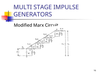
MULTISTAGE IMPULSE GENERATOR
MARXCIRCUIT
A single capacitor C1 is to be charged first and
then discharged into wave shaping circuits and
it is limited to 200 kV
For producing very high voltages a bank of
capacitors are charged in parallel and then
discharged in series.
17
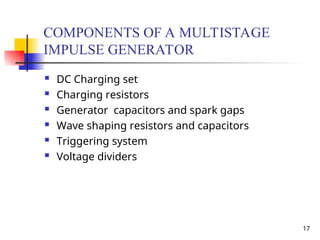
COMPONENTS OF AMULTISTAGE
IMPULSE GENERATOR
DC Charging set
Charging resistors
Generator capacitors and spark gaps
Wave shaping resistors and capacitors
Triggering system
Voltage dividers
18.
18
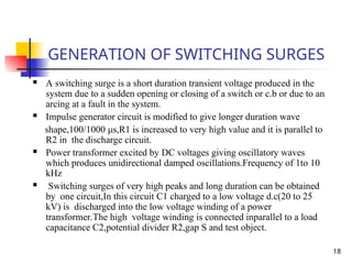
GENERATION OF SWITCHINGSURGES
A switching surge is a short duration transient voltage produced in the
system due to a sudden opening or closing of a switch or c.b or due to an
arcing at a fault in the system.
Impulse generator circuit is modified to give longer duration wave
shape,100/1000 μs,R1 is increased to very high value and it is parallel to
R2 in the discharge circuit.
Power transformer excited by DC voltages giving oscillatory waves
which produces unidirectional damped oscillations.Frequency of 1to 10
kHz
Switching surges of very high peaks and long duration can be obtained
by one circuit,In this circuit C1 charged to a low voltage d.c(20 to 25
kV) is discharged into the low voltage winding of a power
transformer.The high voltage winding is connected inparallel to a load
capacitance C2,potential divider R2,gap S and test object.
19.
19
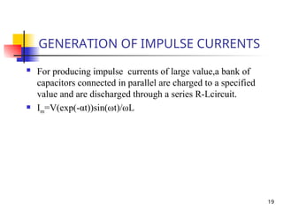
GENERATION OF IMPULSECURRENTS
For producing impulse currents of large value,a bank of
capacitors connected in parallel are charged to a specified
value and are discharged through a series R-Lcircuit.
Im=V(exp(-αt))sin(ωt)/ωL
20.
20
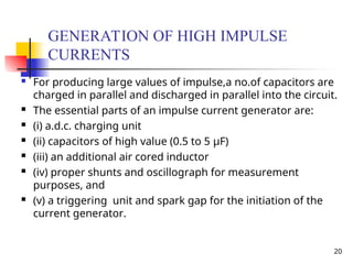
GENERATION OF HIGHIMPULSE
CURRENTS
For producing large values of impulse,a no.of capacitors are
charged in parallel and discharged in parallel into the circuit.
The essential parts of an impulse current generator are:
(i) a.d.c. charging unit
(ii) capacitors of high value (0.5 to 5 μF)
(iii) an additional air cored inductor
(iv) proper shunts and oscillograph for measurement
purposes, and
(v) a triggering unit and spark gap for the initiation of the
current generator.
21.
21
TRIPPING AND CONTROLOF IMPULSE
GENERATORS
In large impulse generators, the spark gaps are
generally sphere gaps or gaps formed by
hemispherical electrodes.
The gaps are arranged such that sparking of one
gap results in automatic sparking of other gaps as
overvoltage is impressed on the other.
A simple method of controlled tripping consists of
making the first gap a three electrode gap and
firing it from a controlled source.
22.
22
TRIPPING AND CONTROLOF IMPULSE
GENERATORS
The first stage of the impulse generator is fitted with a three
electrode gap, and the central electrode is maintained at a
potential in between that of the top and the bottom electrodes
with the resistors R1 and RL.
The tripping is initiated by applying a pulse to the thyration G
by closing the switch S.
C produces an exponentially decaying pulse of positive polarity.
The Thyraton conducts on receiving the pulse from the switch S
and produces a negative pulse through the capacitance C1 at
central electrode.
Voltage between central electrode and the top electrode those
above sparking potential and gap contacts.
23.
23
TRIPPING CIRCUIT USINGA TRIGATRON
This requires much smaller voltage for operation
compared to the three electrode gap.
A trigatron gap consists of a high voltage spherical
electrode, an earthed main electrode of spherical shape,
and a trigger electrode through the main electrode.
Tripping of the impulse generator is effected by a trip
pulse which produces a spark between the trigger
electrode and the earthed sphere.
Due to space charge effects and distortion of the field in
the main gap, spark over of the main gap occurs and it
is polarity sensitive.