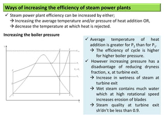
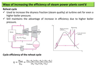
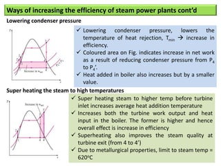
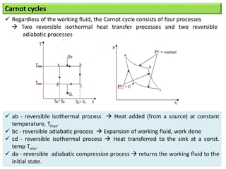
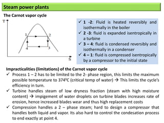
- The Carnot cycle consists of four processes: two reversible isothermal heat transfer processes and two reversible adiabatic processes.
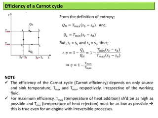
- The efficiency of the Carnot cycle depends only on the source and sink temperatures, irrespective of the working fluid. Maximum efficiency is achieved with highest source temperature and lowest sink temperature.
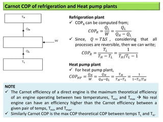
- The Carnot COP is the maximum theoretical COP between two temperatures for refrigeration or heat pump cycles. No real system can exceed the Carnot COP.


![Other criteria used in comparing steam power plants
Efficiency ratio
Ratio of the actual cycle efficiency to Rankine efficiency
Sh’d be as large as possible, the closer it is to 1.0 , the less is the energy wasted
against irreversibilities.
Work ratio
𝑊𝑜𝑟𝑘 𝑟𝑎𝑡𝑖𝑜 =
𝑁𝑒𝑡 𝑤𝑜𝑟𝑘
𝑔𝑟𝑜𝑠𝑠 𝑤𝑜𝑟𝑘
=
𝑊𝑜𝑟𝑘 𝑡𝑢𝑟𝑏𝑖𝑛𝑒−𝑊𝑜𝑟𝑘 𝑝𝑢𝑚𝑝
𝑊𝑜𝑟𝑘 𝑡𝑢𝑟𝑏𝑖𝑛𝑒
Specific steam consumption (ssc)
It relates the plant output to the steam that is flowing through it
Amount of steam flow also indicates the size of the components measure of
relative sizes of the steam plants.
𝑠𝑠𝑐 =
3600
𝑊𝑛𝑒𝑡
, where Wnet – network output [kJ/kg]](https://image.slidesharecdn.com/lecture5-230604090717-1ea6646e/85/Lecture-5-pptx-12-320.jpg)