1
Thermal Stresses
Student Name: Rawa Abdullah Taha
Class: two – Group A
Course Title: Fundamentals of Design
Department: Mechanic and Mechatronics
College of Engineering
Salahaddin University - Erbil
Academic Year 2019 – 2020
2
ABSTRACT
I will discuss the thermal stresses topic in general, which I will discuss in
detail in what field it works, and I have shown several different examples
and images to better understand the topic, which is an important topic for
Mechanical Engineering in all the engineering departments that specialize
in it. In heat and movement and strength. Many physically demanding
occupations in both developed and developing economies involve
exposure to extreme thermal environments that can affect work capacity
and ultimately health. Thermal extremes may be present in either an
outdoor or an indoor work environment, and can be due to a combination
of the natural or artificial ambient environment, the rate of metabolic heat
generation from physical work, processes specific to the workplace (e.g.,
steel manufacturing), or through the requirement for protective clothing
impairing heat dissipation.
3
TABLE OF CONTENTS
Abstract 2
Table of Contents 3
Introduction 4
Introduction 5
Introduction 6
Background&Review 7
Background&Review 8
Background&Review 9
Background&Review 10
Methods 10
Methods 11
Methods 12
Theory / design 13
Theory / design 14
Theory / design 15
Theory / design 16
Conclusion 17
References 18
4
INTRODUCTION
In mechanics and thermodynamics, thermal stress is
mechanical stress formed by any change in temperature of a material.
These stresses can lead to fracturing or plastic deformation depending on
the other movables of heating, which include material types and
constraints.Temperature gradients,Thermal expansion or contraction and
thermal shocks are things that can lead to thermal stress. This type of
stress is highly dependent on the thermal expansion Cofficient which
varies from material to material. In general, the greater the temperature
change, the higher the level of stress that can occur. Thermal shock can
result from a rapid change in temperature, resulting in cracking or
shattering.
Temperature gradients:
When a material is quickly heated or cooled, the surface and internal
temperature will have a difference in temperature. Quick heating or
cooling causes localized areas of thermal expansion or contraction, this
contained movement of material causes thermal stresses. Imagine heating
a cylinder, first the surface rises in temperature and the center remains the
same initial temperature. After some time the center of the cylinder will
reach the similar temperature as the surface. During the heat up the
surface is relatively hotter and will expand more than the center. An
example of this is dental fillings can cause thermal stress in a person's
mouth. Sometimes dentists use dental fillings with different thermal
expansion coefficients than tooth enamel, the fillings will expand faster
than the enamel and cause pain in a person's mouth.
Thermal expansion or contraction:
Material will expand or contract be contingent on the material's thermal
expansion coefficient. As long as the material is free to move, the
material can expand or contract freely without making stresses. Once this
material is attached to a rigid body at multiple locations, thermal stresses
can be created in the geometrically constrained region. This stress is
calculated by multiplying the change in temperature, material's thermal
5
expansion coefficient and
material's Young's
modulus (see formula
below) . E is Young's
modulus, α is thermal
expansion coefficient, To
is temperature original,
and Tf is the final
temperature.
Figure(1)
Thermal-Stress and Thermal-Deflection analyses are an important subset
of general finite element analysis (FEA) modeling. Such analyses are
common in the development of rocket motors, ASME pressure vessels,
electronics (PCB), electronic systems (automotive lamp systems),
composite curing mandrels, generators, satellites and etc. This technical
discussion will present the basic principles of linear, thermal-stress and
thermal-deflection analysis. We say “linear” since it is starting point if
one events to move forward with more complex type of analyses. For this
seminar we will use thermal-stress to cover any type of mechanical
behavior, stress or deflection introduced by a fixed temperature rise
(delta) or an induced temperature gradient. The resulting strain from this
temperature load is based on the material’s coefficient of thermal
expansion (CTE). The development of stress or deflection within the
structure due to this fixed strain and/or variable strain is dependent upon
many factors that will be discussed with easyto-follow basic examples.
Figure(2)
6
With this background, the creation of temperature loads will be discussed
using simple boundary conditions or running a steady-state conduction
analysis to map out an imposed temperature gradient. These thermal
results will then be converted to a temperature load for the thermal-stress
or –deflection analyses. This seminar will close with several examples of
thermal-stress work that we have done at Predictive Engineering.
If specific temperatures are known at boundaries, a steady-state
conduction analysis can be used to map these temperatures into the
structure. Likewise, if the geometry is relatively simple, Data Surfaces
can directly create the temperature field to drive the structural load case.
In this example, we’ll show how to do a passing thermal analysis and
convert the temperature results into a structural load case.
Figure(3)
7
BACKGROUND & REVIEW
In the field of thermal stresses we have a set of experiences and research
done on topics that have been researched and worked on by several
universities around the world and students around the world, some of
which we discuss here such as that,
Experimental study of thermal stresses in a bonded joint:
Composite patches are often used to reinforce damaged aeronautical
structures. Such structures are subjected to temperature changes which
may cause a thermal stress distribution to appear in the bonded joint
between composite and metallic substrate. This phenomenon is due to the
alteration of Coefficient of Thermal Expansion (CTE) between the two
adherends. The aim of this work is to perform full-field measurements in
order to characterize the effect of a temperature change in a
metal/composite specimen and to deduce the resulting shear stress
distribution in the bonded joint. The patched specimen under study is
heated. The temperature change is measured on one side of the specimen
with an infrared camera and the displacement distribution is obtained on
the other side using a CCD camera and a relevant image processing . It is
possible to deduce the thermal shear stress distribution in the adhesive
using these two types of measurement if they are processed with a
suitable model,and if the specimen is assumed to be symmetric with
respect to its mid-plane. The experimental set-up is presented below. The
first effects
obtained are
discussed and
the effect of
temperature
changes on the
displacement/s
train fields is
experimentally
evidenced.
Figure(4)
8
The aim of this test is to measure both the thermal and the displacement
fields during the same experiment. For this purpose, a CCD camera and
an infrared camera are placed in front of each side of the specimen to
measure the displacement and temperature fields,
respectively (see Figure 4).
Specimen: The specimen is made of 2024T3 aluminum. Its length, width
and thickness are 340 mm, 70 mm and 3 mm, respectively. Aluminum is
supposed to be linear isotropic elastic (Es = 73.8 GPa, νs = 0.33,
αs=23.6e-6 K-1). Composite patches are bonded on each side of the
specimen. Their length, width and thickness are 70 mm, 70 mm and 0.5
mm, respectively. The composite is assumed to be orthotropic and elastic
(Ex = 181 GPa, Ey = 10.3 GPa, νxy = 0.28, Gxy = 7 GPa, αx=0.02e-6 K-
1 , ay=22.5e-6 K-1). The adhesive used is the Redux 312 supplied by
Hexcel. It is assumed to be thermoelastic. Its shear modulus depends on
the temperature, as shown in Figure 5 where the real part of the shear
modulus G’ measured with a suitable rheometer is shown. The thickness
of each of the two adhesive layers is 0.15 mm. The composite patches are
not tapered near the free edges. This enables us to compare the results
observed with some simple analytical models .
Figure(5)
9
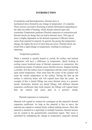
Measurement of the displacement/strain field : The grid method is used to
obtain the displacement field on the surface of the patch. This method has
been developed by Surrel. It is based on the analysis of the deformation
of a grid bonded on the surface of the specimen prior to testing .A camera
captures the light intensities on the surface before and after loading.
Images are processed by means of an appropriate algorithm [1] [2], which
detects very slight variations of the grid pitch caused by the surface
deformation. This algorithm calculates the displacement field throughout
the surface under investigation. The grid used exhibits a period of 5 lines
/ mm. The 12 bit camera used exhibits 1376 x 1040 pixels. The distance
between the camera and the specimen is adjusted in such a way that 5
pixels are used to discretize one period of the grid. Thus, only the upper-
left corner of the patch, corresponding to a 55 mm x 42 mm rectangle, is
observed in practice. 9 pixels are used to measure the displacement at a
given point. Since one pixel corresponds to 40 µm, spatial resolution is
equal to 360 µm.
Measurement of the temperature field :The second side of the specimen is
painted with a black spray to obtain the greatest emissivity as possible
and the camera is set to have a global overview of the temperature field
on the upper surface of the composite patch. The infrared camera used is
a CEDIP Jade. Its sensor exhibits 320 x 240 pixels. The thermal
resolution of the camera is 0.02 K. The thermal loading is applied with
four Minco 9.8 Ω thermal resistances deposited on each side of the
specimen, at each end of the composite patches to obtain a symmetric
thermal field.
Results : Temperature field A typical temperature field on the upper side
of the composite is presented in Figure 6(a) and the distribution of the
minimum, maximum and average temperatures versus time is presented
in Figure 6 (b). This is the absolute temperature in °C. The temperature
variation is deduced by subtracting the initial temperature which is equal
to the room temperature: 20°C. The temperature field is not strictly
homogeneous because the heat flux is transmitted by the four resistances
located at the ends of the patch. Hence, there is a variation of about 10°C
between the ends and the center of the patch because of the heat exchange
10
with ambient air. For this first approach however, the experimental results
will be compared to the analytical results obtained with a constant
temperature variation equal to the average temperature variation which is
measured.
Figure(6)
METHODS
Design tasks often involve parts made of more than one
material. Sometimes the materials are bonded together and at other times
they are not. Assembled parts may look like they consist of bonded parts
simply because appear to be touching. However, analysis software
assumes that adjacent parts are not bonded or even in contact unless the
user specifically establishes such relations. To illustrate these concepts
consider the common elementary physics experiment of uniformly
heating two bonded beams made of materials having different
coefficients of thermal
expansion, α. You probably recall
that when subject to a uniform
temperature change, ∆T, the bonded
beam takes on a state of constant
curvature, of radius r, even though
there are no externally applied
forces. Denote the unstressed free
length as L, and the final end deflection as δ(see Figure 7) Figure(7)
11
Temperature limits for different conductor materials
Table 1
θkad
°C
adθ
°C
Constructive typeMaterialNo.
20060Simple or painted conductorCopper1
17080Overhead conductor
16065Paper insulated cable, 3 kV
12065Paper insulated cable, 6 kVCopper2
12055Paper insulated cable, 20 kV
10045Paper insulated cable, > 20 kV
18060Simple or painted conductorAluminum3
13080Overhead conductor
16065Paper insulated cable, 3kV
12065Paper insulated cable, 6 kV
12055Paper insulated cable, 20 kV
Thermal stresses of the electrical equipment The conversion of
electromagnetic energy into thermal energy occurs in the active materials
(conductors, core irons and electrical parts). The thermal energy is carried
out by heat transfer, the heat flow always being directed from the higher
temperature areas to the lower temperature areas until the temperatures
are equal. The heat transfer is achieved by conduction, convection and
radiation. The electrical conductors of the equipment ensure the electrical
conduction and these parts are subject of different intensities of thermal
stresses. In general, the conductors consist of homogeneous parts bar
shaped, whitch are heated by the action of current that passes through
them. In order to ensure thermal stability of electrical equipment, it is
required that the final value θk of the temperature, at the moment tk, to be
under the rated limit for the nominal currents θad and under θkad for fault
currents, as in table 1. The transient heating study of the conductive paths
for long-term thermal stress will be based on the following simplifying
assumptions: conductive path is homogeneous, the global thermal
transmissivity and specific heat are considered invariant with
temperature, temperature variation along the conductor is zero and,
12
ambient temperature has a constant value. With these the general
equation of the conductive paths thermal stress as in is :
(1)
where ρ0 , and γ are the resistivity and the conductor material density at 0
o C, αR is the coefficient of the resistivity variation with the temperature,
J is the current density, c is the specific heat, αt is the global thermal
transmissivity, Ap is the legth of the perimeter corresponding to the
transversal section s, is the conductive path’s overtemperature. It will be
noted:
(2)
Taking into account that the critic value of the current density is:
(3)
13
THEORY / DESIGN
Reliability of Thermal strain and stresses in simple bars:
Whenever there is some increase or decrease in the temperature of a
body, it causes the body to expand or contract. A little consideration will
show that if the body is allowed to expand or contract freely, with the rise
or fall of the temperature, no stresses are induced in the body. But if the
deformation of the body is prevented, some stresses are induced in the
body. Such stresses are called thermal stresses or temperature stresses.
The corresponding strains are called the thermal strains or temperature
strains. Reliability is used for developing the equipment manufacturing
and delivery to the user. A reliable system is one which operates
according to our expectations. Reliability of a system is the probability
that a system perform its intended purpose for a given period of time
under stated environment conditions. In some cases system failures occur
due to certain type of stresses acting on them. These types of system are
called stress dependent models of reliability. These models nowadays
studied in many branches of science such as Engineering, Medicine, and
Pharmaceutical Industries etc..In assessing system reliability it is first
necessary to define and categorize different modes of system failures. It is
difficult to define failure in unambiguous forms. However a system’s
performance can deteriorate gradually over time and sometimes there is
only a fine line between systems success and system failure. Once the
system function and failure modes are explicitly stated reliability can be
precisely quantified by probability statements . The thermal stresses or
strains bar may be found out as discussed below:
The thermal stresses or strains may be found out first by finding out
amount of deformation due change in temperature, and then by finding
out thermal strain due to the deformation. The thermal stress may now be
found out from the thermal strain as usual. Now consider a body
subjected to an increase in temperature.
14
Let
l=original length of the body,
𝜃=increase of temperature and
𝛼=coefficient of linear expansion
E=modulus of elasticity (young’s modulus)
We know that the increase in length due to increase of temperature
𝛿𝑙=𝑙. 𝛼. 𝜃, (4)
If the ends of the bar are fixed to rigid supports, so that its expansion is
prevented, then compressive strain induced in the bar. Here some
Figure(8)
Figure(9)
15
Figure(10)
Figure(11)
Here is a example I solve it :
Q1/ A rigid horizontal bar of negligible mass is connected to two rods as
shown in the figure(12). If the system is initially stress-free; determine
the temperature change that will cause a tensile stress of 60 MPa in the
steel rod. Assume Es=200 GPa, s=11.7 m/m°C and As=900 mm2 ,
Eb=83 GPa, b=18.9m/m°C, Ab=1200 mm2 .
Figure(12)
16
Solution:
𝜎𝑠 = 𝐹𝑠/𝐴𝑠 → 𝐹𝑠 = 𝐴𝑠𝜎𝑠
Statics
∑ 𝑀𝐴 = 0: 𝐹𝑠 ∗ 5 = 𝐹𝑏 ∗ 2
∴ 𝐹𝑏 = 5/ 2 𝐹𝑠 (5)
Since 𝜎𝑠 = 60 MPa, then 𝐹𝑠 = 𝐴𝑠𝜎𝑠 = 900 × 10−6
× 60 × 106
= 54 kN
Use equation (1), 𝐹𝑏 = 135 kN
Deformation
𝛿𝑠/5 = 𝛿𝑏/2 → 𝛿𝑏 = 5/2 𝛿s
∆𝑇 = 9.2°C
17
CONCLUSION
In this article I have discussed the poison far, long and briefly about
thermal stresses, and I have brought up a number of examples of various
studies that the reader can benefit from, and I have illustrated my
example later. And then I said that the research was done on my subject
so I came to the conclusion that thermal stress is a very important topic in
my life so most of the engineering departments work with it. Overall,
while there is a large body of knowledge concerning the physiological
effects of thermal stress, work into direct occupational applications such
as developing physical employment standards can be considered to be in
its infancy. Physical employment standards are largely nonexistent in
most cold-related occupations. In hot environments, current standards
tend towards being based on isolated factors – such as aerobic fitness –
that indirectly contribute to improved work performance but yet may not
be the sole or key limiter in the majority of situations. Physical
employment standards are currently limited to firefighting, military, and
mining occupations, Overall, while there is a large body of knowledge
concerning the physiological effects of thermal stress, work into direct
occupational applications such as developing physical employment
standards can be considered to be in its infancy. Physical employment
standards are largely nonexistent in most cold-related occupations. In hot
environments, current standards tend towards being based on isolated
factors – such as aerobic fitness – that indirectly contribute to improved
work performance but yet may not be the sole or key limiter in the
majority of situations. Physical employment standards are currently
limited to firefighting, military, and mining occupations.
18
REFERENCES
[1] Armstrong, L.E., and Maresh, C.M. 1991. The induction and decay of
heat acclimatisation in trained athletes. Sports Med. 12(5): 302–312. doi
[2] Abu-Bakr Iris (2007): Reliability Analysis of Simply Supported Steel
Beams
[3] R.S. KHURMI, Strength of Materials [Mechanical of Solids], S.
Chand Publications
[4] T.S.Uma Maheswari (1991): Studies on some Stress-Strength
reliability models, Ph.D.Thesis, Kakatiya University, Warangal.
[5] Beer.F.P. , Johnston.E.R. (1992) mechanics of the material , 2nd
edition. McGraw-Hill, Chapter 2.10
[6] . E. Suhir, Effect of Initial Curvature on Low Temperature
Microbending in Optical Fibers, IEEE/OSA Journal of Lightwave
Technology, vol. 6, no. 8, pp. 1321–1327, 1988.
[7] D. Ingman and E. Suhir, Optical Fiber with Nano-Particle Overclad,
U.S. Patent #7,162,138 B2, 2007.
[8] Y. Zhang, E. Suhir, C. Gu, Carbon Nanotubes/Nanofibers as Thermal
Interface Materials (TIMs): Physical/Mechanical Properties and
Requirements, Inveted Review Paper, Taiwan, to be published

Thermal stresses

  • 1.
    1 Thermal Stresses Student Name:Rawa Abdullah Taha Class: two – Group A Course Title: Fundamentals of Design Department: Mechanic and Mechatronics College of Engineering Salahaddin University - Erbil Academic Year 2019 – 2020
  • 2.
    2 ABSTRACT I will discussthe thermal stresses topic in general, which I will discuss in detail in what field it works, and I have shown several different examples and images to better understand the topic, which is an important topic for Mechanical Engineering in all the engineering departments that specialize in it. In heat and movement and strength. Many physically demanding occupations in both developed and developing economies involve exposure to extreme thermal environments that can affect work capacity and ultimately health. Thermal extremes may be present in either an outdoor or an indoor work environment, and can be due to a combination of the natural or artificial ambient environment, the rate of metabolic heat generation from physical work, processes specific to the workplace (e.g., steel manufacturing), or through the requirement for protective clothing impairing heat dissipation.
  • 3.
    3 TABLE OF CONTENTS Abstract2 Table of Contents 3 Introduction 4 Introduction 5 Introduction 6 Background&Review 7 Background&Review 8 Background&Review 9 Background&Review 10 Methods 10 Methods 11 Methods 12 Theory / design 13 Theory / design 14 Theory / design 15 Theory / design 16 Conclusion 17 References 18
  • 4.
    4 INTRODUCTION In mechanics andthermodynamics, thermal stress is mechanical stress formed by any change in temperature of a material. These stresses can lead to fracturing or plastic deformation depending on the other movables of heating, which include material types and constraints.Temperature gradients,Thermal expansion or contraction and thermal shocks are things that can lead to thermal stress. This type of stress is highly dependent on the thermal expansion Cofficient which varies from material to material. In general, the greater the temperature change, the higher the level of stress that can occur. Thermal shock can result from a rapid change in temperature, resulting in cracking or shattering. Temperature gradients: When a material is quickly heated or cooled, the surface and internal temperature will have a difference in temperature. Quick heating or cooling causes localized areas of thermal expansion or contraction, this contained movement of material causes thermal stresses. Imagine heating a cylinder, first the surface rises in temperature and the center remains the same initial temperature. After some time the center of the cylinder will reach the similar temperature as the surface. During the heat up the surface is relatively hotter and will expand more than the center. An example of this is dental fillings can cause thermal stress in a person's mouth. Sometimes dentists use dental fillings with different thermal expansion coefficients than tooth enamel, the fillings will expand faster than the enamel and cause pain in a person's mouth. Thermal expansion or contraction: Material will expand or contract be contingent on the material's thermal expansion coefficient. As long as the material is free to move, the material can expand or contract freely without making stresses. Once this material is attached to a rigid body at multiple locations, thermal stresses can be created in the geometrically constrained region. This stress is calculated by multiplying the change in temperature, material's thermal
  • 5.
    5 expansion coefficient and material'sYoung's modulus (see formula below) . E is Young's modulus, α is thermal expansion coefficient, To is temperature original, and Tf is the final temperature. Figure(1) Thermal-Stress and Thermal-Deflection analyses are an important subset of general finite element analysis (FEA) modeling. Such analyses are common in the development of rocket motors, ASME pressure vessels, electronics (PCB), electronic systems (automotive lamp systems), composite curing mandrels, generators, satellites and etc. This technical discussion will present the basic principles of linear, thermal-stress and thermal-deflection analysis. We say “linear” since it is starting point if one events to move forward with more complex type of analyses. For this seminar we will use thermal-stress to cover any type of mechanical behavior, stress or deflection introduced by a fixed temperature rise (delta) or an induced temperature gradient. The resulting strain from this temperature load is based on the material’s coefficient of thermal expansion (CTE). The development of stress or deflection within the structure due to this fixed strain and/or variable strain is dependent upon many factors that will be discussed with easyto-follow basic examples. Figure(2)
  • 6.
    6 With this background,the creation of temperature loads will be discussed using simple boundary conditions or running a steady-state conduction analysis to map out an imposed temperature gradient. These thermal results will then be converted to a temperature load for the thermal-stress or –deflection analyses. This seminar will close with several examples of thermal-stress work that we have done at Predictive Engineering. If specific temperatures are known at boundaries, a steady-state conduction analysis can be used to map these temperatures into the structure. Likewise, if the geometry is relatively simple, Data Surfaces can directly create the temperature field to drive the structural load case. In this example, we’ll show how to do a passing thermal analysis and convert the temperature results into a structural load case. Figure(3)
  • 7.
    7 BACKGROUND & REVIEW Inthe field of thermal stresses we have a set of experiences and research done on topics that have been researched and worked on by several universities around the world and students around the world, some of which we discuss here such as that, Experimental study of thermal stresses in a bonded joint: Composite patches are often used to reinforce damaged aeronautical structures. Such structures are subjected to temperature changes which may cause a thermal stress distribution to appear in the bonded joint between composite and metallic substrate. This phenomenon is due to the alteration of Coefficient of Thermal Expansion (CTE) between the two adherends. The aim of this work is to perform full-field measurements in order to characterize the effect of a temperature change in a metal/composite specimen and to deduce the resulting shear stress distribution in the bonded joint. The patched specimen under study is heated. The temperature change is measured on one side of the specimen with an infrared camera and the displacement distribution is obtained on the other side using a CCD camera and a relevant image processing . It is possible to deduce the thermal shear stress distribution in the adhesive using these two types of measurement if they are processed with a suitable model,and if the specimen is assumed to be symmetric with respect to its mid-plane. The experimental set-up is presented below. The first effects obtained are discussed and the effect of temperature changes on the displacement/s train fields is experimentally evidenced. Figure(4)
  • 8.
    8 The aim ofthis test is to measure both the thermal and the displacement fields during the same experiment. For this purpose, a CCD camera and an infrared camera are placed in front of each side of the specimen to measure the displacement and temperature fields, respectively (see Figure 4). Specimen: The specimen is made of 2024T3 aluminum. Its length, width and thickness are 340 mm, 70 mm and 3 mm, respectively. Aluminum is supposed to be linear isotropic elastic (Es = 73.8 GPa, νs = 0.33, αs=23.6e-6 K-1). Composite patches are bonded on each side of the specimen. Their length, width and thickness are 70 mm, 70 mm and 0.5 mm, respectively. The composite is assumed to be orthotropic and elastic (Ex = 181 GPa, Ey = 10.3 GPa, νxy = 0.28, Gxy = 7 GPa, αx=0.02e-6 K- 1 , ay=22.5e-6 K-1). The adhesive used is the Redux 312 supplied by Hexcel. It is assumed to be thermoelastic. Its shear modulus depends on the temperature, as shown in Figure 5 where the real part of the shear modulus G’ measured with a suitable rheometer is shown. The thickness of each of the two adhesive layers is 0.15 mm. The composite patches are not tapered near the free edges. This enables us to compare the results observed with some simple analytical models . Figure(5)
  • 9.
    9 Measurement of thedisplacement/strain field : The grid method is used to obtain the displacement field on the surface of the patch. This method has been developed by Surrel. It is based on the analysis of the deformation of a grid bonded on the surface of the specimen prior to testing .A camera captures the light intensities on the surface before and after loading. Images are processed by means of an appropriate algorithm [1] [2], which detects very slight variations of the grid pitch caused by the surface deformation. This algorithm calculates the displacement field throughout the surface under investigation. The grid used exhibits a period of 5 lines / mm. The 12 bit camera used exhibits 1376 x 1040 pixels. The distance between the camera and the specimen is adjusted in such a way that 5 pixels are used to discretize one period of the grid. Thus, only the upper- left corner of the patch, corresponding to a 55 mm x 42 mm rectangle, is observed in practice. 9 pixels are used to measure the displacement at a given point. Since one pixel corresponds to 40 µm, spatial resolution is equal to 360 µm. Measurement of the temperature field :The second side of the specimen is painted with a black spray to obtain the greatest emissivity as possible and the camera is set to have a global overview of the temperature field on the upper surface of the composite patch. The infrared camera used is a CEDIP Jade. Its sensor exhibits 320 x 240 pixels. The thermal resolution of the camera is 0.02 K. The thermal loading is applied with four Minco 9.8 Ω thermal resistances deposited on each side of the specimen, at each end of the composite patches to obtain a symmetric thermal field. Results : Temperature field A typical temperature field on the upper side of the composite is presented in Figure 6(a) and the distribution of the minimum, maximum and average temperatures versus time is presented in Figure 6 (b). This is the absolute temperature in °C. The temperature variation is deduced by subtracting the initial temperature which is equal to the room temperature: 20°C. The temperature field is not strictly homogeneous because the heat flux is transmitted by the four resistances located at the ends of the patch. Hence, there is a variation of about 10°C between the ends and the center of the patch because of the heat exchange
  • 10.
    10 with ambient air.For this first approach however, the experimental results will be compared to the analytical results obtained with a constant temperature variation equal to the average temperature variation which is measured. Figure(6) METHODS Design tasks often involve parts made of more than one material. Sometimes the materials are bonded together and at other times they are not. Assembled parts may look like they consist of bonded parts simply because appear to be touching. However, analysis software assumes that adjacent parts are not bonded or even in contact unless the user specifically establishes such relations. To illustrate these concepts consider the common elementary physics experiment of uniformly heating two bonded beams made of materials having different coefficients of thermal expansion, α. You probably recall that when subject to a uniform temperature change, ∆T, the bonded beam takes on a state of constant curvature, of radius r, even though there are no externally applied forces. Denote the unstressed free length as L, and the final end deflection as δ(see Figure 7) Figure(7)
  • 11.
    11 Temperature limits fordifferent conductor materials Table 1 θkad °C adθ °C Constructive typeMaterialNo. 20060Simple or painted conductorCopper1 17080Overhead conductor 16065Paper insulated cable, 3 kV 12065Paper insulated cable, 6 kVCopper2 12055Paper insulated cable, 20 kV 10045Paper insulated cable, > 20 kV 18060Simple or painted conductorAluminum3 13080Overhead conductor 16065Paper insulated cable, 3kV 12065Paper insulated cable, 6 kV 12055Paper insulated cable, 20 kV Thermal stresses of the electrical equipment The conversion of electromagnetic energy into thermal energy occurs in the active materials (conductors, core irons and electrical parts). The thermal energy is carried out by heat transfer, the heat flow always being directed from the higher temperature areas to the lower temperature areas until the temperatures are equal. The heat transfer is achieved by conduction, convection and radiation. The electrical conductors of the equipment ensure the electrical conduction and these parts are subject of different intensities of thermal stresses. In general, the conductors consist of homogeneous parts bar shaped, whitch are heated by the action of current that passes through them. In order to ensure thermal stability of electrical equipment, it is required that the final value θk of the temperature, at the moment tk, to be under the rated limit for the nominal currents θad and under θkad for fault currents, as in table 1. The transient heating study of the conductive paths for long-term thermal stress will be based on the following simplifying assumptions: conductive path is homogeneous, the global thermal transmissivity and specific heat are considered invariant with temperature, temperature variation along the conductor is zero and,
  • 12.
    12 ambient temperature hasa constant value. With these the general equation of the conductive paths thermal stress as in is : (1) where ρ0 , and γ are the resistivity and the conductor material density at 0 o C, αR is the coefficient of the resistivity variation with the temperature, J is the current density, c is the specific heat, αt is the global thermal transmissivity, Ap is the legth of the perimeter corresponding to the transversal section s, is the conductive path’s overtemperature. It will be noted: (2) Taking into account that the critic value of the current density is: (3)
  • 13.
    13 THEORY / DESIGN Reliabilityof Thermal strain and stresses in simple bars: Whenever there is some increase or decrease in the temperature of a body, it causes the body to expand or contract. A little consideration will show that if the body is allowed to expand or contract freely, with the rise or fall of the temperature, no stresses are induced in the body. But if the deformation of the body is prevented, some stresses are induced in the body. Such stresses are called thermal stresses or temperature stresses. The corresponding strains are called the thermal strains or temperature strains. Reliability is used for developing the equipment manufacturing and delivery to the user. A reliable system is one which operates according to our expectations. Reliability of a system is the probability that a system perform its intended purpose for a given period of time under stated environment conditions. In some cases system failures occur due to certain type of stresses acting on them. These types of system are called stress dependent models of reliability. These models nowadays studied in many branches of science such as Engineering, Medicine, and Pharmaceutical Industries etc..In assessing system reliability it is first necessary to define and categorize different modes of system failures. It is difficult to define failure in unambiguous forms. However a system’s performance can deteriorate gradually over time and sometimes there is only a fine line between systems success and system failure. Once the system function and failure modes are explicitly stated reliability can be precisely quantified by probability statements . The thermal stresses or strains bar may be found out as discussed below: The thermal stresses or strains may be found out first by finding out amount of deformation due change in temperature, and then by finding out thermal strain due to the deformation. The thermal stress may now be found out from the thermal strain as usual. Now consider a body subjected to an increase in temperature.
  • 14.
    14 Let l=original length ofthe body, 𝜃=increase of temperature and 𝛼=coefficient of linear expansion E=modulus of elasticity (young’s modulus) We know that the increase in length due to increase of temperature 𝛿𝑙=𝑙. 𝛼. 𝜃, (4) If the ends of the bar are fixed to rigid supports, so that its expansion is prevented, then compressive strain induced in the bar. Here some Figure(8) Figure(9)
  • 15.
    15 Figure(10) Figure(11) Here is aexample I solve it : Q1/ A rigid horizontal bar of negligible mass is connected to two rods as shown in the figure(12). If the system is initially stress-free; determine the temperature change that will cause a tensile stress of 60 MPa in the steel rod. Assume Es=200 GPa, s=11.7 m/m°C and As=900 mm2 , Eb=83 GPa, b=18.9m/m°C, Ab=1200 mm2 . Figure(12)
  • 16.
    16 Solution: 𝜎𝑠 = 𝐹𝑠/𝐴𝑠→ 𝐹𝑠 = 𝐴𝑠𝜎𝑠 Statics ∑ 𝑀𝐴 = 0: 𝐹𝑠 ∗ 5 = 𝐹𝑏 ∗ 2 ∴ 𝐹𝑏 = 5/ 2 𝐹𝑠 (5) Since 𝜎𝑠 = 60 MPa, then 𝐹𝑠 = 𝐴𝑠𝜎𝑠 = 900 × 10−6 × 60 × 106 = 54 kN Use equation (1), 𝐹𝑏 = 135 kN Deformation 𝛿𝑠/5 = 𝛿𝑏/2 → 𝛿𝑏 = 5/2 𝛿s ∆𝑇 = 9.2°C
  • 17.
    17 CONCLUSION In this articleI have discussed the poison far, long and briefly about thermal stresses, and I have brought up a number of examples of various studies that the reader can benefit from, and I have illustrated my example later. And then I said that the research was done on my subject so I came to the conclusion that thermal stress is a very important topic in my life so most of the engineering departments work with it. Overall, while there is a large body of knowledge concerning the physiological effects of thermal stress, work into direct occupational applications such as developing physical employment standards can be considered to be in its infancy. Physical employment standards are largely nonexistent in most cold-related occupations. In hot environments, current standards tend towards being based on isolated factors – such as aerobic fitness – that indirectly contribute to improved work performance but yet may not be the sole or key limiter in the majority of situations. Physical employment standards are currently limited to firefighting, military, and mining occupations, Overall, while there is a large body of knowledge concerning the physiological effects of thermal stress, work into direct occupational applications such as developing physical employment standards can be considered to be in its infancy. Physical employment standards are largely nonexistent in most cold-related occupations. In hot environments, current standards tend towards being based on isolated factors – such as aerobic fitness – that indirectly contribute to improved work performance but yet may not be the sole or key limiter in the majority of situations. Physical employment standards are currently limited to firefighting, military, and mining occupations.
  • 18.
    18 REFERENCES [1] Armstrong, L.E.,and Maresh, C.M. 1991. The induction and decay of heat acclimatisation in trained athletes. Sports Med. 12(5): 302–312. doi [2] Abu-Bakr Iris (2007): Reliability Analysis of Simply Supported Steel Beams [3] R.S. KHURMI, Strength of Materials [Mechanical of Solids], S. Chand Publications [4] T.S.Uma Maheswari (1991): Studies on some Stress-Strength reliability models, Ph.D.Thesis, Kakatiya University, Warangal. [5] Beer.F.P. , Johnston.E.R. (1992) mechanics of the material , 2nd edition. McGraw-Hill, Chapter 2.10 [6] . E. Suhir, Effect of Initial Curvature on Low Temperature Microbending in Optical Fibers, IEEE/OSA Journal of Lightwave Technology, vol. 6, no. 8, pp. 1321–1327, 1988. [7] D. Ingman and E. Suhir, Optical Fiber with Nano-Particle Overclad, U.S. Patent #7,162,138 B2, 2007. [8] Y. Zhang, E. Suhir, C. Gu, Carbon Nanotubes/Nanofibers as Thermal Interface Materials (TIMs): Physical/Mechanical Properties and Requirements, Inveted Review Paper, Taiwan, to be published